Page 2 - Instructions; General safety instructions
Instructions 4 1 Instructions 1.1 General safety instructions Risk of personal injury • During use the appliance becomes hot. Care should be taken to avoid touching heating elements inside the ovens. • Protect your hands by wearing oven gloves when moving food inside the oven. • Never try to put out...
Page 3 - Risk of damaging the appliance
Instructions 5 EN the appliance. • Do not pour water directly onto very hot trays. • Keep the oven door closed during cooking. • If you need to move food or at the end of cooking, open the door 5 cm for a few seconds, let the steam come out, then open it fully. • Do not open the storage compartment ...
Page 5 - Installation
Instructions 7 EN • Do not use abrasive or corrosive detergents (e.g. scouring powders, stain removers and metallic sponges) on glass parts. • Do not wash removable parts such as the hob pan support grids, flame-spreader crowns and burner caps in the dishwasher. • Never use the oven door to lever th...
Page 6 - For this appliance
Instructions 8 setting label. • This domestic appliance is not connected to a device for extracting combustion products. It must be installed and connected in accordance with current installation regulations. Pay particular attention to the relevant requirements regarding ventilation. For this appli...
Page 7 - Identification plate
Instructions 9 EN • CAUTION – The cooking process has to be supervised. A short term cooking process has to be supervised continuously. • Warning – Unattended cooking on a hob with fat or oil can be dangerous and may result in a fire. • WARNING: If the surface is cracked, switch off the appliance to...
Page 8 - How to read the user manual
Instructions 10 • This appliance is not intended to be operated by means of external timer or separate remote control system. 1.5 This user manual This user manual is an integral part of the appliance and must therefore be kept in its entirety and within the user’s reach for the whole working life o...
Page 9 - Description; General Description
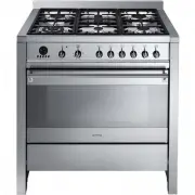
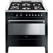
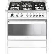
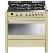
Description 11 EN 2 Description 2.1 General Description 1 Backguard 2 Cooking hob 3 Control panel 4 Oven light 5 Seal 6 Door 7 Fan 8 Storage compartment Rack/tray support frame shelf
Page 10 - Door lock indicator light
Description 12 2.2 Cooking hob AUX = AuxiliarySR = Semi-rapid R = RapidDUAL = Ultra rapid 2.3 Control panel 1 Door lock indicator light It comes on when the automatic cleaning cycle (Pyrolytic) is activated. 2 Function knob The oven's various functions are suitable for different cooking modes. After...
Page 11 - Programmer clock; Available accessories; Rack
Description 13 EN 6 Programmer clock Useful for displaying the current time, setting programmed cooking operations and programming the minute minder timer. 2.4 Other parts Shelves The appliance features shelves for positioning trays and racks at different heights. The insertion heights are indicated...
Page 12 - Tray rack
Description 14 Tray rack To be placed over the top of the oven tray; for cooking foods which may drip. Deep tray Useful for collecting fat from foods placed on the rack above. Rotisserie rod Useful for cooking chicken and all foods which require uniform cooking over their entire surface. Reduction p...
Page 13 - Use; Danger of burns
Use 15 EN 3 Use 3.1 Instructions High temperature inside the oven during use Danger of burns • Keep the oven door closed during cooking. • Protect your hands wearing heat resistant gloves when moving food inside the oven. • Do not touch the heating elements inside the oven. • Do not pour water direc...
Page 14 - Escaping gas may cause an explosion.
Use 16 Escaping gas may cause an explosion. If you smell gas or notice any faults in the gas installation:• Immediately shut off the gas supply or close the gas cylinder valve. • Immediately extinguish all naked flames and cigarettes. • Do not use any light or appliance switches and do not pull any ...
Page 15 - Using the accessories; Reduction pan stands
Use 17 EN 3.3 Using the accessories Reduction pan stands The reduction pan stands have to be placed on the hob grids. Make sure they are properly placed. Tray rack The tray rack has to be inserted into the tray. In this way fat can be collected separately from the food which is being cooked. Racks a...
Page 16 - Rotisserie rod
Use 18 Rotisserie rod 1. Insert the 4 supplied bushings in the 4 corner holes of the deep tray and screw them onto the ring nuts with a suitable tool (such as a screwdriver). 2. Position the rotisserie supports in the bushings as shown in the figure below. 3. Prepare the rotisserie rod with the food...
Page 17 - Using the storage compartment
Use 19 EN 6. Insert the tip of the rod in the rotisserie motor housing on the left of the rear wall of the oven. 7. To activate the rotisserie, turn the function knob to the position and set the cooking temperature using the temperature knob. 8. When cooking is complete, remove the tray with the rot...
Page 18 - Using the cooktop; Practical tips for using the hob
Use 20 3.5 Using the cooktop All the appliance's control and monitoring devices are located together on the front panel. The burner controlled by each knob is shown next to the knob. The appliance is equipped with an electronic ignition device. Simply press the knob and turn it anti-clockwise to the...
Page 19 - Switching on the oven
Use 21 EN 3.6 Using the oven Switching on the oven To switch on the oven:1. Select the cooking function using the function knob. 2. Select the temperature using the temperature knob. Functions list Ensure that the programmer clock shows the cooking duration symbol , otherwise it will not be possible...
Page 20 - Fan assisted; and
Use 22 Fan assisted The operation of the fan, combined with traditional cooking, ensures consistent cooking even with complex recipes. Perfect for biscuits and cakes, even when simultaneously cooked on several levels. (For multiple-level cooking, we recommend using the 2 nd and 4 th shelf). Fan forc...
Page 21 - General advice
Use 23 EN 3.7 Cooking advice General advice • Use a fan assisted function to achieve consistent cooking at several levels. • It is not possible to shorten cooking times by increasing the temperature (the food could be overcooked on the outside and undercooked on the inside). Advice for cooking meat ...
Page 22 - To save energy
Use 24 To save energy • Stop cooking a few minutes before the time normally used. Cooking will continue for the remaining minutes with the heat which has accumulated inside the oven. • Reduce any opening of the door to a minimum to avoid heat dispersal. • Keep the inside of the appliance clean at al...
Page 23 - Timed cooking
Use 25 EN Timed cooking 1. After selecting a cooking function and temperature, press the key . The display will show the digits and the symbol displayed between the hours and the minutes. 2. Use the key or to set the required minutes. 3. Wait approx. 5 seconds without pressing any key in order for t...
Page 24 - Minute minder timer
Use 26 5. At the end of cooking the heating elements will be deactivated. On the display, the symbol turns off, the symbol flashes and the buzzer sounds. 6. To turn off the buzzer just press any key of the programmer clock. 7. Press the keys and at the same time to reset the programmer clock. Minute...
Page 25 - Cooking information table
Use 27 EN Cooking information table Food Weight (Kg) Function Shelf Temperature (°C) Time (minutes) Lasagne 3 - 4 Convection 1 220 - 230 45 - 50 Pasta bake 3 - 4 Convection 1 220 - 230 45 - 50 Roast veal 2 Fan assisted/Fan forced 2 180 - 190 90 - 100 Pork 2 Fan assisted/Fan forced 2 180 - 190 70 - 8...
Page 26 - Cleaning and maintenance; Cleaning the appliance; Recommendations for cleaning the hob
Cleaning and maintenance 28 4 Cleaning and maintenance 4.1 Instructions 4.2 Cleaning the appliance Recommendations for cleaning the hob To keep the surfaces in good condition, they should be cleaned regularly after use. Let them cool first. Cleaning the hob 1. Pour some non-abrasive detergent on a d...
Page 27 - Cleaning the igniters and thermocouples
Cleaning and maintenance 29 EN Cleaning the igniters and thermocouples • If necessary, clean the igniters and thermocouples with a damp cloth. • If there is any dry residue, remove it with a toothpick or needle. Cleaning the oven cavity In order to keep your oven in the best possible condition, clea...
Page 28 - Door lock lever activated; Move the door lock lever to the right until
Cleaning and maintenance 30 Manually disengaging the door lock lever The door lock lever is located in the first slot on the left under the control panel, in the upper part of the front of the oven. During normal cleaning operations, the door lock lever may be activated accidentally. Door lock lever...
Page 29 - Preliminary operations
Cleaning and maintenance 31 EN 4.3 Pyrolytic cycle Preliminary operations Before starting the pyrolytic cycle:• Clean the internal glass panel following the usual cleaning instructions. • For very stubborn encrustations spray an oven cleaning product onto the glass (read the warnings on the product)...
Page 30 - At the end of the pyrolytic cycle, the door; Removing the door; Grasp the door on both sides with both
Cleaning and maintenance 32 7. At the end of the pyrolytic cycle, the door remains locked as long as the temperature inside the oven returns to safety levels. 8. At the end of the pyrolytic cycle, wait for the oven to cool down and collect the residues deposited inside with a damp microfibre cloth. ...
Page 31 - Cleaning the door glazing; Removing the internal glass panes
Cleaning and maintenance 33 EN 3. To reassemble the door, put the hinges in the relevant slots in the oven, making sure that grooved sections A are resting completely in the slots. Lower the door and once it is in place remove the pins from the holes in the hinges. 4.5 Cleaning the door glazing The ...
Page 32 - Remove the intermediate glass pane by; Extraordinary maintenance; Replacing the oven light bulb
Cleaning and maintenance 34 5. Remove the intermediate glass pane by lifting it upwards. 6. Clean the external glass pane and the panes removed previously. Use absorbent kitchen roll. In case of stubborn dirt, wash with a damp sponge and neutral detergent. 7. When you have finished cleaning, reinser...
Page 33 - The appliance does not work.
Cleaning and maintenance 35 EN 4. Slide out and remove the light bulb. 5. Fit the new light bulb. 6. Refit the cover. Ensure the moulded part of the glass (A) is facing the door. 7. Press the cover completely down so that it attaches perfectly to the bulb support. What to do if... The appliance does...
Page 34 - Installation; Minimum clearance to combustible surfaces; Freestanding cooker
Installation 36 5 Installation 5.1 Minimum clearance to combustible surfaces Freestanding cooker A 600 mm (Overhead) measured from the highest part of the highest burner and 750 mm for an exhaust fan. B 200 mm (Vertical combustible surface) measured form the edge of the nearest burner. C 10 mm (Hori...
Page 35 - Natural Gas; Gas Approval Consulting Pty Ltd Smeg
Installation 37 EN This appliance is suitable for connection with rigid pipe or flexible hose. The isolating manual shut-off valve connection point must be accessible when the appliance is installed.Flexible hose assembly must be certified to AS/NZS 1869 class B or D, be of appropriate internal diam...
Page 36 - Room ventilation; Adaptation to different types of; Replacing nozzles
Installation 38 Room ventilation The room containing the appliance should have a permanent air supply in accordance with the standards in force. The room where the appliance is installed must have enough air flow needed for the regular combustion of gas and the necessary air change in the room itsel...
Page 37 - Replace the burners in the correct
Installation 39 EN 3. Replace the burners in the correct position. Adjusting the minimum setting for natural or city gas Light the burner and turn it to the minimum position. Extract the gas tap knob and turn the adjustment screw next to the tap rod (depending on the model) until the correct minimum...
Page 38 - Burner and nozzle characteristics table; Heavy appliance
Installation 40 Burner and nozzle characteristics table 5.4 Positioning Appliance dimensions (mm) Location of gas and electrical connection points. NG 1.0 kPA AUX SR R DUAL (int + ext) Nominal gas consumption (MJ/h) 3.9 7.5 12 17.0 Injector (1/100 mm) 90 120 155 81 + 170 ULPG 2.75 kPa AUX SR R DUAL ...
Page 39 - Positioning and levelling
Installation 41 EN Positioning and levelling Properly level the appliance on the floor to ensure better stability.• After making the electrical and/or gas connections, screw or unscrew the bottom part of the foot until the appliance is stable and level on the floor. Assembling the skirt The backguar...
Page 40 - Wall fixing
Installation 42 1. Open the storage compartment. 2. Place the toe skirt in the front bottom part of the appliance. 3. Screw the four side screws to fasten the toe skirt to the appliance. 4. Cover the holes of the toe skirt with the plugs provided. Wall fixing 1. Turn the screw placed behind the cook...
Page 41 - Drill the hole and insert a wall plug.; Electrical connection; General information
Installation 43 EN 5. Drill the hole and insert a wall plug. 6. Attach the chain and push the appliance to the wall. 5.5 Electrical connection General information Check the grid characteristics against the data indicated on the plate.The identification plate bearing the technical data, serial number...
Page 42 - Fixed connection
Installation 44 The appliance can work in the following modes:• 220-240 V 2 ~ 3 x 2.5 mm² three-pole cable. • 220-240 V 3 ~ 4 x 2.5 mm² four-pole cable. • 220-240 V 1N ~ 3 x 2.5 mm² three-pole cable. • 380-415 V 2N ~ 4 x 2.5 mm² four-pole cable. • 380-415 V 3N ~ 5 x 1.5 mm² five-pole cable. Fixed co...
Page 43 - For the installer
Installation 45 EN 3. Proceed with installation of the power supply cable. 4. When you have finished, reposition the plate on the rear casing and fasten it in place with the previously removed screws. 5.6 For the installer • The plug must remain accessible after the installation is complete. Do not ...


 Smeg A1C-6
User Manual
Smeg A1C-6
User Manual
 Smeg A1C-7
User Manual
Smeg A1C-7
User Manual
 Smeg A2-8
User Manual
Smeg A2-8
User Manual
 Smeg A2BL-8
User Manual
Smeg A2BL-8
User Manual
 Smeg A5-8
User Manual
Smeg A5-8
User Manual
 Smeg B901GMXI9
User Manual
Smeg B901GMXI9
User Manual
 Smeg C95GMCA9-1
User Manual
Smeg C95GMCA9-1
User Manual
 Smeg CPF30UGGWH
User Manual
Smeg CPF30UGGWH
User Manual
 Smeg CPF36UGGWH
User Manual
Smeg CPF36UGGWH
User Manual
 Smeg CPF36UGMAN
User Manual
Smeg CPF36UGMAN
User Manual
 Smeg CPF48UGMBL
User Manual
Smeg CPF48UGMBL
User Manual
 Smeg CS19-7
User Manual
Smeg CS19-7
User Manual
 Smeg CS19A-7
User Manual
Smeg CS19A-7
User Manual
 Smeg CS19B-6
User Manual
Smeg CS19B-6
User Manual
 Smeg CS19P-6
User Manual
Smeg CS19P-6
User Manual
 Smeg CS19P-9
User Manual
Smeg CS19P-9
User Manual
 Smeg CS19RW-6
User Manual
Smeg CS19RW-6
User Manual
 Smeg CS19RW-7
User Manual
Smeg CS19RW-7
User Manual
 Smeg CX60ISVT9
User Manual
Smeg CX60ISVT9
User Manual