Smeg PGA31G-1 - Manuals
User Manual Smeg PGA31G-1


Summary
Instructions 4 1 Instructions 1.1 General safety instructions Risk of personal injury • WARNING: The appliance and its accessible parts become hot during use. • Never try to put out a fire or flames with water: turn off the appliance and smother the flames with a fire blanket or other appropriate co...
Instructions 5 EN • Do not use aerosols in the vicinity of this appliance whilst it is in use. • Switch off the appliance after use.• Do not modify this appliance.• Do not try to repair the appliance yourself or without the intervention of a qualified technician. • Do not pull the cable to remove th...
Instructions 7 EN • This domestic appliance is not connected to a device for extracting combustion products. It must be installed and connected in accordance with current installation regulations. Pay particular attention to the relevant requirements regarding ventilation. For this appliance • Do no...
Smeg Hobs Manuals
-
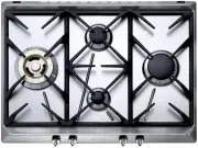
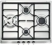
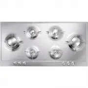
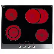
 Smeg CIR574X3
User Manual
Smeg CIR574X3
User Manual
-
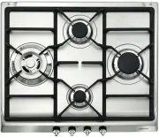
 Smeg CIR574XS3
User Manual
Smeg CIR574XS3
User Manual
-
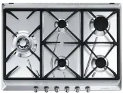 Smeg CIR575X
User Manual
Smeg CIR575X
User Manual
-
Smeg CIR575X
Manual
-
 Smeg CIR597XS
User Manual
Smeg CIR597XS
User Manual
-
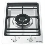
 Smeg CIR60X
User Manual
Smeg CIR60X
User Manual
-
Smeg CIR60X
Manual
-
 Smeg CIR60XS3
User Manual
Smeg CIR60XS3
User Manual
-
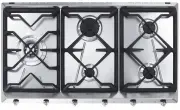
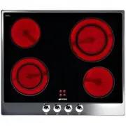
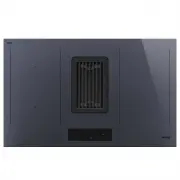 Smeg HOBD182DG
User Manual
Smeg HOBD182DG
User Manual
-
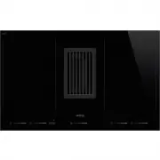 Smeg HOBD682D1
User Manual
Smeg HOBD682D1
User Manual
-
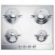
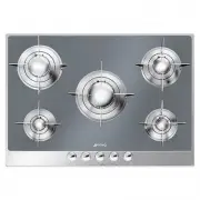
 Smeg P106
User Manual
Smeg P106
User Manual
-
Smeg P106
Manual
-
 Smeg P1641XA
User Manual
Smeg P1641XA
User Manual
-
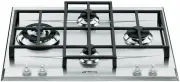
 Smeg P64
User Manual
Smeg P64
User Manual
-
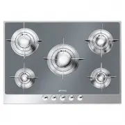
 Smeg P652
User Manual
Smeg P652
User Manual
-
Smeg P652
Manual
-
 Smeg P663-1
User Manual
Smeg P663-1
User Manual
-
 Smeg P705ES
User Manual
Smeg P705ES
User Manual
-
 Smeg P705VT
User Manual
Smeg P705VT
User Manual
-
Smeg P705VT
Manual