Smeg OTR316XU - Manuals
Smeg OTR316XU Microwave – User Manual in PDF format online.
Manuals:
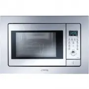
User Manual Smeg OTR316XU


Summary
2 Before You Use Your Microwave CONTENTS General information Important Safety Instructions .................................. 3 Electrical Requirements .......................................... 3 Damage – Shipment/Installation.............................. 4 Parts Included.............................
PART QUANTITY Wood Screws 2 ( 1 ⁄ 4 “ x 2“) Toggle Bolts (andwing nuts) ( 3 ⁄ 16 “ x 3“) Self-Aligning Machine 3 Screws ( 1 ⁄ 4 “ x 3 1 ⁄ 4 “) Nylon Grommet(for metal cabinets) 1 • If the unit is damaged in shipment, return the unit to the store in which it was bought for repairor replacement. • If ...
TOOLS YOU WILL NEED # 1 Phillips screwdriver Pencil Ruler or tape measure andstraight edge Carpenter square(optional) Tin snips (for cuttingdamper, if required) Electric drill with 3 ⁄ 16 “ , 1 ⁄ 2 “ and 5 ⁄ 8 “ drill bits Hammer (optional) Stud finder or Filler blocks or scrapwood pieces, if needed...
Smeg Microwaves Manuals
-
 Smeg FME20EX3
User Manual
Smeg FME20EX3
User Manual
-
 Smeg FME20TC3
User Manual
Smeg FME20TC3
User Manual
-
 Smeg FME24B-2
User Manual
Smeg FME24B-2
User Manual
-
 Smeg FME24N-2
User Manual
Smeg FME24N-2
User Manual
-
 Smeg FME24X-2
User Manual
Smeg FME24X-2
User Manual
-
 Smeg FMI120
User Manual
Smeg FMI120
User Manual
-
 Smeg FMI325X
User Manual
Smeg FMI325X
User Manual
-
 Smeg FMIU020X
User Manual
Smeg FMIU020X
User Manual
-
 Smeg SA34MX
User Manual
Smeg SA34MX
User Manual
-
 Smeg SA35MX
User Manual
Smeg SA35MX
User Manual
-
Smeg SA35MX
Manual
-
 Smeg SA37X
User Manual
Smeg SA37X
User Manual
-
Smeg SA37X
Manual
-
 Smeg SA384X
User Manual
Smeg SA384X
User Manual
-
Smeg SA384X
Manual
-
 Smeg SA45MX2
User Manual
Smeg SA45MX2
User Manual
-
 Smeg SA985-2CX
User Manual
Smeg SA985-2CX
User Manual
-
Smeg SA985-2CX
Manual
-
 Smeg SA985-2CX1
User Manual
Smeg SA985-2CX1
User Manual
-
 Smeg SA987CX
User Manual
Smeg SA987CX
User Manual