Page 2 - Instructions; General safety instructions; Risk of personal injury
Instructions 4 1 Instructions 1.1 General safety instructions Risk of personal injury • During use the appliance and its accessible parts become very hot. • Never touch the heating elements during use. • Keep children under eight years of age at a safe distance if they are not constantly supervised....
Page 3 - Risk of damaging the appliance; Identification plate; • The identification plate bears the; Manufacturer liability; • non-observance of the user manual
Instructions 5 EN Risk of damaging the appliance • Do not use abrasive or corrosive detergents on glass parts (e.g. powder products, stain removers and metallic sponges). • Racks and trays have to be inserted into the side guides until they come to a complete stop. The mechanical safety locks that p...
Page 4 - Appliance purpose; • This appliance is intended for cooking; How to read the user manual
Instructions 6 1.4 Appliance purpose • This appliance is intended for cooking food in the home environment. Every other use is considered improper. • The appliance is not designed to operate with external timers or with remote-control systems. 1.5 This user manual This user manual is an integral par...
Page 5 - Description; General Description
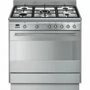
Description 7 EN 2 Description 2.1 General Description 1 Backguard 2 Cooktop 3 Control panel 4 Oven light 5 Seal 6 Door 7 Fan 8 Storage compartment Rack/tray support frame shelf
Page 6 - Cooktop burner knobs
Description 8 2.2 Cooktop AUX = AuxiliarySR = Semi-rapid R = RapidUR2 = Ultra rapid 2.3 Control panel 1 Cooktop burner knobs Useful for lighting and adjusting the cooktop burners.Press and turn the knobs anti-clockwise to the value to light the relative burners. Turn the knobs to the zone between th...
Page 8 - Available accessories; Ring reducer
Description 10 2.5 Available accessories Ring reducer Useful when using small cookware. WOK ring Useful when using a wok. Teppanyaki plate (on some models only) Useful for cooking meat, fish and vegetables directly on the plate without adding fats or oils, staying true to the tradition of Japanese c...
Page 9 - Tray
Description 11 EN Tray Useful for collecting fat from foods placed on the rack above. Deep tray Useful for collecting fat from foods placed on the rack above. Rotisserie rod (on some models only) Useful for cooking chicken and all foods which require uniform cooking over their entire surface. Rack U...
Page 10 - Use; Danger of burns
Use 12 3 Use 3.1 Instructions High temperature inside the oven during use Danger of burns • Keep the oven door closed during cooking. • Protect your hands wearing heat resistant gloves when moving food inside the oven. • Do not touch the heating elements inside the oven. • Do not pour water directly...
Page 11 - Escaping gas may cause an explosion.
Use 13 EN Escaping gas may cause an explosion. If you smell gas or notice any faults in the gas installation:• Immediately shut off the gas supply or close the gas cylinder valve. • Immediately extinguish all naked flames and cigarettes. • Do not use any light or appliance switches and do not pull a...
Page 12 - Using the accessories; Ring reducers
Use 14 3.3 Using the accessories Ring reducers The ring reducers have to be placed on the cooktop grids. Make sure they are placed properly. Using the Teppanyaki plate (on some models only) • The burners under the plate can be lit at the same time to the maximum setting for no more than 10 minutes ....
Page 13 - Racks and trays
Use 15 EN Racks and trays Racks and trays have to be inserted into the side guides until they come to a complete stop.• The mechanical safety locks that prevent the rack from being taken out accidentally have to face downwards and towards the oven back. Rotisserie rod (on some models only) 1. Insert...
Page 14 - Prepare the rotisserie rod with the food
Use 16 3. Prepare the rotisserie rod with the food using the clip forks provided. The clip forks can be tightened using the fastening screws. 4. Once you have prepared the rotisserie rod, place it on the supports. Insert the tip of the rod in the housing of the mechanism on the left-hand support unt...
Page 15 - Using the cooktop
Use 17 EN 7. To activate the rotisserie, turn the function knob to the position and set the cooking temperature using the temperature knob. 8. When cooking is complete, remove the tray with the rotisserie. 9. Screw on the handle provided so that you can handle the rotisserie rod more easily. 3.4 Usi...
Page 16 - Practical tips for using the cooktop; Using the storage compartment; Switching on the oven
Use 18 Correct positioning of the flame-spreader crowns and burner caps Before lighting the cooktop burners, make sure that the flame-spreader crowns are correctly positioned in their housings with their respective burner caps. Make sure that the holes 1 in the flame-spreader crowns are aligned with...
Page 17 - Preheating stage
Use 19 EN Preheating stage Cooking functions are always preceded by a preheating stage, which allows the appliance to heat up to cooking temperature.The indicator light comes on to indicate that the oven is heating up.The indicator light turns off to indicate that the food can be placed inside the o...
Page 18 - General advice; Fan forced
Use 20 3.7 Cooking advice General advice • Use a fan assisted function to achieve consistent cooking at several levels. • It is not possible to shorten cooking times by increasing the temperature (the food could be overcooked on the outside and undercooked on the inside). Advice for cooking meat • C...
Page 19 - Advice for defrosting and proving
Use 21 EN Advice for cooking desserts/pastries and biscuits • Use dark metal moulds: they help to absorb the heat better. • The temperature and the cooking time depend on the quality and consistency of the dough. • To check whether the dessert is cooked right through: at the end of the cooking time,...
Page 20 - Setting the time
Use 22 Setting the time On the first use, or after a power failure, the digits will be flashing on the appliance’s display. 1. Hold down the clock key for two seconds. The dot between the hours and the minutes flashes. 2. The time can be set via the value increase key and value decrease key . Keep t...
Page 21 - Programmed cooking
Use 23 EN 6. Press the clock key to reset the programmer clock. Programmed cooking 1. Set the cooking time as described in the previous point “Timed cooking”. 2. Hold the menu key down for 2 seconds. 3. Press the menu key again. The display will show the digits and the text in sequence, while the sy...
Page 22 - Minute minder timer
Use 24 Minute minder timer The minute minder timer can be activated at any time. 1. Keep the clock key pressed for per a few seconds. The display shows the figures and the symbol flashing between the hours and minutes. 2. Use the value increase and value decrease keys to set the number of minutes re...
Page 23 - Cooking information table
Use 25 EN Cooking information table Food Weight (Kg) Function Runner posi-tion from the bottom Temperature (°C) Time (minutes) Lasagne 3 - 4 Convection 1 220 - 230 45 - 50 Pasta bake 3 - 4 Convection 1 220 - 230 45 - 50 Roast veal 2 Fan assisted/Fan forced 2 180 - 190 90 - 100 Pork 2 Fan assisted/Fa...
Page 24 - Cleaning and maintenance; Cleaning the appliance; Cleaning the cooktop
Cleaning and maintenance 26 4 Cleaning and maintenance 4.1 Instructions 4.2 Cleaning the appliance Recommendations for cleaning the cooktop To keep the surfaces in good condition, they should be cleaned regularly after use. Let them cool first. Cleaning the cooktop 1. Pour some non-abrasive detergen...
Page 25 - Cleaning the igniters and thermocouples
Cleaning and maintenance 27 EN Teppanyaki plate (on some models only) The Teppanyaki plate is easier to clean when it is still lukewarm.Use conventional specific detergents for stainless steel and non-abrasive sponges. Any remaining encrustations or food residues can be easily removed by soaking the...
Page 26 - Removing the door; Grasp the door on both sides with both; Cleaning the door glazing
Cleaning and maintenance 28 4.3 Removing the door For easier cleaning, the door can be removed and placed on a tea towel.To remove the door proceed as follows:1. Open the door completely and insert two pins into the holes on the hinges indicated in the figure. 2. Grasp the door on both sides with bo...
Page 27 - Removing the internal glass panes; Some models have an intermediate glass
Cleaning and maintenance 29 EN 4.5 Removing the internal glass panes For easier cleaning the door internal glass panes can be disassembled.1. Remove the internal glass pane by pulling the rear part gently upwards, following the movement indicated by the arrows ( 1 ). 2. Then, pull the front part upw...
Page 28 - Removing racks/trays support frames
Cleaning and maintenance 30 Removing racks/trays support frames Removing the guide frames enables the sides to be cleaned more easily. This operation should be performed each time the automatic cleaning cycle is used (on some models only).To remove the guide frames: Pull the frame towards the inside...
Page 29 - Vapour Clean setting
Cleaning and maintenance 31 EN • Pour approximately 40 cc of water into the tray. Make sure it does not overflow out of the cavity. • Spray a water and washing up liquid solution inside the oven using a spray nozzle. Direct the spray against the side walls, upwards, downwards and towards the deflect...
Page 30 - Extraordinary maintenance; Removing and installing the oven seal
Cleaning and maintenance 32 4.7 Extraordinary maintenance Removing and installing the oven seal To remove the oven seal:• Unhook the clips in the 4 corners and in the centre, then pull the oven seal. To install the oven seal:• Hook the clips in the 4 corners and in the centre onto the oven seal. Ove...
Page 31 - The appliance does not work.
Cleaning and maintenance 33 EN 4. Slide out and remove the light bulb. 5. Fit the new light bulb. 6. Refit the cover. Ensure the moulded part of the glass (A) is facing the door. 7. Press the cover completely down so that it attaches perfectly to the bulb support. What to do if... The appliance does...
Page 32 - Installation; Clearances above and around domestic appliances; Requirements
Installation 34 5 Installation 5.1 Clearances above and around domestic appliances This appliance must be installed by an authorised person in accordance with this instruction manual, AS/NZS 5601.1 – Gas installations (installation and pipe sizing), local gas fitting regulations, local electrical re...
Page 33 - Additional requirements for
Installation 35 EN 3. Additional requirements for Freestanding and Elevated Cooking Appliaces – (Measurements D & E) Where D, the distance from the periphery of the nearest burner to a horizontal combustible surface is less than 200 mm, then E shall be 10 mm or more, or the horizontal surface sh...
Page 34 - The regulator supplied must be fitted
Installation 36 Connection of the appliance to the gas supply must be in accordance with the requirements of AS5601. A ½” BSP connector at the inlet is recommended and the gas supply line to the appliance must be of adequate length to allow sufficient withdrawal of appliance for service or disconnec...
Page 35 - Connection to liquid gas
Installation 37 EN Connection to liquid gas Use a pressure regulator and make the connection on the gas cylinder following the guidelines set out in the regulations in force.Make sure that the supply pressure complies with the values indicated in section “ Burner and nozzle characteristics table”. R...
Page 36 - Adaptation to different types of; Replacing nozzles
Installation 38 5.3 Adaptation to different types of gas In case of operation with other types of gas, the burner nozzles must be changed and the minimum flame adjusted on the gas cocks. Replacing nozzles 1. Remove the pan stands, burner caps and flame-spreader crowns to access the burner casings. 2...
Page 37 - Burner and nozzle characteristics table; Heavy appliance
Installation 39 EN Burner and nozzle characteristics table Overall dimensions Location of gas and electrical connection points. 5.4 Positioning 1 ULPG 2.75 kPa AUX SR R UR2 Nominal gas consumption (MJ/h) 3.9 6.3 10.8 15.2 Injector (1/100 mm) 54 68 88 46 + 94 2 NG 1.0 kPA AUX SR R UR2 Nominal gas con...
Page 38 - General information
Installation 40 General information This appliance may be installed next to walls, one of which must be higher than the worktop, at a minimum distance of 50 mm from the side of the appliance, as shown in figures A and C relative to the installation classes.Any wall units positioned above the worktop...
Page 39 - Positioning and levelling
Installation 41 EN Positioning and levelling • After making the gas and electrical connections, screw on the four feet supplied with the appliance. The appliance must sit level on the floor to ensure stability.• Screw or unscrew the bottom part of the foot until the appliance is stable and level on ...
Page 40 - Fastening to the wall
Installation 42 Fastening to the wall 1. Screw the wall fastening plate to the rear of the appliance. 2. Adjust the height of the 4 feet. 3. Assemble the fastening bracket. 4. Align the base of the hook on the fastening bracket with the base of the slot on the wall fastening plate. The anti-tip devi...
Page 42 - Wall fixing
Installation 44 Wall fixing 1. Turn the screw placed behind the cooktop near the gas connection. 2. Attach the chain to the cooker with the screw just removed. 3. Stretch it out horizontally so that the other end of the chain touches the wall. 4. Mark the wall in the position where the hole is to be...
Page 43 - Electrical connection
Installation 45 EN 5.5 Electrical connection General information Check the grid characteristics against the data indicated on the plate.The identification plate bearing the technical data, serial number and brand name is visibly positioned on the appliance.Do not remove this plate for any reason.Per...
Page 44 - For the installer
Installation 46 5.6 For the installer • The plug must remain accessible after the installation is complete. Do not kink or trap the mains connection cable. • The appliance must be fitted according to the installation diagrams. • Do not attempt to turn or stress the threaded elbow on the manifold. Yo...
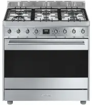


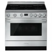
 Smeg A1PYID-9
User Manual
Smeg A1PYID-9
User Manual
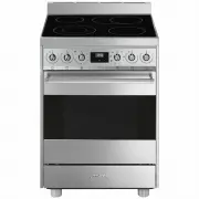
 Smeg ALFA625EHDS
User Manual
Smeg ALFA625EHDS
User Manual
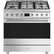
 Smeg C6GMXA8
User Manual
Smeg C6GMXA8
User Manual
 Smeg C9GMX
User Manual
Smeg C9GMX
User Manual
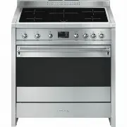
 Smeg C9IMX2
User Manual
Smeg C9IMX2
User Manual
 Smeg C9IMX9-1
User Manual
Smeg C9IMX9-1
User Manual
 Smeg CPF9IPAN
User Manual
Smeg CPF9IPAN
User Manual
 Smeg CPF9IPBL
User Manual
Smeg CPF9IPBL
User Manual
 Smeg CPF9IPOG
User Manual
Smeg CPF9IPOG
User Manual
 Smeg CPF9IPOR
User Manual
Smeg CPF9IPOR
User Manual
 Smeg CPF9IPWH
User Manual
Smeg CPF9IPWH
User Manual
 Smeg CPF9IPX
User Manual
Smeg CPF9IPX
User Manual
 Smeg CS6CMXA
User Manual
Smeg CS6CMXA
User Manual
 Smeg CS9GMXA2
User Manual
Smeg CS9GMXA2
User Manual
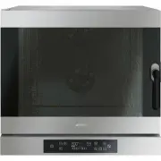
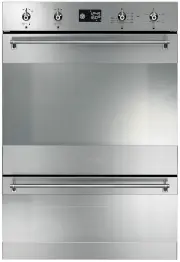 Smeg DOSPA38X
User Manual
Smeg DOSPA38X
User Manual
 Smeg DOSPA6395X
User Manual
Smeg DOSPA6395X
User Manual
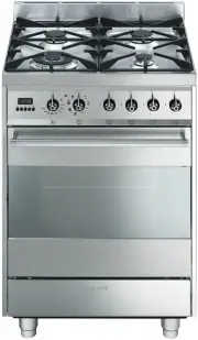
 Smeg FS61XNG8
User Manual
Smeg FS61XNG8
User Manual
 Smeg FS9010CER-1
User Manual
Smeg FS9010CER-1
User Manual
 Smeg FS9606XS
User Manual
Smeg FS9606XS
User Manual
 Smeg FS9606XS1
User Manual
Smeg FS9606XS1
User Manual