Siemens ET 77E Series - Manuals
Siemens ET 77E Series – User Manual in PDF format online.
Manuals:
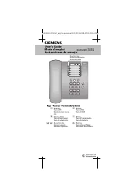
User Manual Siemens ET 77E Series


Summary
SD77 TABLE OF CONTENTS SECTION AND TITLE PAGE 1.0 INTRODUCTION .................................................................................................................................................6 1.1 MODEL DESIGNATION .......................................................................
SD77 LIST OF ILLUSTRATIONS FIGURE AND TITLE PAGE 1-1 Sample Rating Labels.............................................................................................................................................7 2-1 Transducer Installation and Mounting Dimensions ...................................
SD77 PREFACE Conventions and Symbols The following symbols may be used in this manual and may appear on the equipment. The reader should be familiar with the symbols and their meanings. Symbols are provided to quickly alert the reader to safety related text. Symbol Meaning DANGER Indicates an immedi...
Siemens Manuals
-
 Siemens 140
User Manual
Siemens 140
User Manual
-
 Siemens 2000
User Manual
Siemens 2000
User Manual
-
 Siemens 2010
User Manual
Siemens 2010
User Manual
-
 Siemens 2015
User Manual
Siemens 2015
User Manual
-
 Siemens 300
User Manual
Siemens 300
User Manual
-
 Siemens 3000
User Manual
Siemens 3000
User Manual
-
 Siemens 4000
User Manual
Siemens 4000
User Manual
-
 Siemens 440
User Manual
Siemens 440
User Manual
-
 Siemens 54
User Manual
Siemens 54
User Manual
-
 Siemens 6RA70
User Manual
Siemens 6RA70
User Manual
-
 Siemens 8WD44
User Manual
Siemens 8WD44
User Manual
-
 Siemens A110
User Manual
Siemens A110
User Manual
-
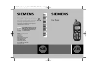 Siemens A35
User Manual
Siemens A35
User Manual
-
 Siemens A36
User Manual
Siemens A36
User Manual
-
 Siemens A40
User Manual
Siemens A40
User Manual
-
 Siemens A51
User Manual
Siemens A51
User Manual
-
 Siemens A52
User Manual
Siemens A52
User Manual
-
 Siemens A55
User Manual
Siemens A55
User Manual
-
 Siemens A56
User Manual
Siemens A56
User Manual
-
 Siemens A60
User Manual
Siemens A60
User Manual