Samsung MIM-F10N - Manuals
User Manual Samsung MIM-F10N


Summary
2 PREP ARA TION This installation manual explains how to install a FCU interface module that is connected to a Samsung FCU KIT. Please read this manual thoroughly before installing the product. (Please refer to appropriate installation for any optional product installation.) WARNING Hazards or unsaf...
3 PREP ARA TION Do not install the product in a place where flammable gas leaks or if there is possible chance of leakage. • Ɵ˵ʪθʪ̈ϑθ̈ϑ̧ͱ˙ѣθʪͱθʪуΧ̷ͱϑ̈ͱ͝ Do not install the product in a place where it will be exposed to oil or vapor etc. • If the product is used in a place where it is exposed to oil...
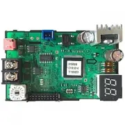
4 INST ALLA TION FCU interface module installation Accessories Item FCU interface module DC power cable (12 V) Communication cable Case Cable tie Screw (M4) Installation Manual Shape Diagram of connection between a FCU interface module and FCU KIT 1 Fix the FCU interface module case at fixing point ...
Samsung Air Conditioners Manuals
-
 Samsung AM022TNVDKH/TK
User Manual
Samsung AM022TNVDKH/TK
User Manual
-
 Samsung AQ07S8GE
User Manual
Samsung AQ07S8GE
User Manual
-
Samsung AQ07S8GE
Manual
-
 Samsung AQ09FAX
User Manual
Samsung AQ09FAX
User Manual
-
 Samsung AQ09JWAX
User Manual
Samsung AQ09JWAX
User Manual
-
 Samsung AQ12FAN
User Manual
Samsung AQ12FAN
User Manual
-
 Samsung AQ12JWAN
User Manual
Samsung AQ12JWAN
User Manual
-
 Samsung AQ18FENSER
User Manual
Samsung AQ18FENSER
User Manual
-
 Samsung AR09TXHYBWKN/AR09TXHYBWKX
User Manual
Samsung AR09TXHYBWKN/AR09TXHYBWKX
User Manual
-
 Samsung AVMGH052EA4
User Manual
Samsung AVMGH052EA4
User Manual
-
 Samsung AVMKH026EA4
User Manual
Samsung AVMKH026EA4
User Manual
-
 Samsung AW05B0LA/AW0519
User Manual
Samsung AW05B0LA/AW0519
User Manual
-
 Samsung AW07A0SE/AW07A1SE
User Manual
Samsung AW07A0SE/AW07A1SE
User Manual
-
 Samsung AW126JB/127JB
User Manual
Samsung AW126JB/127JB
User Manual
-
 Samsung AW-1407B
User Manual
Samsung AW-1407B
User Manual
-
 Samsung AWH126JE
User Manual
Samsung AWH126JE
User Manual
-
 Samsung F-AR09BXGYCWK1
User Manual
Samsung F-AR09BXGYCWK1
User Manual
-
 Samsung F-AR09FSSSCWK1
User Manual
Samsung F-AR09FSSSCWK1
User Manual
-
 Samsung F-AR12BXGYCWK1
User Manual
Samsung F-AR12BXGYCWK1
User Manual
-
 Samsung F-AR12FSSSCWK1
User Manual
Samsung F-AR12FSSSCWK1
User Manual