Page 2 - GENERAL SAFETY RULES; Save all warnings and instructions for future reference.; WORK AREA SAFETY; Keep work area clean and well lit.; ELECTRICAL SAFETY; Do not expose power tools to rain or wet conditions.; PERSONAL SAFETY
2 − English GENERAL SAFETY RULES WARNING: Read all safety warnings, instructions, illustrations and specifications provided with this power tool. Failure to follow all instructions listed below may result in electric shock, fire and/or serious injury. Save all warnings and instructions for future re...
Page 3 - the workpiece into the blade or cut ”freehand” in any; Cut only one workpiece at a time.; SERVICE
3 − English GENERAL SAFETY RULES MITER SAW SPECIFIC SAFETY RULES Miter saws are intended to cut wood or wood-like products, they cannot be used with abrasive cut-off wheels for cutting ferrous material such as bars, rods, studs, etc. Abrasive dust causes moving parts such as the lower guard to jam...
Page 4 - MITER SAW SPECIFIC SAFETY RULES; Use the proper extension cord.; ADDITIONAL SAFETY RULES; Inspect extension cords periodically
4 − English MITER SAW SPECIFIC SAFETY RULES Plan your work. Every time you change the bevel or miter angle setting, make sure the adjustable fence is set correctly to support the workpiece and will not interfere with the blade or the guarding system. Without turning the tool ”ON” and with no work...
Page 6 - SYMBOLS
6 − English Some of the following symbols may be used on this tool. Please study them and learn their meaning. Proper interpretation of these symbols will allow you to operate the tool better and safer. SYMBOL NAME DESIGNATION/EXPLANATION Safety Alert Indicates a potential personal injury hazard. Re...
Page 7 - ELECTRICAL; DOUBLE INSULATION; ELECTRICAL CONNECTION; power supply that is 120 V, AC only (normal; EXTENSION CORDS; Cord Length
7 − English ELECTRICAL DOUBLE INSULATION Double insulation is a concept in safety in electric power tools, which eliminates the need for the usual three-wire grounded power cord. All exposed metal parts are isolated from the internal metal motor components with protecting insulation. Double insulate...
Page 8 - GLOSSARY OF TERMS
8 − English GLOSSARY OF TERMS Pilot Hole (drill presses and scroll saws) A small hole drilled in a workpiece that serves as a guide for drilling large holes accurately or for insertion of a scroll saw blade. Push Blocks (jointer planers) Device used to feed the workpiece over the jointer planer cutt...
Page 9 - FEATURES; PRODUCT SPECIFICATIONS; DETENT RELEASE LEVER
9 − English FEATURES PRODUCT SPECIFICATIONS Arbor Hole ..........................................................................1 in.Blade Diameter .................................................................12 in.No Load Speed ..............................................3,800/min (RPM)Input...
Page 11 - BEVEL
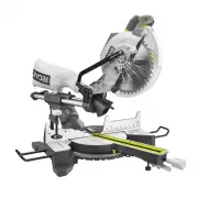
11 − English v FEATURES KNOW YOUR COMPOUND MITER SAW See Figures 1- 2. The safe use of this product requires an understanding of the information on the tool and in this operator’s manual as well as a knowledge of the project you are attempting. Before use of this product, familiarize yourself with a...
Page 12 - MITER
12 − English FEATURES MITER LOCK HANDLE See Figure 5. The miter lock handle securely locks the saw at desired miter angles. Tighten the handle to lock the saw in place. To release the saw, loosen the handle and squeeze the detent release lever. MITER SCALE The miter scale has index points provided a...
Page 13 - OFF
13 − English Fig. 6 PADLOCK SWITCH TRIGGER SWITCH TRIGGER SPINDLE LOCK BUTTON See Figure 6. The spindle lock button locks the spindle and stops the blade from rotating. Depress and hold the lock button while installing, changing, or removing blade. SWITCH TRIGGER See Figure 6. The saw will not start...
Page 14 - LOOSE PARTS LIST; TOOLS NEEDED
14 − English LOOSE PARTS LIST Fig. 8 Work Clamp Operator’s Manual (not shown) Dust Bag Table Extensions (2) WORK CLAMP DUST BAG TABLE EXTENSION TABLE EXTENSION The following items are included with the tool: WARNING: The use of attachments or accessories not listed might be hazardous and cou...
Page 15 - ASSEMBLY; UNPACKING
15 − English ASSEMBLY UNPACKING This product requires assembly. Carefully lift saw from the carton by the carrying handle and the saw base, and place it on a level work surface. WARNING: Do not use this product if any parts on the Loose Parts List are already assembled to your product when you unp...
Page 16 - MOUNTING HOLES
16 − English TRACE HOLES AT THESE LOCATIONS FOR HOLE PATTERN Fig. 9 MOUNTING SURFACE SAW BASE TRACE HOLES AT THESE LOCATIONS FOR HOLE PATTERN ASSEMBLY MOUNTING HOLES See Figure 9. WARNING: Before starting any cutting operation, clamp or bolt your miter saw to a workbench or an approved miter saw sta...
Page 17 - LOCK; USING THE DEPTH STOP; To use the depth stop:; LOCKING / UNLOCKING THE SAW ARM; To unlock and raise the saw arm:; DEPTH
17 − English Fig. 11 ASSEMBLY LOCK PIN “D” HANDLE Fig. 10 USING THE DEPTH STOP See Figure 10. When used, the depth stop limits the downward travel of the blade when cutting dadoes and other non-through cuts. To use the depth stop: Unplug the saw. If the saw is in storage or transport position, u...
Page 18 - DUST BAG; To install the work clamp:
18 − English ASSEMBLY DUST BAG See Figure 12. A dust bag is provided for use on this miter saw. It fits over the exhaust port on the back of the saw. NOTE: The exhaust port also accepts 1-1/4 in. vacuum hose. BLADE WRENCH See Figure 13. A blade wrench is included with this saw. One end of the wrench...
Page 19 - TABLE EXTENSIONS; To install table extensions:
19 − English ASSEMBLY TABLE EXTENSIONS See Figures 14 - 16. Table extensions have been provided for both the left and the right side of the saw. To install table extensions: Remove the screw from the underside of the base. Insert the ends of extension into the holes in the sides of the base. R...
Page 20 - TO INSTALL / REPLACE THE BLADE; Do not
20 − English ASSEMBLY TO INSTALL / REPLACE THE BLADE See Figures 17 - 18. The blade is shipped installed on this miter saw model. Instructions have been included for reference when changing or replacing blades. WARNING: A 12 in. blade is the maximum blade capacity of the saw. Never use a blade that ...
Page 21 - REMOVING/REPLACING THE THROAT PLATE; THROAT; ADJUSTING SUPPORT FOOT
21 − English ASSEMBLY CAUTION: Always install the blade with the blade teeth and the arrow printed on the side of the blade pointing down at the front of the saw. The direction of blade rotation is also stamped with an arrow on the upper blade guard. Tighten blade bolt securely. Replace blade bo...
Page 22 - SQUARING THE BLADE TO THE FENCE
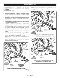
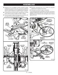
22 − English MITER LOCK HANDLE Fig. 20 VIEW OF BLADE SQUARE WITH FENCE SQUARE BLADE ASSEMBLY SQUARING THE BLADE TO THE FENCE See Figures 20 - 26. Unplug the saw. Pull the saw arm all the way down and engage the lock pin to hold the saw arm in transport position. Loosen the miter lock handle ap...
Page 24 - SQUARING THE BLADE TO THE MITER TABLE; Positive Stop
24 − English SQUARING THE BLADE TO THE MITER TABLE See Figures 27 - 29. Unplug the saw. Pull the saw arm all the way down and engage the lock pin to hold the saw arm in transport position. Loosen the miter lock handle approximately one-half turn and squeeze the detent release lever. Rotate t...
Page 25 - OPERATION; APPLICATIONS
25 − English OPERATION WARNING: Do not allow familiarity with tools to make you careless. Remember that a careless fraction of a second is sufficient to inflict serious injury. WARNING: Always wear eye protection with side shields marked to comply with ANSI Z87.1. Failure to do so could result in ob...
Page 26 - LED
26 − English CUTTING WITH YOUR COMPOUND MITER SAW WARNING: When using a work clamp, C-clamp, or other suitable clamp to secure your workpiece, clamp workpiece on one side of the blade only. The workpiece must remain free on one side of the blade to prevent the blade from binding in workpiece. The wo...
Page 27 - MITER CUT; CROSS CUT
27 − English TO MAKE NON-SLIDING CUTS WARNING: Securely tighten the slide lock knob when making any non-sliding cuts. Failure to tighten the knob could result in the saw head moving during the cutting operation. TO MITER CUT/CROSS CUT See Figures 30 - 31. A cross cut is made by cutting across the gr...
Page 28 - TO BEVEL CUT; TO COMPOUND MITER CUT
28 − English OPERATION Slowly lower the blade into and through the workpiece. Release the switch trigger and allow the saw blade to stop rotating before raising the blade out of workpiece and removing the workpiece from the miter table. TO BEVEL CUT See Figure 32. A bevel cut is made by cutting ...
Page 29 - COMPOUND MITER CUT
29 − English OPERATION Once the two correct settings for a particular cut have been obtained, always make a test cut in scrap material before making a finish cut in good material. NOTE: It may be necessary to adjust or remove the sliding miter fence to insure proper clearance prior to making the cut...
Page 30 - TO SUPPORT LONG WORKPIECES; NEVER
30 − English OPERATION TO SUPPORT LONG WORKPIECES See Figure 35. Long workpieces need extra supports. Supports, roller stand, or work surface level with the saw table should be placed along the workpiece so it does not sag. The support should let the workpiece lay flat on the base of the saw and wor...
Page 31 - MAKING AN AUXILIARY FENCE; MUST
31 − English AUXILIARY FENCE ALIGN BOARD WITH EDGE OF MITER TABLE OPERATION Release the switch trigger and allow the saw blade to stop rotating before raising the blade out of workpiece and removing the workpiece from miter table. NOTE: A cross cut is made by cutting across the grain of the workpi...
Page 32 - PITCH; CUTTING COMPOUND MITERS
32 − English OPERATION 4 PITCH OF SIDE NUMBER OF SIDES 0° 6 M- 45.00°B- 0.00° 5° 10° 15° 20° 25° 30° 35° 40° 45° 50° 55° 60° 65° 70° 75° 80° 85° 90° 5 7 8 9 10 M- 36.00°B- 0.00° M- 30.00°B- 0.00° M- 25.71°B- 0.00° M- 22.50°B- 0.00° M- 20.00°B- 0.00° M- 18.00°B- 0.00° Each B (Bevel) and M (Miter) Set...
Page 33 - CUTTING CROWN MOLDING; Bevel
33 − English OPERATION Fig. 39 When cutting crown molding by this method, the bevel angle should be set at 33.85 ° . The miter angle should be set at 31.6 ° either right or left, depending on the desired cut for the application. See the chart below for correct angle settings and correct positioning ...
Page 35 - RIGHT; CUTTING WARPED MATERIAL; WIDE
35 − English OPERATION Fig. 42 RIGHT CUTTING WARPED MATERIAL See Figures 42 - 43. When cutting warped material, always make sure it is positioned on the miter table with the convex side against the fence as shown in figure 42. If the warped material is positioned the wrong way as shown in figure 43,...
Page 36 - ADJUSTMENTS; PIVOT ADJUSTMENTS; AUTHORIZED SERVICE CENTER.; TO ADJUST THE BEVEL PIVOT; AUTHORIZED SERVICE; POSITIVE STOP ADJUSTMENTS
36 − English POSITIVE STOP ADJUSTMENT SCREW FOR 45 ° ANGLES ADJUSTMENTS WARNING: Before performing any adjustment, make sure the tool is unplugged from the power supply. Failure to heed this warning could result in serious personal injury. The compound miter saw has been adjusted at the factory for ...
Page 37 - MAINTENANCE; GENERAL MAINTENANCE; Proceed as follows when replacement is required:
37 − English MAINTENANCE WARNING: When servicing, use only identical replacement parts. Use of any other part can create a hazard or cause product damage. WARNING: Always wear eye protection with side shields marked to comply with ANSI Z87.1 during product operation. If operation is dusty, also wear...
Page 38 - CLEANING THE LED LENS
38 − English CLEANING THE LED LENS See Figure 48. Over time the LED light may become cloudy or dull. If this occurs, the LED lens may require cleaning. To clean the lens: Unplug the saw. Raise the saw arm. LED LENS COTTON SWAB Fig. 48 Remove the blade as described in the Assembly section. Ro...
Page 39 - NOTES
Page 40 - SÉCURITÉ DU LIEU DE TRAVAIL; Garder le lieu de travail propre et bien éclairé.; SÉCURITÉ ÉLECTRIQUE; RÈGLES DE SÉCURITÉ GÉNÉRALES; SÉCURITÉ PERSONNELLE
2 − Français AVERTISSEMENT : Lire les avertissements de sécurité, les instructions et les précisions et consulter les illustrations fournis avec cet outil électrique. Le fait de ne pas se conformer à l’ensemble des consignes présentées ci-dessous risque d’entraîner des décharges électriques, un ince...
Page 41 - Garder les outils bien affûtés et propres.; DÉPANNAGE; RÈGLES DE SÉCURITÉ DU SCIE À ONLGETS
3 − Français RÈGLES DE SÉCURITÉ GÉNÉRALES Avant de procéder à un réglage, à un changement d’accessoire ou au rangement de l’outil, débranchez la prise de la source d’alimentation ou, si le bloc-piles est amovible, retirez-le de l’outil. Ces mesures de sécurité préventives réduisent les risques de ...
Page 42 - Couper une seule pièce à travailler à la fois.; RÈGLES DE SÉCURITÉ SUPLÉMENTAIRES; Utiliser un cordon prolongateur adéquat.
4 − Français RÈGLES DE SÉCURITÉ DU SCIE À ONLGETS Ne pas utiliser la scie jusqu’à ce que la table soit libre de tous les outils, déchets de bois, etc., à l’exception de la pièce à travailler. Les petits débris, les morceaux de bois détachés ou les autres objets qui sont en contact avec la lame en ...
Page 44 - SYMBOLES
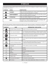
6 − Français SYMBOLES Certains des symboles ci-dessous peuvent être utilisés sur l’outil. Veiller à les étudier et à apprendre leur signification. Une interprétation correcte de ces symboles permettra d’utiliser l’outil plus efficacement et de réduire les risques. SYMBOLE NOM DÉSIGNATION / EXPLICATI...
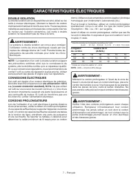
Page 45 - CARACTÉRISTIQUES ÉLECTRIQUES; DOUBLE ISOLATION; une alimentation 120 V,; CORDONS PROLONGATEURS; Longueur
7 − Français CARACTÉRISTIQUES ÉLECTRIQUES DOUBLE ISOLATION La double isolation est un dispositif de sécurité utilisé sur les outils à moteur électriques, éliminant le besoin de cordon d’alimentation habituel à trois fils avec terre. Toutes les pièces métalliques exposées sont isolées des composants ...
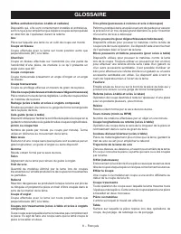
Page 46 - GLOSSAIRE
8 − Français GLOSSAIRE Trou pilote (perceuses à colonne et scie à découper) Petit trou pratiqué dans une pièce servant de guide pour assurer la précision d’un trou de plus grand diamètre ou pour l’insertion d’une lame de scie à découper. Blocs poussoirs (pour dégauchisseuses/raboteuses) Dispositifs ...
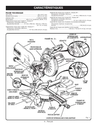
Page 47 - CARACTÉRISTIQUES; FICHE TECHNIQUE; CLÉ DE
9 − Français CARACTÉRISTIQUES FICHE TECHNIQUE Trou d’axe .................................................................... 25,4 mm (1 po) Diamètre de la lame.................................................... 305 mm (12 po) Vitesse à vide ............................................................
Page 49 - BOUTON DE VERROUILLAGE DE BISEAU
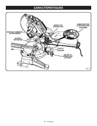
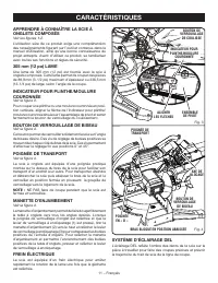
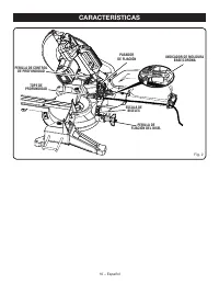
11 − Français CARACTÉRISTIQUES APPRENDRE À CONNAÎTRE LA SCIE À ONGLETS COMPOSÉS Voir les figures 1-2. L’utilisation sûre de ce produit exige une compréhension des renseignements figurant sur l’outil et contenus dans le manuel d’utilisation, ainsi qu’une bonne connaissance du projet entrepris. Avant ...
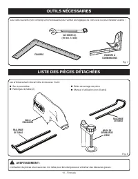
Page 52 - LISTE DES PIÈCES DÉTACHÉES; OUTILS NÉCESSAIRES
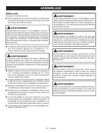
14 − Français LISTE DES PIÈCES DÉTACHÉES Fig. 8 Bride de serrage de pièce Manuel d’utilisation (non illustré) Sac à pouissière Rallonges de table (2) Les articles suivant doivent être inclus avec l’outil: AVERTISSEMENT : L’utilisation de pièces et accessoires non listés peut être dangereux e...
Page 53 - ASSEMBLAGE; DÉBALLAGE
15 − Français ASSEMBLAGE DÉBALLAGE This product requires assembly. Sortir soigneusement la scie du carton en la tenant par la poignée de transport et la base de la scie, et la poser sur un plan de travail horizontal. AVERTISSEMENT : Ne pas utiliser le produit si, en le déballant, vous con-statez q...
Page 54 - TROUS DE FIXATION
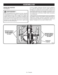
16 − Français TRACER DES TROUS À CES EMPLACEMENTS SELON LE GABARIT DE TROUS SURFACE DE FIXATION TRACER DES TROUS À CES EMPLACEMENTS SELON LE GABARIT DE TROUS Fig. 9 BASE DE LA SCIE TROUS DE FIXATION Voir la figure 9. AVERTISSEMENT : Avant d’entreprendre toute opération de coupe, assujettir ou boulon...
Page 55 - UTILISATION DU GUIDE DE PROFONDEUR; Pour utiliser le guide de profondeur :; VERROUILLAGE/DÉVERROUILLAGE DU BRAS; Pour déverrouiller et relever le bras de la scie :; BOUTON DE COMMANDE; GOUPILLE DE
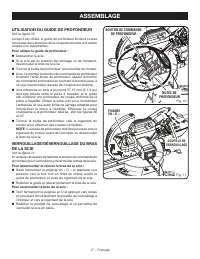
17 − Français ASSEMBLAGE UTILISATION DU GUIDE DE PROFONDEUR Voir la figure 10. Lorsqu’il est utilisé, le guide de profondeur limite la course vers le bas de la lame lors de la coupe de rainures et d’autres coupes non traversantes. Pour utiliser le guide de profondeur : Débrancher la scie Si la s...
Page 56 - SAC À POUSSIÈRE; CLÉ DE LAME; Installation de la bride de serrage de pièce :
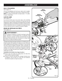
18 − Français ASSEMBLAGE SAC À POUSSIÈRE Voir la figure 12. Un sac à poussières est fourni avec cette scie à onglets. Il s’adapte sur l’orifice de sortie situé à l’arrière de la scie. NOTE : Le orifice d’évacuation accepte aussi 1-1/4 dans. le tuyau d’aspirateur. CLÉ DE LAME Voir la figure 13. La sc...
Page 57 - RALLONGES DE TABLE; Pour l’installer les rallonges de table :; VIS DE RALLONGE
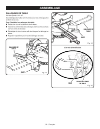
19 − Français ASSEMBLAGE RALLONGES DE TABLE Voir les figures 14 à 16. Des rallonges de table sont fournies pour les côtés gauche et droit de la scie. Pour l’installer les rallonges de table : Retirer les vis de la dessous de la base. Insérer les extrémités des rallonges dans les trous situés sur...
Page 58 - INSTALLATION / REMPLACEMENT DE LA
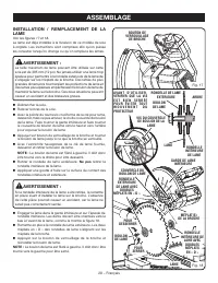
20 − Français ASSEMBLAGE INSTALLATION / REMPLACEMENT DE LA LAME Voir les figures 17 et 18. La lame est déjà installée à la livraison de ce modèle de scie à onglets. Les instructions sont comprises afin qu’on puisse les consulter lorsqu’on change ou qu’on remplace les lames. AVERTISSEMENT : La taille...
Page 59 - PLAQUE À; RÉGLAGE DU PIED DE SUPPORT; Ne jamais utiliser la scie
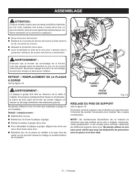
21 − Français ASSEMBLAGE ATTENTION : Toujours installer la lame avec les dents et la flèche imprimée sur son côté, orientées vers le bas à l’avant de la scie. Le sens de rotation de la lame est également représenté par une flèche estampée sur la protection supérieure. Serrer le boulon fermement. ...
Page 62 - Réglage
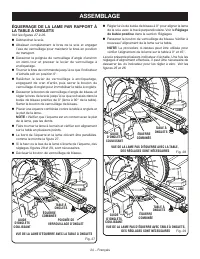
24 − Français VUE DE LA LAME D’ÉQUERRE AVEC LA TABLE À ONGLETS TABLE À ONGLETS POIGNÉE DE VERROUILLAGE D’ONGLET ÉQUERRE COMBINÉE LAME GUIDE D’ONGLETS COULISSANT ASSEMBLAGE ÉQUERRAGE DE LA LAME PAR RAPPORT À LA TABLE À ONGLETS Voir les figures 27 à 29. Débrancher la scie. Abaisser complètement le...
Page 63 - UTILISATION
25 − Français UTILISATION AVERTISSEMENT : Ne pas laisser la familiarité avec l’outil faire oublier la prudence. Ne pas oublier qu’une fraction de seconde d’inattention peut entraîner des blessures graves. AVERTISSEMENT : Toujours porter une protection oculaire certifiée conforme à la norme ANSI Z87....
Page 64 - TRAVAUX DE COUPE AVEC LA SCIE À ONGLETS; INTERRUPTEUR
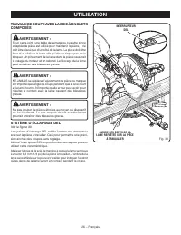
26 − Français UTILISATION TRAVAUX DE COUPE AVEC LA SCIE À ONGLETS COMPOSÉS AVERTISSEMENT : Si un serre-joint, une bride de serrage ou ou autre pince adaptée de pièce est utilisé pour maintenir la pièce, il ne doit être placé que d’un côté de la lame. La pièce doit être libre d’un côté de la lame afi...
Page 66 - COUPE EN BISEAU; COUPE D’ONGLET COMPOSÉ; BRIDE DE
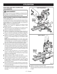
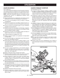
28 − Français UTILISATION COUPE EN BISEAU Voir le figure 32. Une coupe en biseau est réalisée en travers du grain de la pièce, avec la lame en biais. Pour effectuer une coupe en biseau droite, la table à onglets doit être réglée sur 0° et la lame entre 0° et 45°. NOTE : Il peut être nécessaire d’aju...
Page 68 - SUPPORT DE PIÈCES LONGUES
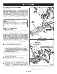
30 − Français UTILISATION SUPPORT DE PIÈCES LONGUES Voir la figure 35. Les pièces longues nécessitent un support additionnel. Les supports, un support à rouleau, ou une surface de travail de niveau avec la table de la scie doivent être placés sous la pièce, de manière à ce qu’elle ne fléchisse pas. ...
Page 69 - Pour fixer le guide auxiliaire à la scie :
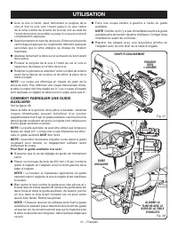
31 − Français UTILISATION Avec la scie à l’arrêt, saisir fermement la poignée de la scie et tirer la scie vers l’avant jusqu’à ce que l’arbre de la lame (centre de la lame de la scie) soit au-delà de l’avant de la pièce à travailler ou jusqu’à ce que la scie soit complètement déployée. Saisir fe...
Page 70 - ANGLE; COUPE D’ONGLETS COMPOSÉS
32 − Français UTILISATION 4 ANGLE DE CÔTÉ NOMBRE DE CÔTÉS 0° 6 5° 10° 15° 20° 25° 30° 35° 40° 45° 50° 55° 60° 65° 70° 75° 80° 85° 90° 5 7 8 9 10 Chaque angle B (biseau) et M (onglet) est indiquée au 0,005 ème de degré le plus proche. RÉGLAGES D’ANGLES COMPOSÉS POUR LES CONSTRUCTIONS COURANTES COUPE ...
Page 71 - COUPE DE MOULURE COURONNÉE
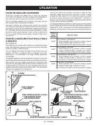
33 − Français UTILISATION Lors de la coupe d’une moulure couronnée à l’aide de cette méthode, l’angle de biseau doit être réglé à 33,85°. L’angle d’onglet doit être réglé à 31,6° à droite ou à gauche, suivant le sens de coupe nécessaire pour l’application. Consulter le tableau ci-dessous pour les ré...
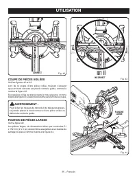
Page 73 - COUPE DE PIÈCES VOILÉES; PLANCHE
35 − Français UTILISATION COUPE DE PIÈCES VOILÉES Voir les figures 42 et 43. Lors de la coupe d’une pièce voilée, toujours s’assurer que son bord convexe est placé contre le guide, comme le montre la figure 42. Si une pièce voilée est placée dans le mauvais sens, comme illustré à la figure 43, elle ...
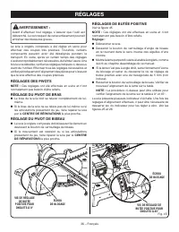
Page 74 - RÉGLAGES; RÉGLAGES DES PIVOTS; CENTRE DE RÉPARATIONS; RÉGLAGE DU PIVOT DE BISEAU; CENTRE; RÉGLAGES DE BUTÉE POSITIVE
36 − Français RÉGLAGES AVERTISSEMENT : Avant d’effectuer tout réglage, s’assurer que l’outil est débranché. Le non respect de cet avertissement pourrait entraîner des blessures graves. La scie à onglets composés a été réglée en usine pour effectuer des coupes très précises. Toutefois, certains compo...
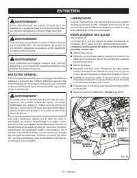
Page 75 - ENTRETIEN; ENTRETIEN GÉNÉRAL
37 − Français ENTRETIEN AVERTISSEMENT : Utiliser exclusivement des pièces d’origine pour les réparations. L’usage de toute autre pièce pourrait créer une situation dangereuse ou endommager le produit. AVERTISSEMENT : Toujours porter une protection oculaire certifiée conforme à la norme ANSI Z87.1 lo...
Page 76 - NETTOYAGE DE LA LENTILLE DEL; LENTILLE
38 − Français NETTOYAGE DE LA LENTILLE DEL Voir la figure 48. Avec le temps, il est possible que la lumière à la DEL devienne embrouillée ou diffuse. Si c’est le cas, il est possible que la lentille à la DEL doive être nettoyée. Pour nettoyer la lentille : Débrancher la scie. Soulever le bras de...
Page 78 - REGLAS DE SEGURIDAD GENERALES; ÁREA DE TRABAJO; Mantenga limpia y bien iluminada el área de trabajo.; SEGURIDAD ELÉCTRICA
2 − Español REGLAS DE SEGURIDAD GENERALES ADVERTENCIA: L e a t o d a s l a s a d v e r t e n c i a s , i n s t r u c c i o n e s , ilustraciones y especificaciones proporcionadas con esta herramienta eléctrica. No seguir las instrucciones indicadas a continuación puede provocar descargas eléctricas,...
Page 79 - Mantenga las herramientas de corte afiladas y limpias.; SERVICIO; de trabajo hacia la hoja o corte sin usar las manos
3 − Español REGLAS DE SEGURIDAD GENERALES REGLAS DE SEGURIDAD SIERRA INGLETEADORA La herramienta eléctrica adecuada efectúa mejor y de manera más segura el trabajo, si además se maneja a la velocidad para la que está diseñada. No utilice la herramienta si el interruptor no enciende o no apaga. Cua...
Page 80 - REGLAS DE SEGURIDAD SIERRA INGLETEADORA; Corte solo una pieza de trabajo por vez.; ADVERTENCIAS DE SEGURIDAD ADICIONALES; Use un cordón de extensión adecuado.
4 − Español REGLAS DE SEGURIDAD SIERRA INGLETEADORA corte. No debe haber clavos ni objetos extraños en la pieza de trabajo. No use la hoja hasta que la mesa esté libre de cualquier otra herramienta, desechos de madera, etc. Solo debe estar la pieza de trabajo. En caso de haber desechos pequeños, p...
Page 82 - SÍMBOLOS; SÍMBOLO
6 − Español SÍMBOLOS Es posible que se empleen en esta herramienta algunos de los siguientes símbolos. Le suplicamos estudiarlos y aprender su significado. Una correcta interpretación de estos símbolos le permitirá utilizar mejor y de manera más segura la herramienta. Alerta de seguridad Indica un p...
Page 83 - ASPECTOS ELÉCTRICOS; DOBLE AISLAMIENTO; un suministro; CORDONES DE EXTENSIÓN; Longitud
7 − Español ASPECTOS ELÉCTRICOS DOBLE AISLAMIENTO El doble aislamiento es una característica de seguridad de las herramientas eléctricas, la cual elimina la necesidad de usar el típico cordón eléctrico de tres conductores con conexión a tierra. Todas las partes metálicas expuestas están aisladas de ...
Page 84 - GLOSARIO DE TÉRMINOS
8 − Español GLOSARIO DE TÉRMINOS Este es un corte en el cual la hoja no corta la pieza de trabajo en dos pedazos. Agujero guía (taladradoras de columna y sierras caladoras) Es un agujero pequeño taladrado en una pieza de trabajo, el cual sirve como guía para taladrar con precisión agujeros más grand...
Page 85 - CARACTERÍSTICAS; ESPECIFICACIONES DEL PRODUCTO; LLAVE
9 − Español CARACTERÍSTICAS ESPECIFICACIONES DEL PRODUCTO Orificio del eje ........................................................... 25,4 mm (1 pulg.) Diámetro de la hoja ................................................. 305 mm (12 pulg.) Velocidad en vacío ...........................................
Page 88 - MANIJA DE FIJACIÓN DE INGLETE; GUÍAS TELESCÓPICA
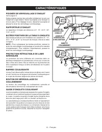
12 − Español CARACTERÍSTICAS MANIJA DE FIJACIÓN DE INGLETE Vea la figura 5. La manija de fijación de inglete asegura firmemente la sierra en los ángulos de inglete deseados. Ajuste el mango para fijar la sierra en su lugar. Para liberar la sierra, afloje el mango y apriete la palanca de detención de...
Page 89 - BOTÓN DEL SEGURO DEL HUSILLO
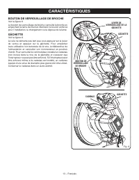
13 − Español CARACTERÍSTICAS BOTÓN DEL SEGURO DEL HUSILLO Vea la figura 6. El botón del seguro del husillo sirve para asegurar el husillo y impedir el giro de la hoja. Oprima y no suelte el botón del seguro del husillo mientras instala, cambia o desmonta la hoja. GATILLO DEL INTERRUPTOR Vea la figur...
Page 90 - LISTA DE PIEZAS SUELTAS; HERRAMIENTAS NECESARIAS
14 − Español LISTA DE PIEZAS SUELTAS Fig. 8 Prensa de trabajo Manual del operador (no se muestra) Saco captapolvo Extensiones de la mesa (2) Vienen incluidos los siguientes artículos con la herramienta: ADVERTENCIA: El empleo de aditamentos o accesorios no enumerados arriba podría ser peligr...
Page 91 - ARMADO; DESEMPAQUETADO
15 − Español ARMADO DESEMPAQUETADO Este producto requiere armarse. Levante cuidadosamente de la caja la sierra sujetándola del mango de acarreo y de la base, y colóquela sobre una superficie de trabajo a nivel. ADVERTENCIA: No utilice este producto si alguna pieza incluida en la lista de piezas su...
Page 92 - AGUJEROS DE MONTAJE
16 − Español SEÑALE EL CENTRO DE LOS AGUJEROS EN ESTOS LUGARES SEÑALE EL CENTRO DE LOS AGUJEROS EN ESTOS LUGARES SUPERFICIE DE MONTAJE Fig. 9 BASE DE LA SIERRA ARMADO AGUJEROS DE MONTAJE Vea la figura 9. ADVERTENCIA: Antes de iniciar cualquier operación de corte, sujete con prensa(s) o atornille la ...
Page 93 - USO EL TOPE DE PROFUNDIDAD; Para usar el tope de profundidad:; PROCEDIMIENTO DE TRABA Y DESTRABA EL; MANGO; PERILLA DE; PASADOR DE
17 − Español ARMADO USO EL TOPE DE PROFUNDIDAD Vea la figura 10. Su uso limita el descenso de la hoja durante cortes de ranura y demás tipos de corte no pasante. Para usar el tope de profundidad: Desconecte la sierra Si la sierra está en posición de almacenamiento o trans - porte, destrabe el br...
Page 94 - SACO CAPTAPOLVO; Para instalar la prensa de trabajo:
18 − Español ARMADO SACO CAPTAPOLVO Vea la figura 12. Se suministra un saco captapolvo para utilizarse con la sierra ingleteadora. Se acopla en la abertura de salida del aserrín, en la parte posterior de la sierra. NOTA: El orificio de escape acepta también 1-1/4 en. saco captapolvo. LLAVE DE LA HOJ...
Page 95 - EXTENSIONES DE LA MESA; Para asegurar las extensiones de la mesa:
19 − Español ARMADO EXTENSIONES DE LA MESA Vea las figuras 14 a 16. Se proporcionan extensiones de la mesa para los lados izquierdo y derecho de la sierra. Para asegurar las extensiones de la mesa: Retire los tornillos de la superficie inferior de la base. Inserte los extremos de la extensión de...
Page 96 - PARA INSTALAR O REEMPLAZAR LA HOJA
20 − Español ARMADO PARA INSTALAR O REEMPLAZAR LA HOJA Vea las figuras 17 y 18. La hoja viene instalada en este modelo de sierra ingleteadora. Para su referencia, se incluyen instrucciones para cambiar o reemplazar las hojas. ADVERTENCIA: La sierra tiene capacidad para hojas hasta de un diámetro de ...
Page 97 - EXTRACCIÓN / REEMPLAZO DE LA PLACA DE; PLACA DE LA; PARA AJUSTAR PIED DE SUPPORT; Nunca
21 − Español ARMADO PRECAUCIÓN: Siempre instale la hoja con los dientes de la misma y la flecha impresa en el costado de la hoja apuntando hacia abajo en la parte frontal de la sierra. El sentido de giro de la hoja también está impreso en forma de flecha en la protección superior de la hoja. Aprie...
Page 98 - ESCUADRADO DE LA HOJA CON LA MESA DE
22 − Español GUÍA DE INGLETES DESLIZABLE VISTA A DE LA HOJA A ESCUADRA CON LA GUÍA HOJA MANIJA DE FIJACIÓN DE INGLETE ESCUADRA MESA DE INGLETES Fig. 20 ARMADO ESCUADRADO DE LA HOJA CON LA MESA DE INGLETES Vea las figuras 20 a 26. Desconecte la sierra. Tire del brazo de la sierra completamente ha...
Page 100 - INGLETES; Ajuste de los topes
24 − Español VISTA CORRECTA DE LA HOJA A ESCUADRA CON LA MESA DE INGLETES ESCUADRA DE COMBINACIÓN MESA DE INGLETES MANIJA DE FIJACIÓN DE INGLETE GUÍA DE INGLETES DESLIZABLE ARMADO INGLETES Vea las figuras 27 a 29. Desconecte la sierra. Tire del brazo de la sierra completamente hacia abajo y enga...
Page 101 - FUNCIONAMIENTO
25 − Español FUNCIONAMIENTO ADVERTENCIA: No permita que su familarización con las herramientas lo vuelva descuidado. Tenga presente que un descuido de un instante es suficiente para causar una lesión grave. ADVERTENCIA: Siempre póngase protección ocular con la marca de cumplimiento de la norma ANSI ...
Page 102 - INTERRUPTOR
26 − Español PROCEDIMIENTO DE CORTE CON LA SIERRA INGLETEADORA COMPUESTA ADVERTENCIA: Al usar la prensa de trabajo, prensa en c, u otra prensa adecuada para asegurar la pieza, sujete ésta sólo en un lado de la hoja. La pieza de trabajo debe quedar libre en un lado de la hoja para evitar que ésta se ...
Page 104 - PARA CORTAR A BISEL; CORTE EN BISEL; PARA EFECTUAR UN CORTE A INGLETE; PRENSA DE
28 − Español FUNCIONAMIENTO PARA CORTAR A BISEL Vea la figura 32. Un corte en bisel se efectúa cortando a través de la fibra de la pieza de trabajo con la hoja en ángulo con dicha pieza. Un corte en bisel recto se efectúa con la mesa de ingletes en la posición de cero grados y la hoja a un ángulo en...
Page 105 - CORTE EN BISEL COMBINADO
29 − Español FUNCIONAMIENTO Deslice el cabezal de la sierra hacia su posición más trasera y ajuste la perilla de fijación de la corredera en forma segura. Extraiga el pasador de seguridad y levante el brazo de la sierra a su máxima altura. Afloje la perilla de fijación de inglete aproximadamen...
Page 106 - PARA APOYAR LAS PIEZAS DE TRABAJO
30 − Español FUNCIONAMIENTO PARA APOYAR LAS PIEZAS DE TRABAJO LARGAS Vea la figura 35. Las piezas de trabajo largas necesitan soportes extra. Los soportes base con ruedas, o superficie de trabajo nivelada con la sierra de mesa deben colocarse a lo largo de la pieza de trabajo de manera que no se pan...
Page 107 - FORMA DE HACER UNA GUÍA AUXILIAR
31 − Español FUNCIONAMIENTO delantera de la pieza de trabajo o hasta que la sierra esté completamente extendida. Sujete firmemente el mango de la sierra. Oprima la palanca del seguro del gatillo y luego oprima el gatillo. Permita transcurrir varios segundos para que la hoja alcance su velocidad má...
Page 108 - AJUSTES DE ÁNGULOS COMBINADOS PARA ESTRUCTURAS COMUNES; CÓMO EFECTUAR CORTES A INGLETE COMBINADOS; INCLINACIÓN
32 − Español FUNCIONAMIENTO Cada cantidad, B (bisel) y M (inglete), se da con una tolerancia de 0,005°. AJUSTES DE ÁNGULOS COMBINADOS PARA ESTRUCTURAS COMUNES CÓMO EFECTUAR CORTES A INGLETE COMBINADOS Como ayuda para realizar los ajustes correctos, se suministra la siguiente tabla de ángulos combina...
Page 109 - CÓMO CORTAR MOLDURAS DE CORONA; Bisel
33 − Español FUNCIONAMIENTO bisel debe fijarse a 33,85°. El ángulo de inglete debe fijarse a 31,6°, a la derecha o izquierda, según el corte deseado para cada aplicación en particular. En la tabla mostrada a continu - ación encontrará los ajustes correctos de los ángulos y la colo - cación correcta ...
Page 110 - ENCAJE DE MOLDURA EN CORONA CONTRA
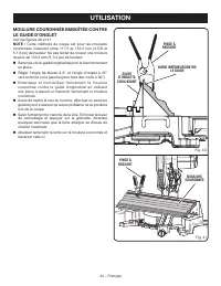
34 − Español FUNCIONAMIENTO ENCAJE DE MOLDURA EN CORONA CONTRA LA GUÍA DE INGLETE Vea las figuras 40 y 41. NOTA: Este método de corte es para las molduras de corona de entre 117,5 mm (4-5/8 pulg.) y 133,3 mm (5-1/4 pulg.) de altura. No intente cortar una moldura de más de 133,3 mm (5-1/4 pulg.) de a...
Page 111 - CÓMO CORTAR MATERIAL DISTORSIONADO; FORMA CORRECTA
35 − Español FUNCIONAMIENTO CÓMO CORTAR MATERIAL DISTORSIONADO Vea las figuras 42 y 43. Al cortar material distorsionado, siempre asegúrese de que esté colocado en la mesa de ingletes con el lado convexo contra la guía, como se muestra en la figura 42. Si se coloca de una forma equivocada el materia...
Page 112 - AJUSTES; AJUSTES DE LOS PIVOTES; AJUSTE DEL PIVOTE DE BISEL; CENTRO DE SERVICIO AUTORIZADO; AJUSTE DE LOS TOPES
36 − Español AJUSTES ADVERTENCIA: Antes de efectuar cualquier ajuste, asegúrese de que la herramienta esté desconectada del suministro de corriente. La inobservancia de esta advertencia podría causar lesiones corporales serias. La sierra ingleteadora combinada ha sido ajustada en la fábrica para pro...
Page 113 - MANTENIMIENTO; MANTENIMIENTO GENERAL; Proceda como sigue cuando se requiera un reemplazo:
37 − Español MANTENIMIENTO ADVERTENCIA: Al dar servicio a la unidad, utilice sólo piezas de repuesto idénticas. El empleo de piezas diferentes puede presentar un peligro o causar daños al producto. ADVERTENCIA: Siempre póngase protección ocular con la marca de cumplimiento de la norma ANSI Z87.1. Si...
Page 114 - LIMPIEZA DE LA LENTE LED; Para limpiar la lente:; LENTE
38 − Español LIMPIEZA DE LA LENTE LED Vea la figura 48. Con el tiempo, es posible que la luz LED se vea opacada o tenue. Si ocurre esto, es posible que la lente LED deba limpiarse. Para limpiar la lente: Desenchufe la sierra. Eleve el brazo de la sierra. Fig. 48 Quite la hoja como se describe ...
Page 115 - NOTAS
Page 116 - OPERATOR’S MANUAL/SLIDING COMPOUND MITER SAW
99500061712-7-18 (REV:04) OPERATOR’S MANUAL/SLIDING COMPOUND MITER SAW MANUEL D’UTILISATION/SCIE À ONGLETS COMBINÉS COULISSANTEMANUAL DEL OPERADOR/SIERRA INGLETEADORA COMPUESTA DESLIZANTE TSS121/TSS121T ONE WORLD TECHNOLOGIES, INC. P.O. Box 1288, Anderson, SC 29622 • Phone 1-800-525-2579 États-Unis,...