Page 2 - GENERAL SAFETY RULES; Save all warnings and instructions for future reference.; WORK AREA SAFETY; Keep work area clean and well lit.; ELECTRICAL SAFETY; Do not expose power tools to rain or wet conditions.; PERSONAL SAFETY
2 − English GENERAL SAFETY RULES WARNING: Read all safety warnings, instructions, illustrations and specifications provided with this power tool. Failure to follow all instructions listed below may result in electric shock, fire and/or serious injury. Save all warnings and instructions for future re...
Page 3 - Keep cutting tools sharp and clean.; BATTERY TOOL USE AND CARE; Use battery only with charger listed.; SERVICE; Never service damaged battery packs.
3 − English GENERAL SAFETY RULES Keep cutting tools sharp and clean. Properly maintained cutting tools with sharp cutting edges are less likely to bind and are easier to control. Use the power tool, accessories and tool bits etc. in accordance with these instructions, taking into account the wor...
Page 4 - MITER SAW SPECIFIC SAFETY RULES; the workpiece into the blade or cut ”freehand” in any; Cut only one workpiece at a time.; Save these instructions.
4 − English MITER SAW SPECIFIC SAFETY RULES Miter saws are intended to cut wood or wood-like products, they cannot be used with abrasive cut-off wheels for cutting ferrous material such as bars, rods, studs, etc. Abrasive dust causes moving parts such as the lower guard to jam. Sparks from abrasiv...
Page 5 - ADDITIONAL SAFETY RULES
5 − English ADDITIONAL SAFETY RULES Inspect tool cords periodically. If damaged, have re- paired by a qualified service technician at an authorized service facility. Repair or replace a damaged or worn cord immediately. Stay constantly aware of cord location and keep it well away from the rotating...
Page 6 - SYMBOLS
6 − English Some of the following symbols may be used on this tool. Please study them and learn their meaning. Proper interpreta-tion of these symbols will allow you to operate the tool better and safer. SYMBOL NAME DESIGNATION/EXPLANATION Safety Alert Indicates a potential personal injury hazard. R...
Page 7 - GLOSSARY OF TERMS
7 − English GLOSSARY OF TERMS Pilot Hole (drill presses and scroll saws) A small hole drilled in a workpiece that serves as a guide for drilling large holes accurately or for insertion of a scroll saw blade. Push Blocks (jointer planers) Device used to feed the workpiece over the jointer planer cutt...
Page 8 - FEATURES; PRODUCT SPECIFICATIONS; DEPTH STOP
8 − English FEATURES PRODUCT SPECIFICATIONS Arbor Hole ................................................................. 5/8 in.Blade Diameter ............................................................10 in.No Load Speed ........................................4,100/min. (RPM)Input ..................
Page 11 - LOOSE PARTS LIST; TOOLS NEEDED
11 − English LOOSE PARTS LIST Fig. 6 Table Extensions (2) Work Clamp Operator’s Manual (not shown) Blade Wrench Carrying Handle Dust Bag WORK CLAMP DUST BAG RIGHT TABLE EXTENSION LEFT TABLE EXTENSION The following items are included with the tool: WARNING: The use of attachments or acces...
Page 12 - UNPACKING; ASSEMBLY
12 − English WARNING: If any parts are damaged or missing do not operate this product until the parts are replaced. Use of this product with damaged or missing parts could result in serious personal injury. WARNING: Do not attempt to modify this product or create acces-sories not recommended for use...
Page 13 - LOCK NUTS
13 − English Fig. 8 TRACE HOLES AT THESE LOCATIONS FOR HOLE PATTERN Fig. 7 MOUNTING SURFACE SAW BASE TRACE HOLES AT THESE LOCATIONS FOR HOLE PATTERN MOUNTING HOLES See Figure 7. WARNING: Before starting any cutting operation, clamp or bolt your miter saw to a workbench or an approved miter saw stand...
Page 14 - DEPTH; USING THE DEPTH STOP; To use the depth stop:; LOCKING/UNLOCKING THE SAW ARM; To unlock and raise the saw arm:
14 − English Fig. 10 LOCK PIN “D” HANDLE Fig. 9 DEPTH CONTROL KNOB DEPTH STOP ASSEMBLY USING THE DEPTH STOP See Figure 9. When used, the depth stop limits the downward travel of the blade when cutting dadoes and other non-through cuts. To use the depth stop: Remove the battery. If the saw is in ...
Page 15 - To install the work clamp:
15 − English DUST BAG See Figure 11. A dust bag is provided for use on this miter saw. It fits over the exhaust port on the back of the saw. NOTE: The exhaust port also accepts 1-1/4 in. vacuum hose. BLADE WRENCH See Figure 12. A blade wrench is included with this saw. One end of the wrench is a phi...
Page 16 - TABLE EXTENSIONS; To install table extensions:
16 − English Fig. 13 BOLT HOLE BOLT BOLT LOCK NUT LOCK NUT BASE SAW VIEWED FROM BOTTOM ASSEMBLY TABLE EXTENSIONS See Figures 13 - 15. Table extensions have been provided for both the left and the right side of the saw. The left and right extensions will only fit properly one way. Be sure the front e...
Page 17 - TO INSTALL/REPLACE THE BLADE; Do not
17 − English ASSEMBLY TO INSTALL/REPLACE THE BLADE See Figures 16 - 17. The blade is shipped installed on this miter saw model. Instructions have been included for reference when chang-ing or replacing blades. WARNING: A 10 in. blade is the maximum blade capacity of the saw. Never use a blade that i...
Page 18 - Never operate the saw without all guards securely
18 − English CAUTION: Always install the blade with the blade teeth and the arrow printed on the side of the blade pointing down at the front of the saw. The direction of blade rotation is also stamped with an arrow on the upper blade guard. Tighten blade bolt securely. Replace blade bolt cover ...
Page 19 - SQUARING THE BLADE TO THE FENCE
19 − English Fig. 19 MITER LOCK HANDLE MITER TABLE MITER TABLE MITER TABLE VIEW OF BLADE SQUARE WITH FENCE SQUARE SQUARE SQUARE MITER FENCE MITER FENCE MITER FENCE BLADE BLADE BLADE SQUARING THE BLADE TO THE FENCE See Figures 19 - 24. Remove the battery. Pull the saw arm all the way down and eng...
Page 21 - SQUARING THE BLADE TO THE MITER TABLE; Positive Stop Adjust-
21 − English Fig. 25 CORRECT VIEW OF BLADE SQUARE WITH MITER TABLE COMBINATION SQUARE COMBINATION SQUARE COMBINATION SQUARE SQUARING THE BLADE TO THE MITER TABLE See Figures 25 - 27. Remove the battery. Pull the saw arm all the way down and engage the lock pin to hold the saw arm in transport po...
Page 22 - OPERATION; APPLICATIONS; BATTERY
22 − English Fig. 28 WARNING: To avoid serious personal injury, keep hands outside the no hands zone, at least 4 in. (100 mm) from the blade. Never perform any cutting operation freehand (without holding workpiece against the fence). The blade could grab the workpiece if it slips or twists. NOTICE: ...
Page 23 - LED LIGHTING SYSTEM; SHADOW OF BLADE
23 − English CUTTING WITH YOUR COMPOUND MITER SAW WARNING: When using a work clamp or C-clamp to secure your workpiece, clamp workpiece on one side of the blade only. The workpiece must remain free on one side of the blade to prevent the blade from binding in workpiece. The workpiece binding the bla...
Page 24 - MITER CUT; CROSS CUT; TO MAKE NON-SLIDING CUTS
24 − English MITER CUT WORK CLAMP PARTIAL SLIDING FENCE CROSS CUT Fig. 30 WORK CLAMP Fig. 31 OPERATION TO MAKE NON-SLIDING CUTS WARNING: Securely tighten the slide lock knob when making any non-sliding cuts. Failure to tighten the knob could result in the saw head moving during the cutting operation...
Page 25 - TO BEVEL CUT
25 − English OPERATION Release the switch trigger and allow the saw blade to stop rotating before raising the blade out of workpiece and removing the workpiece from the miter table. TO BEVEL CUT See Figure 32. A bevel cut is made by cutting across the grain of the workpiece with the blade angled t...
Page 26 - TO COMPOUND MITER CUT
26 − English Fig. 33 C-CLAMP COMPOUND MITER CUT Fig. 34 45 ° X 45 ° COMPOUND MITER CUT OPERATION TO COMPOUND MITER CUT See Figures 33 - 34. A compound miter cut is a cut made using a miter angle and a bevel angle at the same time. This type of cut is used to make picture frames, cut molding, make bo...
Page 27 - TO SUPPORT LONG WORKPIECES; NEVER
27 − English OPERATION Grasp the stock firmly with one hand and secure it against the fence. Use the work clamp, C-clamp, or other suitable clamp to secure the workpiece when possible. Before turning on the saw, perform a dry run of the cutting operation just to make sure that no problems will o...
Page 28 - MAKING AN AUXILIARY FENCE; MUST
28 − English OPERATION Grasp the stock firmly with one hand and secure it against the fence. Use the work clamp, C-clamp, or other suitable clamp to secure the workpiece when possible. Before turning on the saw, perform a dry run of the cut- ting operation to make sure that no problems will occu...
Page 29 - CUTTING COMPOUND MITERS; PITCH
29 − English OPERATION CUTTING COMPOUND MITERS To aid in making the correct settings, the compound angle setting chart below has been provided. Since compound cuts are the most difficult to accurately obtain, trial cuts should be made in scrap material, and much thought and planning made, prior to m...
Page 30 - Bevel; CUTTING CROWN MOLDING
30 − English OPERATION Fig. 39 31.6 ° either right or left, depending on the desired cut for the application. See the chart below for correct angle settings and correct positioning of crown molding on miter table.The settings in the chart below can be used for cutting All Standard (U.S.) crown moldi...
Page 32 - CUTTING WARPED MATERIAL; RIGHT
32 − English OPERATION CUTTING WARPED MATERIAL See Figures 42 - 43. When cutting warped material, always make sure it is posi-tioned on the miter table with the convex side against the fence as shown in figure 42. If the warped material is positioned the wrong way as shown in figure 43, it will pinc...
Page 33 - ADJUSTMENTS; PIVOT ADJUSTMENTS; AUTHORIZED SERVICE CENTER.; TO ADJUST THE BEVEL PIVOT; AUTHORIZED SERVICE; POSITIVE STOP ADJUSTMENTS
33 − English ADJUSTMENTS WARNING: Before performing any adjustment, remove the battery pack from the saw. Failure to heed this warning could result in serious personal injury. The compound miter saw has been adjusted at the factory for making accurate cuts. However, some of the components might have...
Page 34 - MAINTENANCE; GENERAL MAINTENANCE; LED
34 − English Electric tools used on fiberglass material, wallboard, spackling compounds, or plaster are subject to accelerated wear and possible premature failure because the fiberglass chips and grindings are highly abrasive to bearings, brushes, commu-tators, etc. Consequently, we do not recommend...
Page 35 - SÉCURITÉ DU LIEU DE TRAVAIL; SÉCURITÉ ÉLECTRIQUE; SÉCURITÉ PERSONNELLE; RÈGLES DE SÉCURITÉ GÉNÉRALES
2 − Français AVERTISSEMENT : Lire les avertissements de sécurité, les instructions et les précisions et consulter les illustrations fournis avec cet outil électrique. Le fait de ne pas se conformer à l’ensemble des consignes présentées ci-dessous risque d’entraîner des décharges électriques, un ince...
Page 36 - UTILISATION ET ENTRETIEN DE LA PILE; DÉPANNAGE; RÈGLES DE SÉCURITÉ DU SCIE À ONLGETS
3 − Français RÈGLES DE SÉCURITÉ GÉNÉRALES Utiliser l’outil, les accessoires et embouts, etc. conformément à ces instrutions pour les applications pour lesquelles ils sont conçus, en tenant compte des conditions et du type de travail à exécuter. L’usage d’un outil motorisé pour des applications p...
Page 38 - RÈGLES DE SÉCURITÉ SUPLÉMENTAIRES
5 − Français RÈGLES DE SÉCURITÉ SUPLÉMENTAIRES Inspecter régulièrement les cordons de l’outil. Faire remplacer tout commutateur défectueux par un technicien qualifié ou un centre de réparations agréé. Tout cordon endommagé doit être réparé ou remplacé immédiatement. Toujours rester conscient de l’...
Page 39 - SYMBOLES
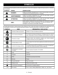
6 − Français Certains des symboles ci-dessous peuvent être utilisés sur l’outil. Veiller à les étudier et à apprendre leur signification. Une interprétation correcte de ces symboles permettra d’utiliser l’outil plus efficacement et de réduire les risques. SYMBOLE NOM DÉSIGNATION / EXPLICATION Symbol...
Page 40 - GLOSSAIRE
7 − Français GLOSSAIRE Trou pilote (perceuses à colonne et scie à découper) Petit trou pratiqué dans une pièce servant de guide pour assurer la précision d’un trou de plus grand diamètre ou pour l’insertion d’une lame de scie à découper. Blocs poussoirs (pour dégauchisseuses/raboteuses) Dispositifs ...
Page 41 - CARACTÉRISTIQUES; FICHE TECHNIQUE
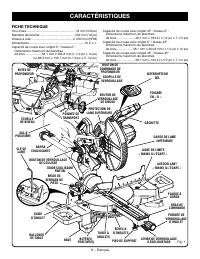
8 − Français CARACTÉRISTIQUES FICHE TECHNIQUE Trou d’axe ......................................................... 16 mm (5/8 po)Diamètre de la lame......................................... 254 mm (10 po)Vitesse à vide ................................................4 100 / min (RPM)Alimentation.......
Page 42 - BOUTON DE VERROUILLAGE DE BISEAU; MANETTE D’ENJAMBEMENT
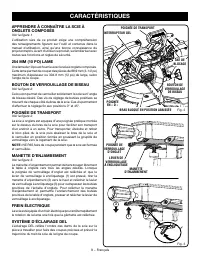
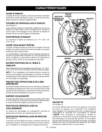
9 − Français 1 3 2 CARACTÉRISTIQUES APPRENDRE À CONNAÎTRE LA SCIE À ONGLETS COMPOSÉS Voir la figure 1. L’utilisation sûre de ce produit exige une compréhension des renseignements figurant sur l’outil et contenus dans le manuel d’utilisation, ainsi qu’une bonne connaissance du projet entrepris. Avant...
Page 44 - LISTE DES PIÈCES DÉTACHÉES; OUTILS NÉCESSAIRES
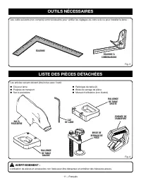
11 − Français LISTE DES PIÈCES DÉTACHÉES Fig. 6 Rallonges de table (2) Bride de serrage de pièce Manuel d’utilisation (non illustré) Clé pour lame Poignée de transport Sac à pouissière Les articles suivant doivent être inclus avec l’outil: AVERTISSEMENT : L’utilisation de pièces et acces...
Page 45 - DÉBALLAGE; ASSEMBLAGE
12 − Français DÉBALLAGE This product requires assembly. Sortir soigneusement la scie du carton en la tenant par la poignée de transport et la base de la scie, et la poser sur un plan de travail horizontal. AVERTISSEMENT : Ne pas utiliser le produit si, en le déballant, vous constatez que des éléme...
Page 46 - TROUS DE FIXATION
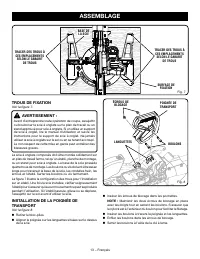
13 − Français Fig. 7 TROUS DE FIXATION Voir la figure 7. AVERTISSEMENT : Avant d’entreprendre toute opération de coupe, assujettir ou boulonner la scie à onglets sur le plan de travail ou un stand approuvé pour scie à onglets. Si on utilise un support de scie à onglet, lire le manuel d’utilisation e...
Page 47 - UTILISATION DU GUIDE DE PROFONDEUR
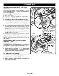
14 − Français UTILISATION DU GUIDE DE PROFONDEUR Voir la figure 9. Lorsqu’il est utilisé, le guide de profondeur limite la course vers le bas de la lame lors de la coupe de rainures et d’autres coupes non traversantes. Pour utiliser le guide de profondeur : Retirer le bloc-piles. Si la scie est ...
Page 49 - RALLONGES DE TABLE
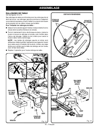
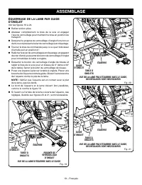
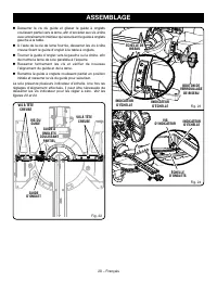
16 − Français ASSEMBLAGE RALLONGES DE TABLE Voir les figures 13 à 15. Des rallonges de table sont fournies pour les côtés gauche et droit de la scie. Les rallonges gauche et droite ne s’adaptent correctement que dans un sens. Veiller à ce que le bord avant de la poignée soit au même niveau que la ta...
Page 50 - INSTALLATION / REMPLACEMENT DE LA LAME
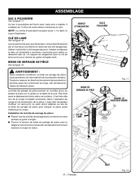
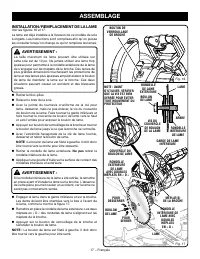
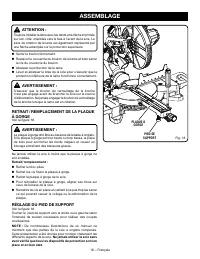
17 − Français POUR SERRER NOTE : AVANT D’UTILISER, VÉRIFIER QUE LA VIS EST BIEN SERRÉE POUR ÉVITER TOUT MOUVEMENT DU PROTECTEUR LAME BOULON DE LAME RONDELLE DE LAME EXTÉRIEURE VIS DU COUVERCLE DE BOULON DE LA LAME ASSEMBLAGE INSTALLATION / REMPLACEMENT DE LA LAME Voir les figures 16 et 17. La lame e...
Page 51 - RÉGLAGE DU PIED DE SUPPORT; PLAQUE À
18 − Français ASSEMBLAGE ATTENTION : Toujours installer la lame avec les dents et la flèche imprimée sur son côté, orientées vers le bas à l’avant de la scie. Le sens de rotation de la lame est également représenté par une flèche estampée sur la protection supérieure. Serrer le boulon fermement. ...
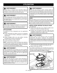
Page 55 - UTILISATION; LOGEMENT DE
22 − Français Fig. 28 AVERTISSEMENT : Pour éviter des blessures graves, toujours garder les mains hors de la zone dangereuse, c’est-à-dire à au moins 100 mm (4 po) de la lame. Ne jamais effectuer de coupes à main levée (c.-à-d. sans maintenir la pièce contre le guide). La lame pourrait se coincer da...
Page 56 - SYSTÈME D’ÉCLAIRAGE DEL; INTERRUPTEUR
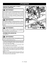
23 − Français TRAVAUX DE COUPE AVEC LA SCIE À ONGLETS COMPOSÉS AVERTISSEMENT : Si un serre-joint ou une bride de serrage de pièce est utilisé pour maintenir la pièce, il ne doit être placé que d’un côté de la lame. La pièce doit être libre d’un côté de la lame afin qu’elle ne risque pas de la bloque...
Page 58 - COUPE EN BISEAU
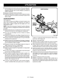
25 − Français Fig. 32 UTILISATION Saisir fermement le manche de la scie. Enfoncer le dispositif de verrouillage avec le po puis serrer la gâchette. Attendre quelques secondes que la lame atteigne sa vitesse de rotation maximale. Abaisser lentement la lame sur la pièce. Relâcher la gâchette et ...
Page 59 - COUPE D’ONGLET COMPOSÉ
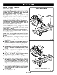
26 − Français Fig. 34 Fig. 33 UTILISATION COUPE D’ONGLET COMPOSÉ Voir les figures 33 et 34. Une coupe d’onglet composé consiste à utiliser un angle d’onglet et un angle de biseau simultanément. Ce type de coupe est utilisé pour la réalisation de cadres, de boîtes à pans inclinés et certains travaux ...
Page 60 - SUPPORT DE PIÈCES LONGUES
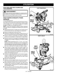
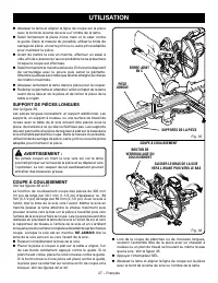
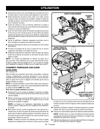
27 − Français Fig. 35 Fig. 36 UTILISATION Abaisser la lame et aligner la ligne de coupe sur la pièce avec le bord de la lame de scie ou l’ombre de la lame. Saisir fermement la pièce d’une main et la caler contre le guide. Dans la mesure du possible, utiliser la bride de serrage de pièce, un serr...
Page 62 - COUPE D’ONGLETS COMPOSÉS; ANGLE
29 − Français UTILISATION COUPE D’ONGLETS COMPOSÉS Le tableau des réglages d’angles ci-dessous est conçu pour faciliter les réglages. Les coupes composées étant les plus difficiles à réaliser, des essais doivent être effectués sur des chutes et la coupe définitive ne doit être effectuée qu’après mûr...
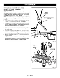
Page 63 - COUPE DE MOULURE COURONNÉE
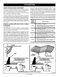
30 − Français Fig. 39 UTILISATION Lors de la coupe d’une moulure couronnée à l’aide de cette méthode, l’angle de biseau doit être réglé à 33,85°. L’angle d’onglet doit être réglé à 31,6° à droite ou à gauche, suivant le sens de coupe nécessaire pour l’application. Consulter le tableau ci-dessous pou...
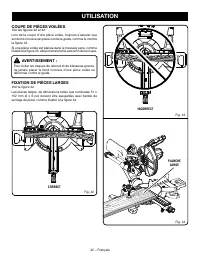
Page 65 - COUPE DE PIÈCES VOILÉES; CORRECT
32 − Français UTILISATION COUPE DE PIÈCES VOILÉES Voir les figures 42 et 43. Lors de la coupe d’une pièce voilée, toujours s’assurer que son bord convexe est placé contre le guide, comme le montre la figure 42. Si une pièce voilée est placée dans le mauvais sens, comme illustré à la figure 43, elle ...
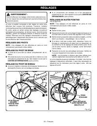
Page 66 - RÉGLAGE DU PIVOT DE BISEAU; RÉGLAGES; RÉGLAGES DE BUTÉE POSITIVE
33 − Français AVERTISSEMENT : Avant d’effectuer tout réglage, retirer le bloc-piles de la scie. Le non respect de cet avertissement pourrait entraîner des blessures graves. La scie à onglets composés a été réglée en usine pour effectuer des coupes très précises. Toutefois, certains composants peuven...
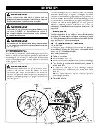
Page 67 - ENTRETIEN; LENTILLE
34 − Français AVERTISSEMENT : Utiliser exclusivement des pièces d’origine pour les réparations. L’usage de toute autre pièce pourrait créer une situation dangereuse ou endommager le produit. AVERTISSEMENT : Toujours porter une protection oculaire certifiée conforme à la norme ANSI Z87.1 lors de l’ut...
Page 68 - REGLAS DE SEGURIDAD GENERALES; ÁREA DE TRABAJO
2 − Español REGLAS DE SEGURIDAD GENERALES ADVERTENCIA: Lea todas las advertencias, instrucciones, ilustraciones y especificaciones proporcionadas con esta herramienta eléctrica. No seguir las instrucciones indicadas a continuación puede provocar descargas eléctricas, incendios o lesiones graves. Gua...
Page 69 - SERVICIO
3 − Español REGLAS DE SEGURIDAD GENERALES REGLAS DE SEGURIDAD SIERRA INGLETEADORA piezas móviles, ruptura de piezas o toda otra condición que pueda afectar el funcionamiento de la herramienta eléctrica. Si está dañada la herramienta eléctrica, permita que la reparen antes de usarla. Numerosos accide...
Page 70 - REGLAS DE SEGURIDAD SIERRA INGLETEADORA
4 − Español REGLAS DE SEGURIDAD SIERRA INGLETEADORA Utilice abrazaderas para sostener la pieza de trabajo cuando sea posible. Si sostendrá la pieza de trabajo con la mano, siempre manténgala a una distancia de, al menos, 100 mm en ambos lados de la hoja de la sierra. No use esta sierra para cortar...
Page 71 - ADVERTENCIAS DE SEGURIDAD ADICIONALES
5 − Español ADVERTENCIAS DE SEGURIDAD ADICIONALES Inspeccione periódicamente los cordones eléctricos de las herramientas. Si están dañados, llévelos a un establecimiento de servicio autorizado para que los revise un técnico de servicio calificado. Repare o reemplace de inmediato todo cordón dañado...
Page 72 - SÍMBOLOS; SÍMBOLO
6 − Español Es posible que se empleen en esta herramienta algunos de los siguientes símbolos. Le suplicamos estudiarlos y aprender su significado. Una correcta interpretación de estos símbolos le permitirá utilizar mejor y de manera más segura la herramienta. SÍMBOLO NOMBRE DENOMINACIÓN/EXPLICACIÓN ...
Page 73 - GLOSARIO DE TÉRMINOS
7 − Español GLOSARIO DE TÉRMINOS Agujero guía (taladradoras de columna y sierras caladoras) Es un agujero pequeño taladrado en una pieza de trabajo, el cual sirve como guía para taladrar con precisión agujeros más grandes o para la colocación de la hoja de la sierra caladora. Bloques empujadores (pa...
Page 74 - CARACTERÍSTICAS; ESPECIFICACIONES DEL PRODUCTO
8 − Español CARACTERÍSTICAS ESPECIFICACIONES DEL PRODUCTO Orificio del eje .....................................................16 mm (5/8 pulg.)Diámetro de la hoja ........................................... 254 mm (10 pulg.)Velocidad en vacío .............................................. 4 100/mi...
Page 76 - ESCALA DE INGLETES; CANDADO
10 − Español Fig. 4 CARACTERÍSTICAS MANIJA DE FIJACIÓN DE INGLETE Vea la figura 3. La manija de fijación de inglete asegura firmemente la sierra en los ángulos de inglete deseados. Ajuste el mango para fijar la sierra en su lugar. Para liberar la sierra, afloje el mango y apriete la palanca de deten...
Page 77 - LISTA DE PIEZAS SUELTAS; HERRAMIENTAS NECESARIAS
11 − Español LISTA DE PIEZAS SUELTAS Fig. 6 Prensa de trabajo Manual del operador (no se muestra) Llave de hoja Saco captapolvo Extensiones de la mesa (2) Vienen incluidos los siguientes artículos con la herramienta: ADVERTENCIA: El empleo de aditamentos o accesorios no enumerados arriba p...
Page 78 - ARMADO; DESEMPAQUETADO
12 − Español ARMADO DESEMPAQUETADO Este producto requiere armarse. Levante cuidadosamente de la caja la sierra sujetándola del mango de acarreo y de la base, y colóquela sobre una superficie de trabajo a nivel. ADVERTENCIA: No utilice este producto si alguna pieza incluida en la Lista de piezas su...
Page 79 - AGUJEROS DE MONTAJE; SAW BASE
13 − Español SEÑALE EL CENTRO DE LOS AGUJEROS EN ESTOS LUGARES SEÑALE EL CENTRO DE LOS AGUJEROS EN ESTOS LUGARES SUPERFICIE DE MONTAJE AGUJEROS DE MONTAJE Vea la figura 7. ADVERTENCIA: Antes de iniciar cualquier operación de corte, sujete con prensa(s) o atornille la sierra ingleteadora al banco de ...
Page 80 - USO EL TOPE DE PROFUNDIDAD
14 − Español Fig. 10 Fig. 9 ARMADO USO EL TOPE DE PROFUNDIDAD Vea la figura 9. Su uso limita el descenso de la hoja durante cortes de ranura y demás tipos de corte no pasante. Para usar el tope de profundidad: Desconecte la sierra Si la sierra está en posición de almacenamiento o transporte, des...
Page 81 - SACO CAPTAPOLVO; LLAVE DE LA HOJA
15 − Español ARMADO SACO CAPTAPOLVO Vea la figura 11. Se suministra un saco captapolvo para utilizarse con la sierra ingleteadora. Se acopla en la abertura de salida del aserrín, en la parte posterior de la sierra. NOTA: El orificio de escape acepta también 1-1/4 en. saco captapolvo. LLAVE DE LA HOJ...
Page 82 - EXTENSIONES DE LA MESA
16 − Español Fig. 13 BOLSILLO DE TUERCA PERNO TUERCA DE BLOQUEO BASE PERNO BASE Fig. 14 Fig. 15 ORIFICIO DE PERNO EXTENSIONES DE LA MESA Vea las figuras 13 a 15. Se proporcionan extensiones de la mesa para los lados izquierdo y derecho de la sierra. Las extensiones del lado izquierdo y derecho solo ...
Page 83 - PARA INSTALAR O REEMPLAZAR LA HOJA
17 − Español PERNO DE LA HOJA PARA AFLOJAR PARA APRETAR HOJA ARANDELA INTERIOR DE LA HOJA CON DOS PARTES PLANAS EN “D” Fig. 16 Fig. 17 PARA INSTALAR O REEMPLAZAR LA HOJA Vea las figuras 16 y 17. La hoja viene instalada en este modelo de sierra ingleteadora. Para su referencia, se incluyen instruccio...
Page 85 - ESCUADRADO DE LA HOJA CON LA MESA
19 − Español MANIJA DE FIJACIÓN DE INGLETE MESA DE INGLETES VISTA A DE LA HOJA A ESCUADRA CON LA GUÍA ESCUADRA GUÍA DE INGLETES ARMADO ESCUADRADO DE LA HOJA CON LA MESA DE INGLETES Vea las figuras 19 a 24. Retire el paquete de pilas. Tire del brazo de la sierra completamente hacia abajo y enganc...
Page 88 - FUNCIONAMIENTO
22 − Español Fig. 28 ADVERTENCIA: No permita que su familarización con las herramientas lo vuelva descuidado. Tenga presente que un descuido de un instante es suficiente para causar una lesión grave. ADVERTENCIA: Siempre póngase protección ocular con la marca de cumplimiento de la norma ANSI Z87.1. ...
Page 89 - SISTEMA DE ILUMINACIÓN LED
23 − Español SOMBRA DEL DIENTE DE LA HOJA PROYECTADA EN LA PIEZA DE TRABAJO Fig. 29 FUNCIONAMIENTO PROCEDIMIENTO DE CORTE CON LA SIERRA INGLETEADORA COMPUESTA ADVERTENCIA: Al usar la prensa de trabajo, prensa en c, u otra prensa adecuada para asegurar la pieza, sujete ésta sólo en un lado de la hoja...
Page 90 - PARA REALIZAR CORTES NO DESLIZANTES
24 − Español FUNCIONAMIENTO PARA REALIZAR CORTES NO DESLIZANTES ADVERTENCIA: Apriete firmemente la perilla de fijación de la guía telescópica para realizar cortes no deslizantes. Si no se aprieta esta perilla, podría moverse el cabezal de la sierra durante la tarea de corte. PARA REALIZAR CORTES DE ...
Page 91 - PARA CORTAR A BISEL
25 − Español varios segundos para que la hoja alcance su velocidad máxima. Baje lentamente la hoja de la sierra haciendo que se introduzca y traspase la pieza de trabajo. Suelte el gatillo del interruptor y espere a que la hoja de la sierra deje de girar antes de levantarla de la pieza de trabaj...
Page 94 - FORMA DE HACER UNA GUÍA AUXILIAR
28 − Español Fig. 37 Fig. 38 Con la sierra apagada, sujete firmemente el mango de la sierra y tire de ella hacia delante hasta que el eje de la hoja (centro de la hoja de la sierra) haya sobrepasado la parte delantera de la pieza de trabajo o hasta que la sierra esté completamente extendida. Opr...
Page 95 - CÓMO EFECTUAR CORTES A INGLETE COMBINADOS; INCLINACIÓN
29 − Español CÓMO EFECTUAR CORTES A INGLETE COMBINADOS Como ayuda para realizar los ajustes correctos, se suministra la siguiente tabla de ángulos combinados. Puesto que los cortes combinados son los más difíciles de obtener, deben efectuarse cortes de prueba en material de desecho, así como una gra...
Page 96 - CÓMO CORTAR MOLDURAS DE CORONA
30 − Español Al cortar molduras de corona con este método, el ángulo de bisel debe fijarse a 33,85°. El ángulo de inglete debe fijarse a 31,6°, a la derecha o izquierda, según el corte deseado para cada aplicación en particular. En la tabla mostrada a continuación encontrará los ajustes correctos de...
Page 97 - CANTO INFERIOR
31 − Español Fig. 41 Fig. 40 ENCAJE DE MOLDURA EN CORONA CONTRA LA GUÍA DE INGLETE Vea las figuras 40 y 41. NOTA: Este método de corte es para las molduras de corona de entre 117,5 mm (4-5/8 pulg.) y 133,3 mm (5-1/4 pulg.) de altura. No intente cortar una moldura de más de 133,3 mm (5-1/4 pulg.) de ...
Page 98 - CÓMO CORTAR MATERIAL DISTORSIONADO
32 − Español Fig. 42 Fig. 43 Fig. 44 FORMA INCORRECTA CÓMO CORTAR MATERIAL DISTORSIONADO Vea las figuras 42 y 43. Al cortar material distorsionado, siempre asegúrese de que esté colocado en la mesa de ingletes con el lado convexo contra la guía, como se muestra en la figura 42. Si se coloca de una f...
Page 99 - AJUSTES; AJUSTES DE LOS PIVOTES; AJUSTE DEL PIVOTE DE BISEL; AJUSTE DE LOS TOPES
33 − Español Fig. 45 AJUSTES ADVERTENCIA: Antes de efectuar cualquier ajuste, quite el paquete de baterías de la sierra. La inobservancia de esta advertencia podría causar lesiones corporales serias. La sierra ingleteadora combinada ha sido ajustada en la fábrica para producir cortes muy exactos. No...
Page 100 - MANTENIMIENTO GENERAL; MANTENIMIENTO; LUBRICACIÓN
34 − Español ADVERTENCIA: Al dar servicio a la unidad, utilice sólo piezas de repuesto idénticas. El empleo de piezas diferentes puede presentar un peligro o causar daños al producto. ADVERTENCIA: Siempre póngase protección ocular con la marca de cumplimiento de la norma ANSI Z87.1. Si la operación ...
Page 104 - OPERATOR’S MANUAL; MANUEL D’UTILISATION / MANUAL DEL OPERADOR; 0 in. 18V SLIDING COMPOUND MITER SAW WITH LED
TTI CONSUMER POWER TOOLS, INC. P.O. Box 1288, Anderson, SC 29622 • Phone 1-800-525-2579 États-Unis, Téléphone 1-800-525-2579 • USA, Teléfono 1-800-525-2579 www.ryobitools.com RYOBI is a trademark of Ryobi Limited and is used pursuant to a license granted by Ryobi Limited. RYOBI est une marque de Ryo...