Page 2 - READ ALL INSTRUCTIONS; GENERAL SAFETY RULES
2 − English WARNING: Read all safety warnings and all instructions. Failure to follow the warnings and instructions may result in electric shock, fire and/or serious injury. READ ALL INSTRUCTIONS KNOW YOUR POWER TOOL. Read the operator’s manual carefully. Learn the applications and limitations as ...
Page 3 - WHEN SERVICING
3 − English GENERAL SAFETY RULES NEVER START A TOOL WHEN ANY ROTATING COM-PONENT IS IN CONTACT WITH THE WORKPIECE. DO NOT OPERATE A TOOL WHILE UNDER THE IN-FLUENCE OF DRUGS, ALCOHOL, OR ANY MEDICA-TION. WHEN SERVICING use only identical replacement parts. Use of any other parts may create a ha...
Page 4 - SPECIFIC SAFETY RULES
4 − English SPECIFIC SAFETY RULES FIRMLY CLAMP OR BOLT the tool to a workbench or table at approximately hip height. KEEP HANDS AWAY FROM CUTTING AREA. Do not reach underneath work or in blade cutting path with hands and fingers for any reason. Always turn the power off. ALWAYS SUPPORT LONG WO...
Page 5 - SYMBOLS; CALIFORNIA PROPOSITION 65
5 − English SYMBOLS Some of the following symbols may be used on this tool. Please study them and learn their meaning. Proper interpretation of these symbols will allow you to operate the tool better and safer. SYMBOL NAME DESIGNATION/EXPLANATION Safety Alert Indicates a potential personal injury ha...
Page 6 - GLOSSARY OF TERMS
6 − English GLOSSARY OF TERMS Push Blocks (for jointer planers) Device used to feed the workpiece over the jointer planer cutterhead during any operation. This aid helps keep the operator’s hands well away from the cutterhead. Push Blocks (for table saws) Device used to hold the workpiece during cut...
Page 7 - FEATURES; PRODUCT SPECIFICATIONS
7 − English FEATURES PRODUCT SPECIFICATIONS Arbor Hole .................................................................5/8 in.Blade Diameter ........................................................... 10 in.No Load Speed .....................................4,000 r/min. (RPM)Motor ....................
Page 8 - ̊ BEVEL STOP PIN
8 − English FEATURES KNOW YOUR COMPOUND MITER SAW See Figure 1. The safe use of this product requires an understanding of the information on the tool and in this operator’s manual as well as a knowledge of the project you are attempting. Before use of this product, familiarize yourself with all oper...
Page 10 - LOOSE PARTS LIST; TOOLS NEEDED
10 − English LOOSE PARTS LIST Fig. 6 Work Clamp Operator’s Manual Dust Bag Sliding Miter Fence WORK CLAMP DUST BAG SLIDING MITER FENCE The following items are included with the tool: WARNING: The use of attachments or accessories not listed might be hazardous and could cause serious personal...
Page 11 - ASSEMBLY; UNPACKING
11 − English ASSEMBLY UNPACKING This product requires assembly. Carefully lift saw from the carton by the carrying handle and the saw base, and place it on a level work surface. WARNING: Do not use this product if any parts on the Loose Parts List are already assembled to your product when you unp...
Page 12 - MOUNTING HOLES; To unlock and raise the saw arm:; DUST BAG
12 − English Fig. 8 ASSEMBLY MOUNTING HOLES See Figure 7. WARNING: Before starting any cutting operation, clamp or bolt your miter saw to a workbench or an approved miter saw stand. If a miter saw stand is used, read operator’s manual and follow the instructions for the miter saw stand. Never operat...
Page 13 - INSTALLING SLIDING MITER FENCE; BLADE WRENCH; To install the work clamp:
13 − English ASSEMBLY INSTALLING SLIDING MITER FENCE See Figure 10. Turn the fence lock knob counterclockwise, to clear fence slots. Install the sliding miter fence. Lower fence into fence slot. Be sure side of fence lines up flush with side of fixed fence. Tighten fence lock knob securely. BL...
Page 14 - TO INSTALL/REPLACE THE BLADE
14 − English ASSEMBLY TO INSTALL/REPLACE THE BLADE See Figures 12 - 13. WARNING: A 10 in. blade is the maximum blade capacity of the saw. Never use a blade that is too thick to allow outer blade washer to engage with the flats on the spindle. Larger blades will come in contact with the blade guards,...
Page 15 - REMOVING/REPLACING THE THROAT PLATE
15 − English ASSEMBLY REMOVING/REPLACING THE THROAT PLATE See Figure 14. WARNING: The throat plate must be below the miter table. If the throat plate is too high or too low, the workpiece can catch on the uneven edges resulting in binding which could result in serious personal injury. Never operate ...
Page 16 - BEVEL
16 − English ASSEMBLY Loosen the fence lock knob and lift to remove the sliding fence from the miter fence. Using the blade wrench provided, loosen the socket head screws that secure the fixed miter fence to the base. Rotate the fixed miter fence left or right until the saw blade is parallel w...
Page 17 - SQUARING THE BLADE TO THE MITER TABLE
17 − English ASSEMBLY SQUARING THE BLADE TO THE MITER TABLE See Figures 22 - 24. Remove the battery packs from the tool. Pull the saw arm all the way down and engage the lock pin to hold the saw arm in transport position. Loosen the miter lock knob approximately one-half turn and squeeze the d...
Page 18 - RED; ALIGNING THE LASER GUIDE LINE
18 − English ASSEMBLY Fig. 25 RED LINE LASER GUIDE BUTTON LASER RADIATION AVOID DIRECT EYE EXPOSURE CLASS IIIa LASER PRODUCT MAXIMUM OUTPUT: <5mW WAVELENGTH: 635-660nm • To reduce the risk of injury, user must read and understand the operator’s manual before using the miter saw. • Wear eye protec...
Page 19 - OPERATION; APPLICATIONS; BATTERY
19 − English OPERATION WARNING: Do not allow familiarity with tools to make you careless. Remember that a careless fraction of a second is sufficient to inflict serious injury. WARNING: Always wear eye protection with side shields marked to comply with ANSI Z87.1. Failure to do so could result in ob...
Page 20 - MITER CUT; CROSS CUT
20 − English CUTTING WITH YOUR COMPOUND MITER SAW WARNING: When using a work clamp or C-clamp to secure your workpiece, clamp workpiece on one side of the blade only. The workpiece must remain free on one side of the blade to prevent the blade from binding in workpiece. The workpiece binding the bla...
Page 21 - TO BEVEL CUT
21 − English OPERATION the convex side against the fence. If the concave edge of a board is placed against the fence, the board could collapse on the blade at the end of the cut, jamming the blade. See Figures 39 - 40. When cutting long pieces of lumber or molding, support the opposite end of the ...
Page 22 - TO COMPOUND MITER CUT; COMPOUND MITER CUT
22 − English OPERATION TO COMPOUND MITER CUT See Figures 30 - 31. A compound miter cut is a cut made using a miter angle and a bevel angle at the same time. This type of cut is used to make picture frames, cut molding, make boxes with sloping sides, and for certain roof framing cuts. To make this ty...
Page 23 - TO SLIDE CUT; NEVER
23 − English OPERATION Slide the saw head to its most rearward position and tighten the slide lock knob securely. Align cutting line on the workpiece with the edge of saw blade or laser line. Grasp the stock firmly with one hand and secure it against the fence. Use the optional work clamp or a...
Page 24 - TO SUPPORT LONG WORKPIECES; MUST
24 − English OPERATION Release the switch trigger and wait until the electric brake stops the blade from turning before raising the blade out of workpiece and removing the workpiece from the miter table. NOTE: A cross cut is made by cutting across the grain of the workpiece. A straight cross cut i...
Page 25 - PITCH; CUTTING COMPOUND MITERS
25 − English OPERATION 4 PITCH OF SIDE NUMBER OF SIDES 0° 6 M- 45.00°B- 0.00° 5° 10° 15° 20° 25° 30° 35° 40° 45° 50° 55° 60° 65° 70° 75° 80° 85° 90° 5 7 8 9 10 M- 36.00°B- 0.00° M- 30.00°B- 0.00° M- 25.71°B- 0.00° M- 22.50°B- 0.00° M- 20.00°B- 0.00° M- 18.00°B- 0.00° Each B (Bevel) and M (Miter) Set...
Page 26 - CUTTING CROWN MOLDING; Bevel
26 − English OPERATION Fig. 36 When cutting crown molding by this method, the bevel angle should be set at 33.85 ° . The miter angle should be set at 31.6 ° either right or left, depending on the desired cut for the application. See the chart below for correct angle settings and correct positioning ...
Page 28 - CUTTING WARPED MATERIAL; RIGHT
28 − English OPERATION CUTTING WARPED MATERIAL See Figures 39 - 40. When cutting warped material, always make sure it is positioned on the miter table with the convex side against the fence as shown in Figure 39. If the warped material is positioned the wrong way as shown in Figure 40, it will pinch...
Page 29 - OPTIONAL TABLE EXTENSIONS; To install table extensions:
29 − English OPERATION Fig. 42 TABLE EXTENSION BASE OPTIONAL TABLE EXTENSIONS See Figures 42 - 44. You may purchase table extensions, part no. 089041038723, for use with the saw. Table extensions fit into the holes on both the left and the right sides of the saw. To install table extensions: Remov...
Page 30 - ADJUSTMENTS; PIVOT ADJUSTMENTS; AUTHORIZED SERVICE CENTER.; TO ADJUST THE BEVEL PIVOT; AUTHORIZED SERVICE; POSITIVE STOP ADJUSTMENTS
30 − English POSITIVE STOP ADJUSTMENT SCREW FOR 45 ° RIGHT ANGLE ADJUSTMENTS WARNING: Before performing any adjustment, make sure the tool is unplugged from the power supply. Failure to heed this warning could result in serious personal injury. The compound miter saw has been adjusted at the factory...
Page 31 - TO ADJUST THE LASER GUIDE; AUTHORIZED SERVICE CENTER
31 − English ADJUSTMENTS DANGER: Laser radiation. Avoid direct eye contact with light source. WARNING: Use of controls or adjustments or performance of procedures other than those specified herein can result in hazardous radiation exposure. TO ADJUST THE LASER GUIDE See Figure 46. Set miter and be...
Page 32 - MAINTENANCE; GENERAL MAINTENANCE
32 − English MAINTENANCE WARNING: When servicing, use only identical replacement parts. Use of any other part can create a hazard or cause product damage. WARNING: Always wear eye protection with side shields marked to comply with ANSI Z87.1 during product operation. If operation is dusty, also wear...
Page 33 - LIRE TOUTES LES INSTRUCTIONS; RÈGLES DE SÉCURITÉ GÉNÉRALES
2 − Français AVERTISSEMENT : Lire attentivement toutes les instructions. Le non respect de toutes les instructions ci-dessous peut entraîner un choc électrique, un incendie et/ou des blessures graves. LIRE TOUTES LES INSTRUCTIONS V E I L L E R À B I E N C O N N A Î T R E L ’ O U T I L . L i r e at...
Page 34 - LÉE EN POSITION D’ARRÊT AVANT D’INSÉRER LES; RÈGLES DE SÉCURITÉ PARTICULIÈRES
3 − Français RÈGLES DE SÉCURITÉ GÉNÉRALES NE PAS UTILISER L’OUTIL SI LE COMMUTATEUR NE PERMET PAS DE LE METTRE EN MARCHE OU DE L’ARRÊTER. Faire remplacer les commutateurs défectueux dans un centre de réparations agréé. N’UTILISER QUE LES LAMES APPROPRIÉES. Ne pas utiliser de lames dont le trou n...
Page 35 - DE LA POSITION MARCHE À LA POSITION ARRÊT
4 − Français RÈGLES DE SÉCURITÉ PARTICULIÈRES CETTE SCIE EST UNIQUEMENT CONÇUE POUR COUPER DU BOIS, DES DÉRIVÉS DU BOIS ET CERTAINS PLASTIQUES. NE PAS COUPER DE M É T A U X , C É R A M I Q U E S O U P R O D U I T S D E MAÇONNERIE. NE JAMAIS UTILISER DE BUTÉE RÉGLABLE SUR L’EXTRÉMITÉ CHUTE D’UNE ...
Page 36 - SYMBOLES; PROPOSITION 65 DE L’ÉTAT DE CALIFORNIE
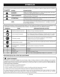
5 − Français Certains des symboles ci-dessous peuvent être utilisés sur l’outil. Veiller à les étudier et à apprendre leur signification. Une interprétation correcte de ces symboles permettra d’utiliser l’outil plus efficacement et de réduire les risques. SYMBOLE NOM DÉSIGNATION/EXPLICATION Symbole ...
Page 37 - GLOSSAIRE
6 − Français GLOSSAIRE Blocs poussoirs (pour dégauchisseuses/raboteuses) Dispositif utilisés pour pousser le matériau contre la tête de coupe lors de toute opération. Ce dispositif aide à tenir la main de l’opérateur bien à l’écart de la lame. Blocs poussoirs (pour scies à table) Dispositifs utilisé...
Page 38 - CARACTÉRISTIQUES; FICHE TECHNIQUE; CLÉ DE
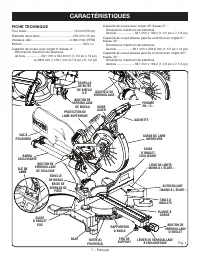
7 − Français CARACTÉRISTIQUES FICHE TECHNIQUE Trou d’axe .......................................................16 mm (5/8 po)Diamètre de la lame....................................... 254 mm (10 po)Vitesse à vide ............................................ 4 000 r/min (RPM)Moteur ....................
Page 39 - BUTÉE DE BISEAU À 0 ̊
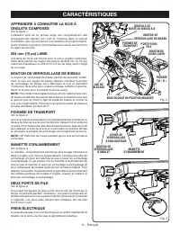
8 − Français CARACTÉRISTIQUES APPRENDRE À CONNAÎTRE LA SCIE À ONGLETS COMPOSÉS Voir la figure 1. L’utilisation sûre de ce produit exige une compréhension des renseignements figurant sur l’outil et contenus dans le manuel d’utilisation, ainsi qu’une bonne connaissance du projet entrepris. Avant d’uti...
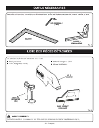
Page 41 - LISTE DES PIÈCES DÉTACHÉES; OUTILS NÉCESSAIRES
10 − Français LISTE DES PIÈCES DÉTACHÉES Fig. 6 Bride de serrage de pièce Manuel d’utilisation Sac à pouissière Guide d’onglet coulissant Les articles suivant doivent être inclus avec l’outil: AVERTISSEMENT : L’utilisation de pièces et accessoires non listés peut être dangereux et entraîner ...
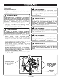
Page 42 - ASSEMBLAGE; DÉBALLAGE
11 − Français ASSEMBLAGE DÉBALLAGE Ce produit doit être assemblé. Sortir soigneusement la scie du carton en la tenant par la poignée de transport et la base de la scie, et la poser sur un plan de travail horizontal. AVERTISSEMENT : Ne pas utiliser le produit si, en le déballant, vous constatez que...
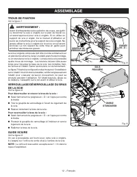
Page 43 - TROUS DE FIXATION; Pour déverrouiller et relever le bras de la scie :; GUIDE SCIURE
12 − Français ASSEMBLAGE TROUS DE FIXATION Voir la figure 7. AVERTISSEMENT : Avant d’entreprendre toute opération de coupe, assujettir ou boulonner la scie à onglets sur le plan de travail ou un stand approuvé pour scie à onglets. Si on utilise un support de scie à onglet, lire le manuel d’utilisati...
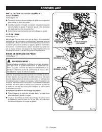
Page 44 - CLÉ DE LAME; Installation de la bride de serrage de pièce :
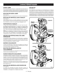
13 − Français ASSEMBLAGE INSTALLATION DU GUIDE D’ONGLET COULISSANT Voir la figure 10. Tourner le bouton de verrouillage du guide vers la gauche pour libérer la fente du guide. Installer le guide d’onglet coulissant. Abaisser le guide dans la fente du guide. S’assurer que le côté du guide est éga...
Page 45 - INSTALLATION/REMPLACEMENT DE LA LAME
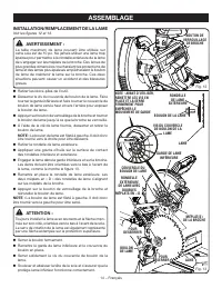
14 − Français ASSEMBLAGE INSTALLATION/REMPLACEMENT DE LA LAME Voir les figures 12 et 13. AVERTISSEMENT : La taille maximum de lame pouvant être utilisée sur cette scie est de 10 po. Ne jamais utiliser une lame trop épaisse pour permettre à la rondelle extérieure de la lame de s’engager sur les mépla...
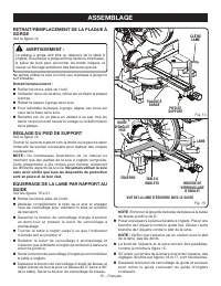
Page 46 - RÉGLAGE DU PIED DE SUPPORT; Ne jamais utiliser la scie
15 − Français ASSEMBLAGE RETRAIT/REMPLACEMENT DE LA PLAQUE À GORGE Voir la figure 14. AVERTISSEMENT : La plaque à gorge doit être au dessous de la table à onglets. Si la plaque à gorge est trop haute ou trop basse, la pièce de bois peut accrocher les bords inégaux et causer un blocage entraînant des...
Page 47 - BISEAU À 0 ̊
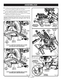
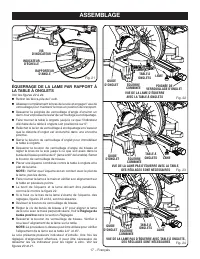
16 − Français ASSEMBLAGE À l’aide de la clé de lame fournie, desserrer les vis à tête creuse fixant le guide d’onglet fixe à la base. Tourner le guide d’onglet fixe vers la gauche ou la droite, afin de mettre la lame de scie parallèle à l’équerre. Resserrer fermement les vis et vérifier de nou...
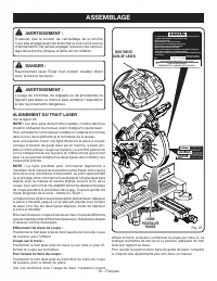
Page 49 - ALIGNEMENT DU TRAIT LASER; LIGNE
18 − Français ASSEMBLAGE AVERTISSEMENT : S’assurer que le bouton de verrouillage de la broche n’est pas engagé avant de brancher la scie sur la source d’alimentation. Ne jamais engager le bouton de verrouil-lage de la broche lorsque la lame est en rotation. DANGER : Rayonnement laser. Éviter tout co...
Page 50 - UTILISATION
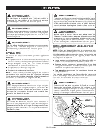
19 − Français UTILISATION AVERTISSEMENT : Ne pas laisser la familiarité avec l’outil faire oublier la prudence. Ne pas oublier qu’une fraction de seconde d’inattention peut entraîner des blessures graves. AVERTISSEMENT : Toujours porter une protection oculaire certifiée conforme à la norme ANSI Z87....
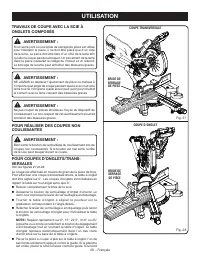
Page 52 - COUPE EN BISEAU; BRIDE DE
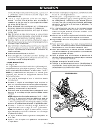
21 − Français UTILISATION concave d’une pièce est placé contre le guide, la pièce peut se refermer sur la lame en fin de coupe et la bloquer. Voir les figures 39 et 40. Lors de la coupe de planches ou de moulures longues, soutenir l’extrémité libre de la pièce avec un chevalet à rouleau ou un plan...
Page 53 - COUPE D’ONGLET COMPOSÉ
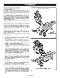
22 − Français UTILISATION COUPE D’ONGLET COMPOSÉ Voir les figures 30 et 31. Une coupe d’onglet composé consiste à utiliser un angle d’onglet et un angle de biseau simultanément. Ce type de coupe est utilisé pour la réalisation de cadres, de boîtes à pans inclinés et certains travaux de charpente. Po...
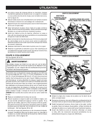
Page 54 - COUPE À COULISSEMENT; NE
23 − Français UTILISATION Lors de la coupe de longues pièces ou moulures, retenez l’extrémité opposée de la pièce avec un support à rouleau ou une surface de travail de niveau avec la table de la scie. Voir la figure 34. Glisser la tête de la scie complètement vers l’arrière et serrer fermement ...
Page 55 - SUPPORT DE PIÈCES LONGUES; DOIT
24 − Français UTILISATION Avec la scie à l’arrêt, saisir fermement la poignée de la scie et tirer la scie vers l’avant jusqu’à ce que la scie soit complètement déployée. Serrer la gâchette. Attendre quelques secondes que la lame atteigne sa vitesse de rotation maximale. Abaisser lentement la l...
Page 56 - ANGLE; COUPE D’ONGLETS COMPOSÉS
25 − Français UTILISATION 4 ANGLE DE CÔTÉ NOMBRE DE CÔTÉS 0° 6 5° 10° 15° 20° 25° 30° 35° 40° 45° 50° 55° 60° 65° 70° 75° 80° 85° 90° 5 7 8 9 10 Chaque angle B (biseau) et M (onglet) est indiquée au 0,005 ème de degré le plus proche. RÉGLAGES D’ANGLES COMPOSÉS POUR LES CONSTRUCTIONS COURANTES COUPE ...
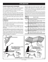
Page 57 - COUPE DE MOULURE COURONNÉE
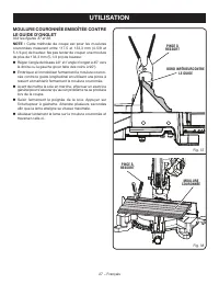
26 − Français UTILISATION Lors de la coupe d’une moulure couronnée à l’aide de cette méthode, l’angle de biseau doit être réglé à 33,85°. L’angle d’onglet doit être réglé à 31,6° à droite ou à gauche, suivant le sens de coupe nécessaire pour l’application. Consulter le tableau ci-dessous pour les ré...
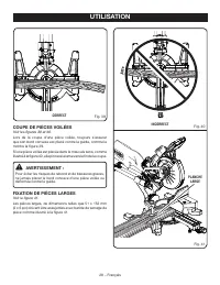
Page 59 - COUPE DE PIÈCES VOILÉES; PLANCHE
28 − Français UTILISATION COUPE DE PIÈCES VOILÉES Voir les figures 39 et 40. Lors de la coupe d’une pièce voilée, toujours s’assurer que son bord convexe est placé contre le guide, comme le montre la figure 39. Si une pièce voilée est placée dans le mauvais sens, comme illustré à la figure 40, elle ...
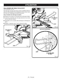
Page 60 - RALLONGES DE TABLE FACULTATIF; Pour l’installer les rallonges de table :; VIS DE RALLONGE
29 − Français UTILISATION RALLONGES DE TABLE FACULTATIF Voir les figures 42 à 44. Des rallonges de table pour la scie, pièce no 089041038723, peuvent être achetées. Des rallonges de table entrent dans les trous à la côtés gauche et droit de la scie. Pour l’installer les rallonges de table : Retire...
Page 61 - RÉGLAGES; RÉGLAGES DES PIVOTS; CENTRE DE RÉPARATIONS; RÉGLAGE DU PIVOT DE BISEAU; CENTRE DE; RÉGLAGES DE BUTÉE POSITIVE
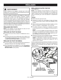
30 − Français VIS DE RÉGLAGE DE BUTÉE POSITIVE POUR ONGLETS À 45° À DROITE RÉGLAGES AVERTISSEMENT : Avant d’effectuer tout réglage, s’assurer que l’outil est débranché. Le non respect de cet avertissement pourrait entraîner des blessures graves. La scie à onglets composés a été réglée en usine pour ...
Page 62 - RÉGLAGE DU LASER
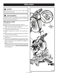
31 − Français RÉGLAGES DANGER : Rayonnement laser. Éviter tout contact oculaire direct avec la source du rayon. AVERTISSEMENT : L’usage de contrôles, de réglages ou de procédures ne figurant pas dans ce manuel peut entraîner l’exposition à des rayonnements dangereux. RÉGLAGE DU LASER Voir la figure ...
Page 63 - ENTRETIEN; ENTRETIEN GÉNÉRAL
32 − Français ENTRETIEN AVERTISSEMENT : Utiliser exclusivement des pièces d’origine pour les réparations. L’usage de toute autre pièce pourrait créer une situation dangereuse ou endommager le produit. AVERTISSEMENT : Toujours porter une protection oculaire certifiée conforme à la norme ANSI Z87.1 lo...
Page 64 - REGLAS DE SEGURIDAD GENERALES; LEA TODAS LAS INSTRUCCIONES
2 − Español REGLAS DE SEGURIDAD GENERALES ADVERTENCIA: Lea y comprenda todas las instrucciones. El incumplimiento de las instrucciones señaladas abajo puede causar descargas eléctricas, incendios y lesiones serias. LEA TODAS LAS INSTRUCCIONES FAMILIARÍCESE CON SU HERRAMIENTA ELÉCTRICA. Lea cuidado...
Page 65 - SUJETE FIRMEMENTE CON PRENSAS DE MANO O
3 − Español REGLAS DE SEGURIDAD GENERALES PERMANEZCA ALERTA Y EN CONTROL. Preste atención a lo que esté haciendo y aplique el sentido común. No utilice la herramienta cuando esté cansado. No se apresure. NO UTILICE LA HERRAMIENTA SI EL INTERRUPTOR NO ENCIENDE O NO APAGA. Lleve todo interruptor d...
Page 66 - REGLAS DE SEGURIDAD ESPECÍFICAS
4 − Español REGLAS DE SEGURIDAD ESPECÍFICAS ASEGÚRESE DE QUE LA HOJA TRASPASE LA PIEZA DE TRABAJO. Nunca arranque la sierra con la hoja tocando la pieza de trabajo. Permita que el motor se detenga completamente antes de iniciar el corte. ASEGÚRESE DE QUE LA MESA DE INGLETES Y EL BRAZO DE LA SIER...
Page 67 - SÍMBOLOS; SÍMBOLO
5 − Español SÍMBOLOS Es posible que se empleen en esta herramienta algunos de los siguientes símbolos. Le suplicamos estudiarlos y aprender su significado. Una correcta interpretación de estos símbolos le permitirá utilizar mejor y de manera más segura la herramienta. SÍMBOLO NOMBRE DENOMINACIÓN/EXP...
Page 68 - GLOSARIO DE TÉRMINOS
6 − Español GLOSARIO DE TÉRMINOS Bloques empujadores (para cepillos de juntas) Son dispositivos empleados para avanzar la pieza de trabajo por el cepillo de juntas durante cualquier operación. Este medio ayuda al operador a mantener las manos alejadas de la cabeza de corte. Bloques empujadores (para...
Page 69 - CARACTERÍSTICAS; ESPECIFICACIONES DEL PRODUCTO; LLAVE
7 − Español CARACTERÍSTICAS ESPECIFICACIONES DEL PRODUCTO Orificio del eje .................................................... 16 mm (5/8 pulg.)Diámetro de la hoja .......................................... 254 mm (10 pulg.)Velocidad en vacío ........................................... 4 000 r/min ...
Page 70 - PERILLA DE FIJACIÓN DE BISEL; DE BISEL A 0 ̊
8 − Español CARACTERÍSTICAS FAMILIARÍCESE CON LA SIERRA INGLETEADORA COMPUESTA Vea la figura 1. El uso seguro que este producto requiere la comprensión de la información impresa en la herramienta y en el manual del operador así como ciertos conocimientos sobre el proyecto a realizar. Antes de usar e...
Page 71 - GUÍA LÁSER
9 − Español CARACTERÍSTICAS GUÍA LÁSER Para cortes más precisos, se incluye una guía láser con la sierra ingleteadora. Cuando se usa correctamente la guía láser, sirve para efectuar cortes de precisión con mayor facilidad. La guía láser se encenderá automáticamente cuando se presione el gatillo del ...
Page 72 - LISTA DE PIEZAS SUELTAS; HERRAMIENTAS NECESARIAS
10 − Español LISTA DE PIEZAS SUELTAS Fig. 6 Prensa de trabajo Manual del operador Saco captapolvo Guía de ingletes deslizable Vienen incluidos los siguientes artículos con la herramienta: ADVERTENCIA: El empleo de aditamentos o accesorios no enumerados arriba podría ser peligros y causar les...
Page 73 - ARMADO; DESEMPAQUETADO
11 − Español ARMADO DESEMPAQUETADO Este producto requiere armarse. Levante cuidadosamente de la caja la sierra sujetándola del mango de acarreo y de la base, y colóquela sobre una superficie de trabajo a nivel. ADVERTENCIA: No utilice este producto si alguna pieza incluida en la lista de piezas su...
Page 74 - AGUJEROS DE MONTAJE; Para destrabar y levantar el brazo de la sierra:; SACO CAPTAPOLVO
12 − Español ARMADO AGUJEROS DE MONTAJE Vea la figura 7. ADVERTENCIA: Antes de iniciar cualquier operación de corte, sujete con prensa(s) o atornille la sierra ingleteadora al banco de trabajo o pedestal para sierra ingleteadora aprobado. Si se utiliza un pedestal para sierra ingleteadora, lea el ma...
Page 75 - INSTALACIÓN DE LA GUÍA DE INGLETE; Para instalar la prensa de trabajo:
13 − Español ARMADO INSTALACIÓN DE LA GUÍA DE INGLETE DESLIZABLE Vea la figura 10. Gire la perilla de fijación de la guía en sentido antihorario, para despejar la ranura de la guía. Instale la guía de ingletes deslizante. Introduzca la guía en la ranura de la guía. Asegúrese de que el borde las ...
Page 76 - PARA INSTALAR O REEMPLAZAR LA HOJA
14 − Español ARMADO PARA INSTALAR O REEMPLAZAR LA HOJA Vea las figuras 12 y 13. ADVERTENCIA: La sierra tiene capacidad para hojas hasta de un diámetro de 10 pulg. Nunca utilice una hoja tan gruesa que la arandela exterior de la hoja no se enganche en las partes planas del husillo. Las hojas más gran...
Page 77 - PARA AJUSTAR PIED DE SUPPORT; Nunca utilice la
15 − Español ARMADO EXTRACCIÓN/REEMPLAZO DE LA PLACA DE GARGANTA Vea la figura 14. ADVERTENCIA: La placa de la garganta debe estar a debajo de la mesa de ingletes. Si la placa de la garganta está demasiado alta o demasiado baja, la pieza de trabajo puede engancharse en los bordes desiguales y result...
Page 78 - BISEL A 0 ̊
16 − Español ARMADO Gire la guía de ingletes fija hacia la izquierda o hacia la derecha hasta que la hoja esté en forma paralela a la escuadra. Vuelva a apretar los tornillos firmemente y revise de nuevo la alineación de la hoja con la guía. La sierra ofrece varios indicadores de escala. Después...
Page 80 - ALINEACIÓN DE LA LÍNEA DE LA GUÍA; LÍNEA ROJA
18 − Español ARMADO ADVERTENCIA: Asegúrese de que el botón del seguro del husillo no esté oprimido antes de volver a conectar la sierra al suministro de corriente. Nunca oprima el botón del seguro del husillo cuando esté girando la hoja. PELIGRO: Radiación láser. Evite todo contacto directo de los o...
Page 81 - FUNCIONAMIENTO
19 − Español FUNCIONAMIENTO ADVERTENCIA: No permita que su familarización con las herramientas lo vuelva descuidado. Tenga presente que un descuido de un instante es suficiente para causar una lesión grave. ADVERTENCIA: Siempre póngase protección ocular con la marca de cumplimiento de la norma ANSI ...
Page 83 - PARA CORTAR A BISEL; CORTE EN BISEL; PRENSA DE
21 − Español FUNCIONAMIENTO combada, coloque el lado convexo contra la guía. Si se coloca el borde cóncavo de una madera contra la guía, la madera puede romperse en la hoja al final de un corte, dejando atascada la hoja. Vea las figuras 39 y 40. Cuando corte pedazos largos de madera o moldura, apo...
Page 84 - PARA EFECTUAR UN CORTE A INGLETE; CORTE EN BISEL COMBINADO
22 − Español FUNCIONAMIENTO PARA EFECTUAR UN CORTE A INGLETE COMBINADO Vea las figuras 30 y 31. Un corte en bisel combinado es un corte efectuado a un ángulo de inglete y a un ángulo de bisel al mismo tiempo. Este tipo de corte se usa para elaborar marcos de cuadros, cortar molduras, elaborar cajas ...
Page 85 - PARA HACER CORTES POR DESLIZAMIENTO
23 − Español PRENSA DE TRABAJO FUNCIONAMIENTO Deslice el cabezal de la sierra hacia su posición más trasera y ajuste la perilla de fijación de la corredera en forma segura. Alinee la línea de corte de la pieza de trabajo con el borde de la hoja de la sierra o línea de láser. Sujete firmemente ...
Page 86 - PARA APOYAR LAS PIEZAS DE TRABAJO
24 − Español FUNCIONAMIENTO Baje lentamente la hoja de la sierra para que se introduzca y atraviese el canto delantero de la pieza del trabajo. Presione el mango de la sierra en dirección contraria a la de su cuerpo, y hacia la escala de biseles situada en la parte trasera de la sierra. Suelte...
Page 87 - AJUSTES DE ÁNGULOS COMBINADOS PARA ESTRUCTURAS COMUNES; CÓMO EFECTUAR CORTES A INGLETE COMBINADOS; INCLINACIÓN
25 − Español FUNCIONAMIENTO Cada cantidad, B (bisel) y M (inglete), se da con una tolerancia de 0,005°. AJUSTES DE ÁNGULOS COMBINADOS PARA ESTRUCTURAS COMUNES CÓMO EFECTUAR CORTES A INGLETE COMBINADOS Como ayuda para realizar los ajustes correctos, se suministra la siguiente tabla de ángulos combina...
Page 88 - CÓMO CORTAR MOLDURAS DE CORONA; Bisel
26 − Español FUNCIONAMIENTO 31,6°, a la derecha o izquierda, según el corte deseado para cada aplicación en particular. En la tabla mostrada a continuación encontrará los ajustes correctos de los ángulos y la colocación correcta de la moldura de corona en la mesa de ingletes.Los ajustes mostrados en...
Page 90 - CÓMO CORTAR MATERIAL DISTORSIONADO; FORMA CORRECTA
28 − Español FUNCIONAMIENTO CÓMO CORTAR MATERIAL DISTORSIONADO Vea las figuras 39 y 40. Al cortar material distorsionado, siempre asegúrese de que esté colocado en la mesa de ingletes con el lado convexo contra la guía, como se muestra en la figura 39. Si se coloca de una forma equivocada el materia...
Page 91 - EXTENSIONES DE LA MESA OPTATIVA; Para asegurar las extensiones de la mesa:
29 − Español FUNCIONAMIENTO EXTENSIONES DE LA MESA OPTATIVA Vea las figuras 42 a 44. Puede comprar extensiones de la mesa, pieza n. º 089041038723 para utilizar con esta sierra. Se extensiones encajan en los agujerosde la mesa para los lados izquierdo y derecho de la sierra. Para asegurar las extens...
Page 92 - AJUSTES; AJUSTES DE LOS PIVOTES; AJUSTE DEL PIVOTE DE BISEL; CENTRO DE SERVICIO AUTORIZADO; AJUSTE DE LOS TOPES
30 − Español AJUSTES ADVERTENCIA: Antes de efectuar cualquier ajuste, asegúrese de que la herramienta esté desconectada del suministro de corriente. La inobservancia de esta advertencia podría causar lesiones corporales serias. La sierra ingleteadora combinada ha sido ajustada en la fábrica para pro...
Page 93 - PARA AJUSTAR LA GUÍA LASER; CENTRO DE SERVICIO
31 − Español AJUSTES PELIGRO: Radiación láser. Evite todo contacto directo de los ojos con la fuente de luz. ADVERTENCIA: Todo control, ajuste o procedimiento diferente de los especificados aquí, puede causar una exposición peligrosa a la radiación. PARA AJUSTAR LA GUÍA LASER Vea la figura 46. Fij...
Page 94 - MANTENIMIENTO; MANTENIMIENTO GENERAL
32 − Español MANTENIMIENTO ADVERTENCIA: Al dar servicio a la unidad, utilice sólo piezas de repuesto idénticas. El empleo de piezas diferentes puede presentar un peligro o causar daños al producto. ADVERTENCIA: Siempre póngase protección ocular con la marca de cumplimiento de la norma ANSI Z87.1. Si...
Page 96 - DESLIZANTE SIN ESCOBILLAS
9910009129-22-16 (REV:01) OPERATOR’S MANUAL / BRUSHLESS SLIDING COMPOUND MITER SAW MANUEL D’UTILISATION / SCIE À ONGLETS COMBINÉS COULISSANTE SANS BALAIMANUAL DEL OPERADOR / SIERRA INGLETEADORA COMPUESTA DESLIZANTE SIN ESCOBILLAS P3650 ONE WORLD TECHNOLOGIES, INC. 1428 Pearman Dairy Road, Anderson, ...


 Ryobi P553
User Manual
Ryobi P553
User Manual
 Ryobi P553-PSK005
User Manual
Ryobi P553-PSK005
User Manual
 Ryobi P553-PSK006
User Manual
Ryobi P553-PSK006
User Manual
 Ryobi PBLMS01B
User Manual
Ryobi PBLMS01B
User Manual
 Ryobi PBLMS01K
User Manual
Ryobi PBLMS01K
User Manual
 Ryobi PBLMS01K-A18MS01G
User Manual
Ryobi PBLMS01K-A18MS01G
User Manual
 Ryobi PBLMS01K-PBP004
User Manual
Ryobi PBLMS01K-PBP004
User Manual
 Ryobi PBT01B
User Manual
Ryobi PBT01B
User Manual
 Ryobi PBT01B-A067101
User Manual
Ryobi PBT01B-A067101
User Manual
 Ryobi PBT01B-A18MS01G
User Manual
Ryobi PBT01B-A18MS01G
User Manual
 Ryobi PBT01B-PCL204HPK
User Manual
Ryobi PBT01B-PCL204HPK
User Manual
 Ryobi PBT01B-PSK005
User Manual
Ryobi PBT01B-PSK005
User Manual
 Ryobi TS1144
User Manual
Ryobi TS1144
User Manual
 Ryobi TS1144-A18MS01G
User Manual
Ryobi TS1144-A18MS01G
User Manual
 Ryobi TS1346
User Manual
Ryobi TS1346
User Manual
 Ryobi TSS103
User Manual
Ryobi TSS103
User Manual
 Ryobi TSS103-A181001
User Manual
Ryobi TSS103-A181001
User Manual
 Ryobi TSS103-A181002
User Manual
Ryobi TSS103-A181002
User Manual
 Ryobi TSS103-A18MS01G
User Manual
Ryobi TSS103-A18MS01G
User Manual
 Ryobi TSS103-RMS10G
User Manual
Ryobi TSS103-RMS10G
User Manual