Page 2 - GENERAL SAFETY RULES; Save all warnings and instructions for future reference.; WORK AREA SAFETY; Keep work area clean and well lit.; ELECTRICAL SAFETY; Do not expose power tools to rain or wet conditions.; PERSONAL SAFETY
2 – English GENERAL SAFETY RULES WARNING: Read all safety warnings, instructions, illustrations and specifications provided with this power tool. Failure to follow all instructions listed below may result in electric shock, fire and/or serious injury. Save all warnings and instructions for future re...
Page 3 - Keep cutting tools sharp and clean.; BATTERY TOOL USE AND CARE; Use battery only with charger listed.; SERVICE; MITER SAW SPECIFIC SAFETY RULES
3 – English GENERAL SAFETY RULES Keep cutting tools sharp and clean. Properly maintained cutting tools with sharp cutting edges are less likely to bind and are easier to control. Use the power tool, accessories and tool bits etc. in accordance with these instructions, taking into account the wor...
Page 4 - Cut only one workpiece at a time.; Save these instructions.; ADDITIONAL SAFETY RULES; Use the proper extension cord.
4 – English MITER SAW SPECIFIC SAFETY RULES The workpiece must be stationary and clamped or held against both the fence and the table. Do not feed the workpiece into the blade or cut “freehand” in any way. Unrestrained or moving workpieces could be thrown at high speeds, causing injury. Never cr...
Page 6 - SYMBOLS; NOTICE
6 – English SYMBOLS The following signal words and meanings are intended to explain the levels of risk associated with this product. SYMBOL SIGNAL MEANING DANGER: Indicates a hazardous situation, which, if not avoided, will result in death or serious injury. WARNING: Indicates a hazardous situation,...
Page 7 - GLOSSARY OF TERMS
7 – English GLOSSARY OF TERMS Pilot Hole (drill presses and scroll saws) A small hole drilled in a workpiece that serves as a guide for drilling large holes accurately or for insertion of a scroll saw blade. Push Blocks (jointer planers) Device used to feed the workpiece over the jointer planer cutt...
Page 8 - FEATURES; PRODUCT SPECIFICATIONS; DETENT
8 – English FEATURES Fig. 1 PRODUCT SPECIFICATIONS Arbor ......................................................................... 5/8 in.Blade Diameter ......................................................7-1/4 in.No Load Speed (RPM) ...................................... 4,000 /minMotor ............
Page 10 - POSITIVE STOPS ON MITER TABLE
10 – English FEATURES The following tools (not included) are needed for making adjustments: TOOLS NEEDED FRAMING SQUARE COMBINATION SQUARE Fig. 4 Fig. 3 SPINDLE LOCK BUTTON TRIGGER LOCKOUT LEVER SWITCH TRIGGER PAD LOCK POSITIVE STOPS ON MITER TABLE Positive stops have been provided at 0°, 15°, 22.5°...
Page 11 - UNPACKING
11 – English LOOSE PARTS LIST WARNING: The use of attachments or accessories not listed might be hazardous and could cause serious personal injury. WORK CLAMP DUST BAG BLADE WRENCH Fig. 5 The following items are included with your compound miter saw: Dust Bag Work Clamp Blade Wrench Rear Bra...
Page 12 - ASSEMBLY; MOUNTING HOLES
12 – English ASSEMBLY WARNING: This saw can tip over if the saw head is released suddenly and the saw is not secured to a work surface. ALWAYS secure this saw to a stable work surface before any use to avoid serious personal injury. MOUNTING HOLES See Figure 6. WARNING: Before starting any cutting o...
Page 13 - To unlock and raise the saw arm:
13 – English ASSEMBLY INSTALLING THE MITER LOCK KNOB See Figure 7. To install the miter lock knob, place the threaded stud on the end of the miter lock knob into the threaded hole in the control arm. Turn clockwise to tighten. LOCKING / UNLOCKING THE SAW ARM See Figure 7. To unlock and raise the saw...
Page 14 - WORK CLAMP; To install the work clamp:; TO INSTALL/REPLACE THE BLADE
14 – English ASSEMBLY WORK CLAMP See Figure 10. WARNING: In some operations, the work clamp assembly may interfere with the operation of the blade guard assembly. Always make sure there is no interference with the blade guard prior to beginning any cutting operation to reduce the risk of serious per...
Page 15 - REMOVING/REPLACING THE THROAT PLATE; Never operate the saw without all guards securely
15 – English THROAT PLATE ASSEMBLY Remove outer blade washer. NOTE: The inner blade washer is integrated into the spindle and cannot be removed. Wipe a drop of oil onto spindle and outer blade washer where they contact the blade. Fit saw blade inside lower blade guard and onto spindle. The bla...
Page 16 - SQUARING THE BLADE TO THE FENCE
16 – English VIEW OF BLADE NOT SQUARE WITH FENCE, ADJUSTMENTS ARE REQUIRED ASSEMBLY Fig. 14 SQUARING THE BLADE TO THE FENCE See Figures 14 - 19. Remove the battery pack from the saw. Pull the saw arm all the way down and engage the lock pin to hold the saw arm in transport position. Loosen the...
Page 17 - SQUARING THE BLADE TO THE MITER TABLE
17 – English CORRECT VIEW OF BLADE SQUARE WITH MITER TABLE ASSEMBLY The saw has two scale indicators, one on the bevel scale and one on the miter scale. After squaring adjustments have been made, it may be necessary to loosen the indicator screws and reset them to zero. See figures 18 - 19. SQUARING...
Page 18 - Positive Stop; OPERATION; APPLICATIONS
18 – English ASSEMBLY Adjust positive stop adjustment screw to bring saw blade into alignment with the square. See Positive Stop Adjustment in the Adjustments section. Retighten bevel lock knob. Recheck blade-to-table alignment. MITER TABLE BEVEL LOCK KNOB MITER FENCE VIEW OF BLADE NOT SQUARE WI...
Page 19 - INSTALLING/REMOVING THE BATTERY PACK
19 – English OPERATION Fig. 23 BATTERY PACK LATCH LATCH DEPRESS LATCHES TO RELEASE BATTERY PACK WARNING: Always remove battery pack from your tool when you are assembling parts, making adjustments, cleaning, transporting, or when not in use. Removing battery pack will prevent accidental starting tha...
Page 20 - CROSS CUT; TO MITER CUT/CROSS CUT; WORK
20 – English OPERATION WORK CLAMP CROSS CUT MITER CUT TO MITER CUT/CROSS CUT See Figures 24 - 25. A cross cut is made by cutting across the grain of the workpiece. A straight cross cut is made with the miter table set at the 0° position. Miter cross cuts are made with the miter table set at some ang...
Page 21 - TO BEVEL CUT
21 – English OPERATION Fig. 27 WORK CLAMP BEVEL CUT INDICATOR POINT Fig. 26 TO BEVEL CUT See Figures 26 - 27. A bevel cut is made by cutting across the grain of the workpiece with the blade angled to the workpiece. A straight bevel cut is made with the miter table set at the zero degree position and...
Page 22 - TO COMPOUND MITER CUT
22 – English OPERATION Fig. 28 WORK CLAMP COMPOUND MITER CUT Fig. 29 45° X 45° COMPOUND MITER CUT TO COMPOUND MITER CUT See Figures 28 - 29. A compound miter cut is a cut made using a miter angle and a bevel angle at the same time. This type of cut is used to make picture frames, cut molding, and ma...
Page 23 - LONG; TO SUPPORT LONG WORKPIECES
23 – English OPERATION Fig. 30 LONG WORKPIECE WORKPIECE SUPPORTS Lower the blade and align the cutting line on the workpiece with the edge of saw blade. Grasp the stock firmly with one hand and secure it against the fence. Use the work clamp, C-clamp, or other suitable clamp to secure the workpi...
Page 24 - CUTTING COMPOUND MITERS; PITCH
24 – English OPERATION CUTTING COMPOUND MITERS To aid in making the correct settings, the compound angle setting chart below has been provided. Since compound cuts are the most difficult to accurately obtain, trial cuts should be made in scrap material, and much thought and planning made, prior to m...
Page 25 - CUTTING CROWN MOLDING
25 – English OPERATION 31.62° either right or left, depending on the desired cut for the application. See the chart for correct angle settings and correct positioning of crown molding on miter table.The settings in the chart can be used for cutting all Standard (U.S.) crown molding with 52° and 38° ...
Page 26 - CUTTING WARPED MATERIAL; WRONG
26 – English OPERATION CUTTING WARPED MATERIAL See Figures 32 - 33. When cutting warped material, always make sure it is positioned on the miter table with the convex side against the fence as shown in figure 32.If the warped material is positioned the wrong way as shown in figure 33, it will pinch ...
Page 27 - ADJUSTMENTS; PIVOT ADJUSTMENTS
27 – English ADJUSTMENTS WARNING: To prevent accidental starting that could cause serious personal injury, always remove the battery pack from the tool when making adjustments. The compound miter saw has been adjusted at the factory for making very accurate cuts. However, some of the components migh...
Page 28 - MAINTENANCE; GENERAL MAINTENANCE
28 – English MAINTENANCE WARNING: When servicing, use only identical replacement parts. Use of any other parts may create a hazard or cause product damage. WARNING: Always wear eye protection with side shields marked to comply with ANSI Z87.1 during product operation. If operation is dusty, also wea...
Page 29 - SÉCURITÉ DU LIEU DE TRAVAIL; SÉCURITÉ ÉLECTRIQUE; SÉCURITÉ PERSONNELLE; RÈGLES DE SÉCURITÉ GÉNÉRALES
2 – Français AVERTISSEMENT : Lire les avertissements de sécurité, les instructions et les précisions et consulter les illustrations fournis avec cet outil électrique. Le fait de ne pas se conformer à l’ensemble des consignes présentées ci-dessous risque d’entraîner des décharges électriques, un ince...
Page 30 - UTILISATION ET ENTRETIEN DE LA PILE; DÉPANNAGE; RÈGLES DE SÉCURITÉ DU SCIE À ONLGETS
3 – Français RÈGLES DE SÉCURITÉ GÉNÉRALES Garder les outils bien af fûtés et propres. Des outils correctement entretenus et dont les tranchants sont bien affûtés risquent moins de se bloquer et sont plus faciles à contrôler. U t i l i s e r l ’o u t i l , l e s a c c e s s o i r e s e t e m b ...
Page 31 - RÈGLES DE SÉCURITÉ SUPLÉMENTAIRES
4 – Français RÈGLES DE SÉCURITÉ DU SCIE À ONLGETS qui sont trop petits pour être correctement fixés ou tenus à la main. Si votre main est placée trop près de la lame de scie, il y a un risque accru de blessures causées par le contact avec la lame. La pièce à travailler doit être immobile et fixée ...
Page 33 - SYMBOLES
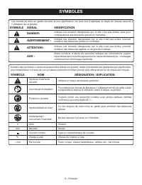
6 – Français SYMBOLES Les termes de mise en garde suivants et leur signification ont pour but d’expliquer le degré de risques associé à l’utilisation de ce produit. SYMBOLE SIGNAL SIGNIFICATION DANGER: Indique une situation dangereuse qui, si elle n’est pas évitée, aura pour conséquences des blessur...
Page 34 - GLOSSAIRE
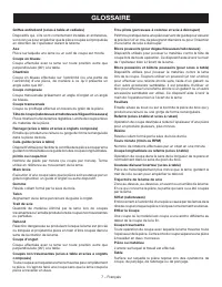
7 – Français GLOSSAIRE Trou pilote (perceuses à colonne et scie à découper) Petit trou pratiqué dans une pièce servant de guide pour assurer la précision d’un trou de plus grand diamètre ou pour l’insertion d’une lame de scie à découper. Blocs poussoirs (pour dégauchisseuses/raboteuses) Dispositifs ...
Page 35 - CARACTÉRISTIQUES; FICHE TECHNIQUE
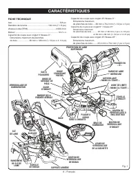
8 – Français CARACTÉRISTIQUES FICHE TECHNIQUE Axe ................................................................................ 5/8 po Diamètre de la lame................................... 184 mm (7-1/4 po) Vitesse à vide (RPM) ............................................... 4 000 /min Moteur .....
Page 37 - BUTÉES POSITIVES DE LA TABLE À ONGLETS; GÂCHETTE; OUTILS NÉCESSAIRES
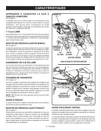
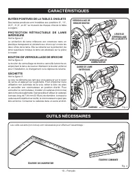
10 – Français CARACTÉRISTIQUES BUTÉES POSITIVES DE LA TABLE À ONGLETS Des butées positives sont installées aux positions 0°, 15°, 22,5°, 31,6°, et 45° se trouvent de chaque côté de la table à onglets. P R O T E C T I O N R É T R A C TA B L E D E L A M E INFÉRIEURE Voir la figure 3. La protection de ...
Page 38 - DÉBALLAGE
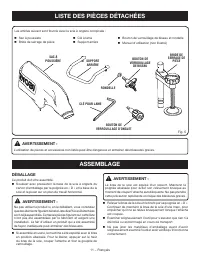
11 – Français LISTE DES PIÈCES DÉTACHÉES AVERTISSEMENT : L’utilisation de pièces et accessoires non listés peut être dangereux et entraîner des blessures graves. Fig. 5 Les articles suivant sont fournis avec la scie à onglets composés : Sac à poussiere Bride de serrage de pièce Clé à lame Su...
Page 39 - ASSEMBLAGE; TROUS DE FIXATION
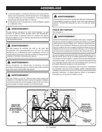
12 – Français ASSEMBLAGE AVERTISSEMENT : Cette scie peut basculer si sa tête est relâchée brusquement et assujettie à un plan de travail. Pour éviter des blessures graves, TOUJOURS assujettir la scie à un plan de travail stable. TROUS DE FIXATION Voir la figure 6. AVERTISSEMENT : Avant d’entreprendr...
Page 40 - BOUTON DE VERROUILLAGE D’ONGLET; CLÉ POUR LAME
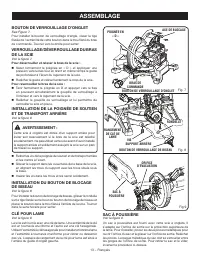
13 – Français ASSEMBLAGE BOUTON DE VERROUILLAGE D’ONGLET See Figure 7. Pour installer la bouton de verrouillage d’angle, visser la tige filetée de l’extrémité de cette bouton dans le trou fileté du bras de commande. Tourner vers la droite pour serrer. VERROUILLAGE/DÉVERROUILLAGE DU BRAS DE LA SCIE V...
Page 41 - BRIDE DE SERRAGE DE PIÈCE; INSTALLATION / REMPLACEMENT DE LA LAME
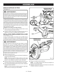
14 – Français ASSEMBLAGE BRIDE DE SERRAGE DE PIÈCE Voir la figure 10. AVERTISSEMENT : Dans certaines conditions, la bride de serrage de pièce peut interférerer avec le fonctionnement de la protection de lame. Toujours s’assurer du libre fonctionnement de la protection de lame avant de commencer la c...
Page 45 - UTILISATION
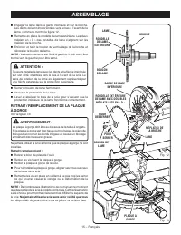
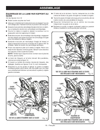
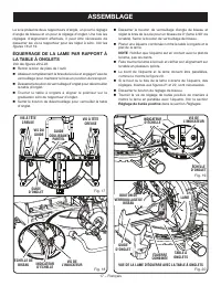
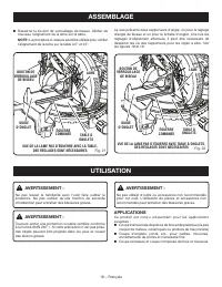
18 – Français ASSEMBLAGE Resserrer le bouton de verrouillage de biseau. Vérifier de nouveau l’alignement de la lame sur la table. NOTE : La procédure ci-dessus peut être utilisée pour vérifier l’alignement de la lame sur la table à 0° et 45°. La scie présente deux rapporteurs d’angle, un pour le r...
Page 46 - APPUYER SUR LES LOQUETS POUR
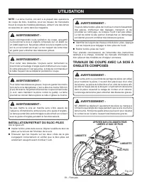
19 – Français UTILISATION AVERTISSEMENT : Toujours retirer le bloc-piles de l’outil au moment d’assembler des pièces, d’effectuer des réglages. transport, et de procéder au nettoyage, ou lorsque l’outil n’est pas utilisé. Le fait de retirer la pile permet d’empêcher un démarrage accidentel pouvant e...
Page 47 - COUPE D’ONGLET/COUPE TRANSVERSALE
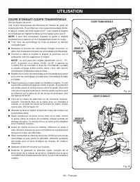
20 – Français UTILISATION COUPE TRANSVERSALE COUPE D’ONGLET COUPE D’ONGLET/COUPE TRANSVERSALE Voir les figures 24 et 25. Une coupe transversale est effectuée en travers du grain de la pièce de bois. Pour effectuer une coupe transversale droite, la table à onglets doit être réglée sur 0°. Les coupes ...
Page 48 - COUPE EN BISEAU
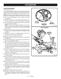
21 – Français UTILISATION COUPE EN BISEAU COUPE EN BISEAU Voir les figures 26 et 27. Une coupe en biseau est réalisée en travers du grain de la pièce, avec la lame en biais. Pour effectuer une coupe en biseau droite, la table à onglets doit être réglée sur 0° et la lame entre 0° et 45°. NOTE : Il pe...
Page 49 - COUPE D’ONGLET COMPOSÉ
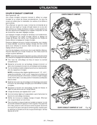
22 – Français UTILISATION COUPE D’ONGLET COMPOSÉ See Figures 28 - 29. Une coupe d’onglet composé consiste à utiliser un angle d’onglet et un angle de biseau simultanément. Ce type de coupe est utilisé pour la réalisation de cadres et de boîtes à pans inclinés. Pour effectuer ce type de coupe, le bra...
Page 50 - SUPPORT DE PIÈCES LONGUES; PIÈCE
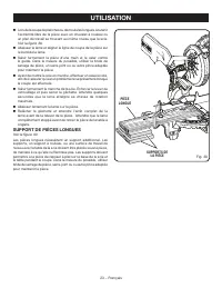
23 – Français UTILISATION Lors de la coupe de planches ou de moulures longues, soutenir l’extrémité libre de la pièce avec un chevalet à rouleau ou un plan de travail se trouvant au même niveau que la scie. Voir la figure 30. Abaisser la lame et aligner la ligne de coupe de la pièce sur le bord ...
Page 51 - COUPE D’ONGLETS COMPOSÉS; ANGLE
24 – Français UTILISATION COUPE D’ONGLETS COMPOSÉS Le tableau des réglages d’angles ci-dessous est conçu pour faciliter les réglages. Les coupes composées étant les plus difficiles à réaliser, des essais doivent être effectués sur des chutes et la coupe définitive ne doit être effectuée qu’après mûr...
Page 52 - COUPE DE MOULURE COURONNÉE
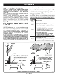
25 – Français UTILISATION PLAFOND M U R COIN INTÉRIEUR MOULURE COURONNÉE À PLAT SUR LA TABLE À ONGLETS 38 ° 52 ° GUIDE TABLE À ONGLETS CÔTÉ INFÉRIEUR CONTRE LE GUIDE = • CÔTÉ DROIT, COIN INTÉRIEUR • CÔTÉ GAUCHE, COIN EXTÉRIEUR GUIDE TABLE À ONGLETS Fig. 31 COIN EXTÉRIEUR CÔTÉ SUPÉRIEUR CONTRE LE GUI...
Page 53 - COUPE DE PIÈCES VOILÉES; INCORRECT
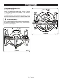
26 – Français UTILISATION COUPE DE PIÈCES VOILÉES Voir les figures 32 et 33. Lors de la coupe d’une pièce voilée, toujours s’assurer que son bord convexe est placé contre le guide, comme le montre la figure 32.Si une pièce voilée est placée dans le mauvais sens, comme illustré à la figure 33, elle p...
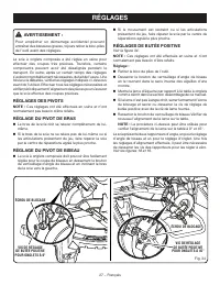
Page 54 - RÉGLAGES; RÉGLAGES DES PIVOTS
27 – Français RÉGLAGES AVERTISSEMENT : Pour empêcher un démarrage accidentel pouvant entraîner des blessures graves, tojours retirer le bloc-piles de l’outil avant des réglages. La scie à onglets composés a été réglée en usine pour effectuer des coupes très précises. Toutefois, certains composants p...
Page 55 - ENTRETIEN; ENTRETIEN GÉNÉRAL
28 – Français ENTRETIEN AVERTISSEMENT : Utiliser exclusivement des pièces identiques à celles d’origine pour les réparations. L’usage de toute autre pièce pourrait créer une situation dangereuse ou endommager l’outil. AVERTISSEMENT : Toujours porter une protection oculaire avec écrans latéraux certi...
Page 56 - REGLAS DE SEGURIDAD GENERALES; ÁREA DE TRABAJO; SEGURIDAD ELÉCTRICA
2 — Español REGLAS DE SEGURIDAD GENERALES ADVERTENCIA: Lea todas las advertencias, instrucciones, ilustraciones y especificaciones proporcionadas con esta herramienta eléctrica. No seguir las instrucciones indicadas a continuación puede provocar descargas eléctricas, incendios o lesiones graves. Gua...
Page 57 - SERVICIO
3 — Español REGLAS DE SEGURIDAD GENERALES REGLAS DE SEGURIDAD SIERRA INGLETEADORA que pueda afectar el funcionamiento de la herramienta eléctrica. Si está dañada la herramienta eléctrica, permita que la reparen antes de usarla. Numerosos accidentes son causados por herramientas eléctricas mal cuidad...
Page 58 - REGLAS DE SEGURIDAD SIERRA INGLETEADORA; ADVERTENCIAS DE SEGURIDAD ADICIONALES
4 — Español REGLAS DE SEGURIDAD SIERRA INGLETEADORA en ambos lados de la hoja de la sierra. No use esta sierra para cortar piezas demasiado pequeñas para sostener con la mano o por medio de la abrazadera de forma segura. Si coloca la mano muy cerca de la hoja de la sierra, hay mayor riesgo de lesion...
Page 60 - SÍMBOLOS; SÍMBOLO
6 — Español SÍMBOLOS Las siguientes palabras de señalización y sus significados tienen el objeto de explicar los niveles de riesgo relacionados con este producto. SÍMBOLO SEÑAL SIGNIFICADO PELIGRO: Indica una situación peligrosa inminente, la cual, si no se evita, causará la muerte o lesiones serias...
Page 61 - GLOSARIO DE TÉRMINOS
7 — Español GLOSARIO DE TÉRMINOS Este es un corte en el cual la hoja no corta la pieza de trabajo en dos pedazos. Agujero guía (taladradoras de columna y sierras caladoras) Es un agujero pequeño taladrado en una pieza de trabajo, el cual sirve como guía para taladrar con precisión agujeros más grand...
Page 62 - CARACTERÍSTICAS; ESPECIFICACIONES DEL PRODUCTO
8 — Español CARACTERÍSTICAS ESPECIFICACIONES DEL PRODUCTO Árbol ..........................................................................5/8 pulg. Diámetro de la hoja ............................... 184 mm (7-1/4 pulg.)Velocidad en vacío (RPM) ....................................... 4 000 /minMotor...
Page 64 - TOPES DE LA MESA DE INGLETES; HERRAMIENTAS NECESARIAS
10 — Español CARACTERÍSTICAS TOPES DE LA MESA DE INGLETES Hay topes a 0°, 15°, 22,5°, 31,6°, y 45° a ambos lados, izquierdo y derecho, de la mesa de ingletes. PROTECCIÓN INFERIOR AUTORRETRAÍBLE DE LA HOJA Vea la figura 3. La protección inferior de la hoja está hecha de plastico transparente resisten...
Page 65 - DESEMPAQUETADO
11 — Español LISTA DE PIEZAS SUELTAS ADVERTENCIA: El empleo de aditamentos o accesorios no enumerados arriba podría ser peligros y causar lesiones serias. Vienen incluidos los siguientes artículos con la sierra ingleteadora combinada: Saco captapolvo Prensa de trabajo Llave de hoja Soporte t...
Page 66 - ARMADO; AGUJEROS DE MONTAJE
12 — Español ARMADO ADVERTENCIA: Esta sierra puede volcarse si se suelta súbitamente la cabeza de la misma y la sierra no está asegurada a una superficie de trabajo. SIEMPRE asegure esta sierra a una superficie de trabajo estable antes de usarla para evitar lesiones serias. AGUJEROS DE MONTAJE Vea l...
Page 67 - MANIJA DE FIJACIÓN DE INGLETE; LLAVE DE HOJA
13 — Español ARMADO MANIJA DE FIJACIÓN DE INGLETE See Figure 7. Para instalar la manija de fijación de inglete, introduzca el vástago roscado del extremo de la manija de fijación de inglete en el agujero roscado del brazo de control. Para apretarlo gírelo a la derecha. PROCEDIMIENTO DE TRABA Y DESTR...
Page 68 - PRENSA DE TRABAJO; PARA INSTALAR O REEMPLAZAR LA HOJA
14 — Español ARMADO PRENSA DE TRABAJO Vea la figura 10. ADVERTENCIA: En algunas operaciones el conjunto de la prensa de trabajo puede interferir en el movimiento del conjunto de protección de la hoja. Siempre asegúrese de que no haya interferencia en el movimiento de la protección de la hoja antes d...
Page 69 - EXTRACCIÓN/REEMPLAZO DE LA PLACA
15 — Español ARMADO Acomode la hoja de la sierra dentro de la protección inferior, y móntela en el husillo. Los dientes de la sierra apuntan hacia abajo en la parte delantera de la sierra, como se muestra en la figura 12. Retire la arandela exterior de la hoja. Los dos partes planas en “D” de la...
Page 70 - ESCUADRADO DE LA HOJA CON LA GUÍA
16 — Español ARMADO ESCUADRADO DE LA HOJA CON LA GUÍA Vea las figuras 14 a 19. Retire de la herramienta el paquete de baterías. Tire del brazo de la sierra completamente hacia abajo y enganche el pasador de seguridad para asegurar el brazo en la posición de transporte. Afloje la perilla de fij...
Page 71 - ESCUADRADO DE LA HOJA CON LA MESA
17 — Español ARMADO La sierra dispone de dos indicadores de escala, uno en la escala de biseles y uno en la de ingletes. Después de efectuar los ajustes de escuadrado, puede ser necesario aflojar los tornillos de la indicador y reajustarlos a cero. Vea la figura 18. ESCUADRADO DE LA HOJA CON LA MESA...
Page 72 - FUNCIONAMIENTO; APLICACIONES
18 — Español PERILLA DE FIJACIÓN DE BISEL ARMADO Ajuste el tornillo de ajuste del tope para alinear la hoja con la escuadra. Vea el apartado Ajuste de Los Topes en la sección Ajustes . Vuelva a apretar la perilla de fijación de inglete. Vuelva a revisar la alineación de la hoja con la mesa. NOTA...
Page 74 - PARA REALIZAR CORTES DE INGLETE /
20 — Español FUNCIONAMIENTO CORTE TRANSVERSAL CORTE DE INGLETE PARA REALIZAR CORTES DE INGLETE / TRANSVERSALES Vea las figuras 24 y 25. Los cortes transversales se efectúan cortando a través de la veta de la pieza de trabajo. Un corte transversal recto se efectúa con la mesa de ingletes ajustada en ...
Page 75 - PARA CORTAR A BISEL
21 — Español FUNCIONAMIENTO PARA CORTAR A BISEL Vea las figuras 26 y 27.Un corte en bisel se efectúa cortando a través de la fibra de la pieza de trabajo con la hoja en ángulo con dicha pieza. Un corte en bisel recto se efectúa con la mesa de ingletes en la posición de cero grados y la hoja a un áng...
Page 76 - CORTE EN INGLETE COMBINADO
22 — Español FUNCIONAMIENTO PARA EFECTUAR UN CORTE A INGLETE COMBINADO Vea las figuras 28 y 29. Un corte en bisel combinado es un corte efectuado a un ángulo de inglete y a un ángulo de bisel al mismo tiempo. Este tipo de corte se usa para elaborar marcos de cuadros, cortar molduras y elaborar cajas...
Page 77 - PARA APOYAR LAS PIEZAS DE TRABAJO; PIEZA DE
23 — Español FUNCIONAMIENTO Al cortar tablas o molduras largas, apoye el extremo opuesto del material sobre un soporte de rodillo o con una superficie de trabajo a nivel con la mesa de la sierra. Vea la figura 30. Baje la hoja de corte y alinee la línea de corte de la pieza de trabajo con el bor...
Page 78 - CÓMO EFECTUAR CORTES A INGLETE COMBINADOS; INCLINACIÓN
24 — Español FUNCIONAMIENTO CÓMO EFECTUAR CORTES A INGLETE COMBINADOS Como ayuda para realizar los ajustes correctos, se suministra la siguiente tabla de ángulos combinados. Puesto que los cortes combinados son los más difíciles de obtener, deben efectuarse cortes de prueba en material de desecho, a...
Page 79 - CÓMO CORTAR MOLDURAS DE CORONA
25 — Español Al cortar molduras de corona con este método, el ángulo de bisel debe fijarse a 33,85°. El ángulo de inglete debe fijarse a 31,62°, a la derecha o izquierda, según el corte deseado para cada aplicación en particular. En la tabla mostrada abajo encontrará los ajustes correctos de los áng...
Page 80 - CÓMO CORTAR MATERIAL TORCIDO; FORMA CORRECTA
26 — Español FUNCIONAMIENTO CÓMO CORTAR MATERIAL TORCIDO Vea las figuras 32 y 33. Al cortar material torcido, asegúrese siempre de que esté situado sobre la mesa de ingletes con el canto convexo apoyado contra la guía, como se muestra en la figura 32.Si se coloca de forma incorrecta como se muestra ...
Page 81 - AJUSTES; AJUSTES DE LOS PIVOTES
27 — Español AJUSTES ADVERTENCIA: Para evitar un arranque accidental que podría causar lesiones corporales serias, siempre desmonte de la herramienta el paquete de baterías al antes de efectuar ajustes. La sierra ingleteadora combinada ha sido ajustada en la fábrica para producir cortes muy exactos....
Page 82 - MANTENIMIENTO; MANTENIMIENTO GENERAL
28 — Español MANTENIMIENTO ADVERTENCIA: Al dar servicio a la unidad, sólo utilice piezas de repuesto idénticas. El empleo de piezas diferentes puede causar un peligro o dañar el producto. ADVERTENCIA: Cuando utilice este producto, siempre póngase protección ocular con protección lateral con la marca...