Page 2 - Save all warnings and instructions for future reference.; WORK AREA SAFETY; Keep work area clean and well lit.; ELECTRICAL SAFETY; Do not expose power tools to rain or wet conditions.; PERSONAL SAFETY; GENERAL SAFETY RULES; POWER TOOL USE AND CARE
2 − English WARNING: Read all safety warnings, instructions, illustrations and specifications provided with this power tool. Failure to follow all instructions listed below may result in electric shock, fire and/or serious injury. Save all warnings and instructions for future reference. The term “po...
Page 3 - tool repaired before use.; BATTERY TOOL USE AND CARE; Use battery only with charger listed.; SERVICE; Never service damaged battery packs.
3 − English GENERAL SAFETY RULES tool repaired before use. Many accidents are caused by poorly maintained power tools. Keep cutting tools sharp and clean. Properly main- tained cutting tools with sharp cutting edges are less likely to bind and are easier to control. Use the power tool, accessori...
Page 4 - MITER SAW SPECIFIC SAFETY RULES; the workpiece into the blade or cut ”freehand” in any; Cut only one workpiece at a time.; Save these instructions.
4 − English MITER SAW SPECIFIC SAFETY RULES Miter saws are intended to cut wood or wood-like products, they cannot be used with abrasive cut-off wheels for cutting ferrous material such as bars, rods, studs, etc. Abrasive dust causes moving parts such as the lower guard to jam. Sparks from abrasiv...
Page 5 - ADDITIONAL SAFETY RULES
5 − English ADDITIONAL SAFETY RULES Inspect tool cords periodically. If damaged, have re- paired by a qualified service technician at an authorized service facility. Repair or replace a damaged or worn cord immediately. Stay constantly aware of cord location and keep it well away from the rotating...
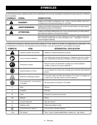
Page 6 - SYMBOLS
6 − English Some of the following symbols may be used on this tool. Please study them and learn their meaning. Proper interpretation of these symbols will allow you to operate the tool better and safer. SYMBOL NAME DESIGNATION/EXPLANATION Safety Alert Indicates a potential personal injury hazard. Re...
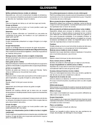
Page 7 - GLOSSARY OF TERMS
7 − English GLOSSARY OF TERMS Push Blocks (for jointer planers) Device used to feed the workpiece over the jointer planer cutterhead during any operation. This aid helps keep the operator’s hands well away from the cutterhead. Push Blocks (for table saws) Device used to hold the workpiece during cut...
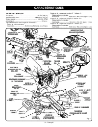
Page 8 - FEATURES; PRODUCT SPECIFICATIONS
8 − English 45 30 15 0 45 30 15 0 FEATURES PRODUCT SPECIFICATIONS Arbor Hole ................................................................. 5/8 in.Blade Diameter ....................................................... 7-1/4 in.No Load Speed ........................................3,600/min. (RPM)...
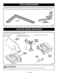
Page 11 - LOOSE PARTS LIST; TOOLS NEEDED
11 − English BLADE WRENCH LOOSE PARTS LIST Fig. 6 Work Clamp Side Handles (2) with screws Dust Bag Blade Wrench WORK CLAMP DUST BAG The following items are included with the tool: WARNING: The use of attachments or accessories not listed might be hazardous and could cause serious personal in...
Page 12 - ASSEMBLY; UNPACKING
12 − English ASSEMBLY UNPACKING This product requires assembly. Carefully lift saw from the carton by the carrying handle and the saw base, and place it on a level work surface. WARNING: Do not use this product if any parts on the Loose Parts List are already assembled to your product when you unp...
Page 13 - MOUNTING HOLES; To use the depth stop:
13 − English ASSEMBLY TRACE HOLES AT THESE LOCATIONS FOR HOLE PATTERN Fig. 7 MOUNTING SURFACE SAW BASE TRACE HOLES AT THESE LOCATIONS FOR HOLE PATTERN MOUNTING HOLES See Figure 7. WARNING: Before starting any cutting operation, clamp or bolt your miter saw to a workbench or an approved miter saw sta...
Page 14 - LOCKING/UNLOCKING THE SAW ARM; To unlock and raise the saw arm:; DUST BAG
14 − English 45 30 15 0 45 30 15 0 Fig. 10 DUST BAG EXHAUST PORT BLADE WRENCH 45 30 15 0 Fig. 9 LOCK PIN “D” HANDLE LOCKING/UNLOCKING THE SAW ARM See Figure 9. When locking and unlocking the saw arm, it is not necessary to loosen the depth control knob. To unlock and raise the saw arm: Firmly gras...
Page 15 - WORK CLAMP; To install the work clamp:; SIDE HANDLES; To install side handles:
15 − English Fig. 12 HEX SCREW SIDE HANDLE BASE 45 30 15 0 Fig. 11 BASE WORK CLAMP WORK CLAMP KNOB Fig. 13 SIDE HANDLE BASE HEX SCREW ASSEMBLY WORK CLAMP See Figure 11. WARNING: In some operations, the work clamp assembly may in-terfere with the operation of the blade guard assembly. Always make sur...
Page 16 - TO INSTALL/REPLACE THE BLADE
16 − English TO INSTALL/REPLACE THE BLADE See Figures 14 - 15. The blade is shipped installed on this miter saw model. In-structions have been included for reference when changing or replacing blades. WARNING: A 7-1/4 in. blade is the maximum blade capacity of the saw. Never use a blade that is too ...
Page 17 - Never operate the saw without all guards securely; SQUARING THE BLADE TO THE FENCE
17 − English 45 30 15 0 WARNING: Make sure the spindle lock button is not engaged be-fore reconnecting saw into power source. Never engage spindle lock button when blade is rotating. REMOVING/REPLACING THE THROAT PLATE See Figure 16. WARNING: The throat plate must be below the miter table. If the th...
Page 19 - SQUARING THE BLADE TO THE MITER TABLE; Positive Stop Adjust-
19 − English Loosen the fence screw and slide the partial sliding miter fence toward the blade to access the socket head screws securing the left miter fence to the table. Using the blade wrench provided, loosen the socket head screws that secure the miter fence to the miter table. Rotate the ...
Page 20 - OPERATION; BATTERY
20 − English WARNING: Do not allow familiarity with tools to make you careless. Remember that a careless fraction of a second is suf-ficient to inflict serious injury. WARNING: Always wear eye protection with side shields marked to comply with ANSI Z87.1. Failure to do so could result in objects bei...
Page 22 - TO BEVEL CUT
22 − English Fig. 29 as you rotate the control arm. The control arm will seat itself in one of the positive stop notches, located in the miter table base. Place the workpiece flat on the miter table with one edge securely against the fence. If the board is warped, place the convex side against the...
Page 23 - TO COMPOUND MITER CUT; COMPOUND MITER CUT
23 − English Release the switch trigger and allow the saw blade to stop rotating before raising the blade out of workpiece. Wait until the electric brake stops blade from turning before removing the workpiece from miter table. TO COMPOUND MITER CUT See Figures 30 - 31. A compound miter cut is a cu...
Page 24 - NEVER
24 − English Lower the blade and align the cutting line on the workpiece with the edge of saw blade or the blade shadow. Grasp the stock firmly with one hand and secure it against the fence. Use the optional work clamp or a C-clamp to secure the workpiece when possible. Before turning on the s...
Page 25 - MAKING AN AUXILIARY FENCE; MUST
25 − English OPERATION With the saw off, grasp the saw handle firmly then pull the saw forward until the blade arbor (center of the saw blade) is over the front of the workpiece or until the saw is fully extended. Depress the trigger lockout lever and squeeze the switch trigger. Allow several se...
Page 26 - CUTTING COMPOUND MITERS; PITCH
26 − English OPERATION CUTTING COMPOUND MITERS To aid in making the correct settings, the compound angle setting chart below has been provided. Since compound cuts are the most difficult to accurately obtain, trial cuts should be made in scrap material, and much thought and planning made, prior to m...
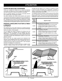
Page 27 - CUTTING CROWN MOLDING
27 − English Fig. 36 31.6° either right or left, depending on the desired cut for the application. See the chart below for correct angle settings and correct positioning of crown molding on miter table.The settings in the chart below can be used for cutting All Standard (U.S.) crown molding with 52°...
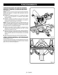
Page 29 - RIGHT; CUTTING WARPED MATERIAL
29 − English RIGHT VERTICALLY CUTTING BASE MOLDING AGAINST THE MITER FENCE See Figure 40. NOTE: It may be necessary to adjust the partial sliding miter fence to ensure proper clearance prior to making the cut. Set the bevel angle at 0° and the miter angle at 45° to either the left or the right. (F...
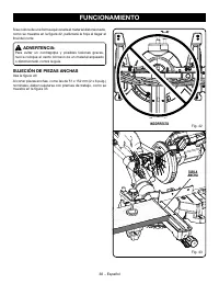
Page 30 - CLAMPING WIDE WORKPIECES; WRONG
30 − English If the warped material is positioned the wrong way as shown in figure 42, it will pinch the blade near the completion of the cut. WARNING: To avoid a kickback and to avoid serious personal injury, never position the concave edge of bowed or warped material against the fence. CLAMPING WI...
Page 31 - ADJUSTMENTS; PIVOT ADJUSTMENTS; AUTHORIZED SERVICE CENTER.; TO ADJUST THE BEVEL PIVOT; AUTHORIZED SERVICE; POSITIVE STOP ADJUSTMENTS
31 − English POSITIVE STOP ADJUSTMENT SCREW FOR 45 ° ANGLES ADJUSTMENTS WARNING: Before performing any adjustment, make sure the tool is unplugged from the power supply. Failure to heed this warning could result in serious personal injury. The compound miter saw has been adjusted at the factory for ...
Page 32 - MAINTENANCE; GENERAL MAINTENANCE
32 − English MAINTENANCE WARNING: When servicing, use only identical replacement parts. Use of any other part can create a hazard or cause product damage. WARNING: Always wear eye protection with side shields marked to comply with ANSI Z87.1 during product operation. If operation is dusty, also wear...
Page 33 - SÉCURITÉ DU LIEU DE TRAVAIL; SÉCURITÉ ÉLECTRIQUE; RÈGLES DE SÉCURITÉ GÉNÉRALES; SÉCURITÉ PERSONNELLE
2 − ran ais AVERTISSEMENT : Lire les avertissements de sécurité, les instructions et les précisions et consulter les illustrations fournis avec cet outil électrique. e ait de ne pas se con or er l ense ble des consignes pr sent es ci dessous ris ue d entra ner des d charges lectri ues un incendie et...
Page 34 - DÉPANNAGE; RÈGLES DE SÉCURITÉ DU SCIE À ONLGETS
3 − ran ais RÈGLES DE SÉCURITÉ GÉNÉRALES Ranger les outils motorisés hors de la portée des enfants et ne laisser personne n’étant pas familiarisé avec l’outil ou ces instructions utiliser l’outil. ans les ains de personnes n ayant pas re u des instructions ad uates les outils sont dangereu . Ent...
Page 36 - RÈGLES DE SÉCURITÉ SUPLÉMENTAIRES
5 − ran ais type incorrect. a taille a i u de la e pou ant tre utilis e sur cet outil est de 184 7 1 4 po . S ’ a s s u re r q u e t o u s l e s d i s p o s i t i f s d e p ro t e c t i o n fonctionnent correctement avant d’effectuer une coupe. Ne jamais toucher la lame ou les pi ces en ou e ent...
Page 37 - SYMBOLES
6 − ran ais ertains des sy boles ci dessous peu ent tre utilis s sur l outil. eiller les tudier et apprendre leur signi ication. ne interpr tation correcte de ces sy boles per ettra d utiliser l outil plus e icace ent et de r duire les ris ues. SYMBOLE NOM DÉSIGNATION / EXPLICATION y bole d alerte d...
Page 38 - GLOSSAIRE
7 − ran ais GLOSSAIRE Trou pilote (perceuses à colonne et scie à découper) etit trou prati u dans une pi ce ser ant de guide pour assurer la pr cision d un trou de plus grand dia tre ou pour l insertion d une la e de scie d couper. Blocs poussoirs (pour dégauchisseuses/raboteuses) ispositi s utilis ...
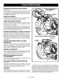
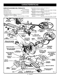
Page 39 - CARACTÉRISTIQUES; FICHE TECHNIQUE
8 − ran ais 45 30 15 0 CARACTÉRISTIQUES apacit de coupe a ec onglet 45 biseau 0 ailles de bois no inales a i ales ........................ 50 8 152 4 2 po 6 po apacit de coupe a ec onglet 0 biseau 45 ailles de bois no inales a i ales ......................... 50 8 254 2 po 10 po apacit de coupe a ec...
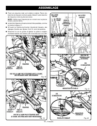
Page 43 - ASSEMBLAGE; DÉBALLAGE
12 − ran ais ASSEMBLAGE DÉBALLAGE his product re uires asse bly. ortir soigneuse ent la scie du carton en la tenant par la poign e de transport et la base de la scie et la poser sur un plan de tra ail hori ontal. AVERTISSEMENT : Ne pas utiliser le produit si en le d ballant ous constate ue des l e...
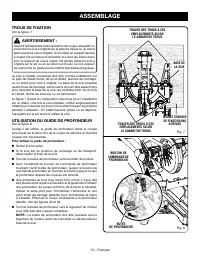
Page 44 - TROUS DE FIXATION
13 − ran ais ASSEMBLAGE ig. 8 TROUS DE FIXATION Voir la figure 7. AVERTISSEMENT : ant d entreprendre toute op ration de coupe assu ettir ou boulonner la scie onglets sur le plan de tra ail ou un stand approu pour scie onglets. i on utilise un support de scie onglet lire le anuel d utilisation et sui...
Page 45 - SAC À POUSSIÈRE
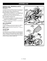
14 − ran ais VERROUILLAGE / DÉVERROUILLAGE DU BRAS DE LA SCIE Voir la figure 9. l n est pas n cessaire de rel cher le bouton de co ande de pro ondeur pour errouiller ou d errouiller le bras de la scie. Pour déverrouiller et relever le bras de la scie : aisir er e ent la poign e en et appli uer une...
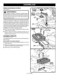
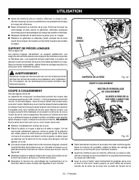
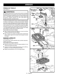
Page 46 - BRIDE DE SERRAGE DE PIÈCE; POIGNÉES LATÉRALES
15 − ran ais BOUTON DE SERRAGE DE PIÈCE BRIDE DE SERRAGE DE PIÈCE Voir la figure 11. AVERTISSEMENT : ans certaines conditions la bride de serrage de pi ce peut perturber le onctionne ent de la protection de la e. ou ours s assurer du libre onctionne ent de la protection de la e a ant de co encer la ...
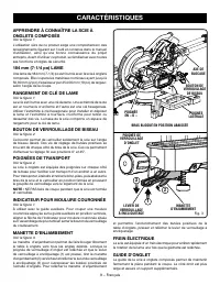
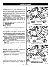
Page 48 - RÉGLAGE DU PIED DE SUPPORT
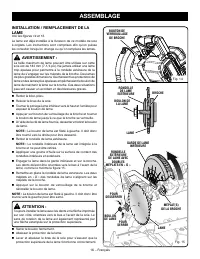
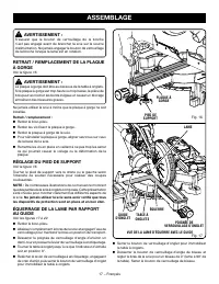
17 − ran ais AVERTISSEMENT : assurer ue le bouton de errouillage de la broche n est pas engag a ant de brancher la scie sur la source d ali entation. Ne a ais engager le bouton de errouillage de la broche lors ue la la e est en rotation. RETRAIT / REMPLACEMENT DE LA PLAQUE À GORGE Voir la figure 16....
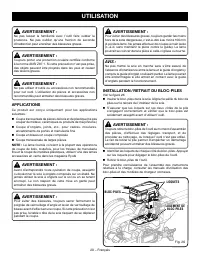
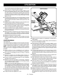
Page 51 - UTILISATION; APPLICATIONS; LOGEMENT DE
20 − ran ais UTILISATION AVERTISSEMENT : Ne pas laisser la a iliarit a ec l outil aire oublier la prudence. Ne pas oublier u une raction de seconde d inattention peut entra ner des blessures gra es. AVERTISSEMENT : ou ours porter une protection oculaire certi i e con or e la nor e N 87.1. i cette pr...
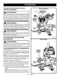
Page 52 - POUR COUPES D’ONGLETS / TRANSVERSALES
21 − ran ais TRAVAUX DE COUPE AVEC LA SCIE À ONGLETS COMPOSÉS AVERTISSEMENT : i un serre oint ou une bride de serrage de pi ce est utilis pour aintenir la pi ce il ne doit tre plac ue d un c t de la la e. a pi ce doit tre libre d un c t de la la e a in u elle ne ris ue pas de la blo uer. n pince ent...
Page 53 - COUPE EN BISEAU; BRIDE DE
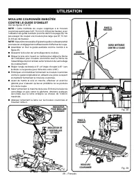
22 − ran ais de co ande reposera auto ati ue ent dans l un des crans d arr t situ sur la base de la table onglets. lacer la pi ce couper plat sur la table onglet l un de ses bords solide ent appuy contre le guide. i la planche est oil e placer le c t con e e contre le guide. i le bord conca e d un...
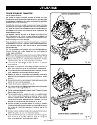
Page 54 - COUPE D’ONGLET COMPOSÉ
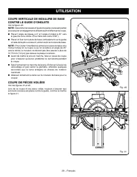
23 − ran ais COUPE D’ONGLET COMPOSÉ Voir les figures 30 et 31. ne coupe d onglet co pos consiste utiliser un angle d onglet et un angle de biseau si ultan ent. e type de coupe est utilis pour la r alisation de cadres de bo tes pans inclin s et certains tra au de charpente. our e ectuer ce type de co...
Page 57 - COUPE D’ONGLETS COMPOSÉS; ANGLE
26 − ran ais COUPE D’ONGLETS COMPOSÉS e tableau des r glages d angles ci dessous est con u pour aciliter les r glages. es coupes co pos es tant les plus di iciles r aliser des essais doi ent tre e ectu s sur des chutes et la coupe d initi e ne doit tre e ectu e u apr s re r le ion et plani ication. ...
Page 58 - COUPE DE MOULURE COURONNÉE
27 − ran ais d onglet doit tre r gl 31 6 droite ou gauche sui ant le sens de coupe n cessaire pour l application. onsulter le tableau ci dessous pour les r glages d angle et le positionne ent corrects de la oulure sur la table. es r glages indi u s au tableau ci dessous peu ent tre utilis s pour la ...
Page 60 - COUPE DE PIÈCES VOILÉES; CORRECT
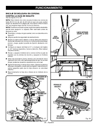
29 − ran ais COUPE VERTICALE DE MOULURE DE BASE CONTRE LE GUIDE D’ONGLETS Voir la figure 40. NOTE : l peut tre n cessaire d a uster le guide coulissant partiel pour assurer un d gage ent su isant a ant d e ectuer la coupe. lacer l angle de biseau 0 et l angle d onglet 45 ers la gauche ou la droite...
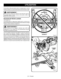
Page 61 - FIXATION DE PIÈCES LARGES; INCORRECT
30 − ran ais i une pi ce oil e est plac e dans le au ais sens co e illustr la igure 42 elle pincera la la e ers la in de la coupe. AVERTISSEMENT : our iter les ris ues de rebond et de blessures gra es ne a ais placer le bord conca e d une pi ce oil e ou d or e contre le guide. FIXATION DE PIÈCES LAR...
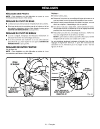
Page 62 - RÉGLAGES; RÉGLAGES DES PIVOTS; RÉGLAGE DU PIVOT DE BISEAU; RÉGLAGES DE BUTÉE POSITIVE
31 − ran ais VIS DE RÉGLAGE DE BUTÉE POSITIVE POUR ONGLETS À 45° RÉGLAGES RÉGLAGES DES PIVOTS NOTE : es r glages ont t e ectu s en usine et n ont nor ale ent pas besoin d tre re aits. RÉGLAGE DU PIVOT DE BRAS e bras de la scie doit se rele er co pl te ent de lui e. i le bras de la scie ne se rel...
Page 63 - ENTRETIEN; ENTRETIEN GÉNÉRAL
32 − ran ais ENTRETIEN AVERTISSEMENT : tiliser e clusi e ent des pi ces d origine pour les r parations. usage de toute autre pi ce pourrait cr er une situation dangereuse ou endo ager le produit. AVERTISSEMENT : ou ours porter une protection oculaire certi i e con or e la nor e N 87.1 lors de l util...
Page 64 - REGLAS DE SEGURIDAD GENERALES; SEGURIDAD ELÉCTRICA
2 − Espa ol REGLAS DE SEGURIDAD GENERALES ADVERTENCIA: Lea todas las advertencias, instrucciones, ilustraciones y especificaciones proporcionadas con esta herramienta eléctrica. No seguir las instrucciones indicadas a continuaci n puede pro ocar descargas el ctricas incendios o lesiones gra es. Guar...
Page 68 - SEÑAL
6 − Espa ol Es posible ue se e pleen en esta herra ienta algunos de los siguientes s bolos. e suplica os estudiarlos y aprender su signi icado. na correcta interpretaci n de estos s bolos le per itir utili ar e or y de anera s segura la herra ienta. lerta de seguridad ndica un peligro posible de les...
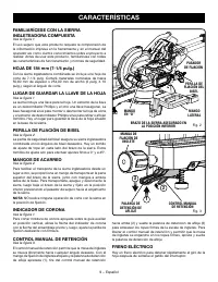
Page 70 - CARACTERÍSTICAS
8 − Espa ol CARACTERÍSTICAS Ori icio del e e .................................................... 16 5 8 pulg. i etro de la ho a ...................................... 184 7 1 4 pulg. elocidad en ac o ..............................................3 600 in orriente de entrada ...........................
Page 71 - mm
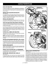
9 − Espa ol 45 30 15 0 CARACTERÍSTICAS Vea la figura 1. El uso seguro ue este producto re uiere la co prensi n de la in or aci n i presa en la herra ienta y en el anual del operador as co o ciertos conoci ientos sobre el proyecto a reali ar. ntes de usar este producto a iliar cese con todas las cara...
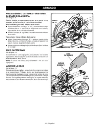
Page 73 - LISTA DE PIEZAS SUELTAS
11 − Espa ol LISTA DE PIEZAS SUELTAS ADVERTENCIA: El e pleo de adita entos o accesorios no enu erados arriba podr a ser peligros y causar lesiones serias. e necesitan las siguientes herra ientas no ienen incluidas para e ectuar a ustes o instalar la ho a ig. 5 ESCUADRA DE COMBINACIÓN ESCUADRA ig. 6 ...
Page 79 - DE GARGANTA; DE INGLETES
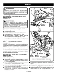
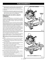
17 − Espa ol 45 30 15 0 ig. 16 ig. 17 GUÍA DE INGLETES MANIJA DE FIJACIÓN DE INGLETE ESCUADRA VISTA A DE LA HOJA A ESCUADRA CON LA GUÍA PLACA DE LA GARGANTA PIED DE SUPPORT HOJA MESA DE INGLETES ADVERTENCIA: seg rese de ue el bot n del seguro del husillo no est opri ido antes de ol er a conectar la ...
Page 83 - TRANSVERSALES
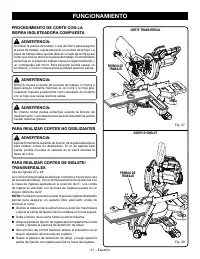
21 − Espa ol ADVERTENCIA: l utili ar la prensa de traba o o una de ano para asegurar la pie a de traba o su ete sta s lo en un lado de la ho a. a pie a de traba o debe uedar libre en un lado de la ho a para e itar ue sta se atore en la pie a de traba o. El atora iento de la ho a en la pie a de traba...
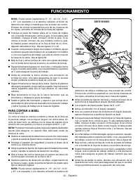
Page 86 - LARGAS
24 − Espa ol ig. 32 ig. 33 PIEZA DE TRABAJO LARGA SOPORTES DE LA PIEZA DE TRABAJO CORTE POR DESLIZAMIENTO DESLIZAR EL BRAZO DE LA SIERRA HACIA DELANTE Y, SEGUIDAMENTE, PRESIONAR HACIA ABAJO PERILLA DE FIJACIÓN DE LA CORREDERA de la tabla se iniera sobre la ho a al inal del corte la atorar a. Vea las...
Page 91 - CORRECTA
29 − Espa ol Vea la figura 40. uede ser necesario a ustar la gu a de ingletes desli able parcial para asegurar un espacio libre adecuado antes de e ectuar el corte. Estable ca el ngulo del bisel en 0 y el ngulo del inglete en 45 ya sea a la i uierda o a la derecha. ara reali ar es uinas de 90 . ...