Page 2 - GENERAL SAFETY RULES; Save all warnings and instructions for future reference.; WORK AREA SAFETY; Keep work area clean and well lit.; ELECTRICAL SAFETY; Do not expose power tools to rain or wet conditions.; PERSONAL SAFETY
2 - English GENERAL SAFETY RULES WARNING: Read all safety warnings, instructions, illustrations and specifications provided with this power tool. Failure to follow all instructions listed below may result in electric shock, fire and/or serious injury. Save all warnings and instructions for future re...
Page 3 - the workpiece into the blade or cut ”freehand” in any; Cut only one workpiece at a time.; Keep cutting tools sharp and clean.; SERVICE
3 - English GENERAL SAFETY RULES MITER SAW SPECIFIC SAFETY RULES Miter saws are intended to cut wood or wood-like products, they cannot be used with abrasive cut-off wheels for cutting ferrous material such as bars, rods, studs, etc. Abrasive dust causes moving parts such as the lower guard to jam...
Page 4 - Save these instructions.; ADDITIONAL SAFETY RULES; Inspect extension cords periodically; MITER SAW SPECIFIC SAFETY RULES
4 - English Provide adequate support such as table extensions, saw horses, etc. for a workpiece that is wider or longer than the table top. Workpieces longer or wider than the miter saw table can tip if not securely supported. If the cut-off piece or workpiece tips, it can lift the lower guard or ...
Page 6 - SYMBOLS
6 - English Some of the following symbols may be used on this tool. Please study them and learn their meaning. Proper interpreta-tion of these symbols will allow you to operate the tool better and safer. SYMBOL NAME DESIGNATION/EXPLANATION Safety Alert Indicates a potential personal injury hazard. R...
Page 7 - EXTENSION CORDS; Cord Length; DOUBLE INSULATION; ELECTRICAL CONNECTION; ELECTRICAL
7 - English EXTENSION CORDS When using a power tool at a considerable distance from a power source, be sure to use an extension cord that has the capacity to handle the current the product will draw. An undersized cord will cause a drop in line voltage, resulting in overheating and loss of power. Us...
Page 8 - GLOSSARY OF TERMS
8 - English GLOSSARY OF TERMS Pilot Hole (drill presses and scroll saws) A small hole drilled in a workpiece that serves as a guide for drilling large holes accurately or for insertion of a scroll saw blade. Push Blocks (jointer planers) Device used to feed the workpiece over the jointer planer cutt...
Page 9 - FEATURES; PRODUCT SPECIFICATIONS
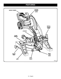
9 - English Fig. 1 FEATURES PRODUCT SPECIFICATIONS Arbor .......................................................................... 5/8 in.Blade Diameter ....................................................... 7-1/4 in.No Load Speed (RPM) ...................................... 5,100 /min. Input .......
Page 12 - PARTIAL SLIDING FENCE
12 - English FEATURES PARTIAL SLIDING FENCE The partial sliding fence on your compound miter saw has been provided to help secure the workpiece when making straight cuts.The sliding feature makes it easy to adjust the position of the partial fence. Loosen the fence screw before attempt-ing to slide ...
Page 14 - UNPACKING; ASSEMBLY
14 - English enced the settings, refer to specific procedures explained later in this manual. If any parts are damaged or missing, please call 1-800-525-2579 for assistance. WARNING: If any parts are damaged or missing do not operate this product until the parts are replaced. Use of this product w...
Page 15 - To unlock and raise the saw arm:; INSTALLING THE BEVEL LOCK KNOB
15 - English Fig. 10 Fig. 9 WARNING: This saw can tip over if the saw head is released suddenly and the saw is not secured to a work surface. ALWAYS secure this saw to a stable work surface before any use to avoid serious personal injury. MOUNTING HOLES See Figure 8. WARNING: Before starting any cut...
Page 16 - tooltip; DUST BAG; To install the work clamp:; TO INSTALL/REPLACE THE BLADE
16 - English tooltip DUST BAG See Figure 11. A dust bag is provided for use on the miter saw. It fits over the exhaust port on the upper blade guard. Squeeze the two metal clips to open the mouth of the bag and slide it on the exhaust port. Release the clips. The metal ring in the bag should lock in...
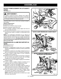
Page 18 - REMOVING/REPLACING THE THROAT PLATE; Never operate the saw without all guards securely; SQUARING THE BLADE TO THE FENCE
18 - English VIEW OF BLADE SQUARE WITH FENCE MITER TABLE BLADE SQUARE MITER FENCE THROAT PLATE REMOVING/REPLACING THE THROAT PLATE See Figure 15. WARNING: The throat plate must be below the miter table. If the throat plate is too high or too low, the workpiece can catch on the uneven edges resulting...
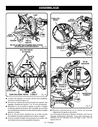
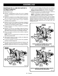
Page 20 - SQUARING THE BLADE TO THE MITER TABLE; Positive Stop Adjust-
20 - English SQUARING THE BLADE TO THE MITER TABLE See Figures 22 - 24. Unplug the saw. Pull the saw arm all the way down and engage the lock pin to hold the saw arm in transport position. Loosen the miter lock knob approximately one-half turn and press the detent release button. Rotate the ...
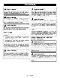
Page 21 - APPLICATIONS; OPERATION
21 - English WARNING: To avoid serious personal injury, always tighten the miter lock knob and the bevel lock knob before making a cut. Failure to do so could result in movement of the control arm or miter table while making a cut. WARNING: To avoid serious personal injury, keep hands outside the no...
Page 22 - TO MITER CUT/CROSS CUT
22 - English OPERATION TO MITER CUT/CROSS CUT See Figures 25 - 26. A cross cut is made by cutting across the grain of the workpiece. A straight cross cut is made with the miter table set at the 0° position. Miter cross cuts are made with the miter table set at some angle other than zero. NOTE: It ma...
Page 23 - TO BEVEL CUT
23 - English Fig. 27 BEVEL CUT TO BEVEL CUT See Figure 27. A bevel cut is made by cutting across the grain of the workpiece with the blade angled to the workpiece. A straight bevel cut is made with the miter table set at the zero degree position and the blade set at an angle between 0° and 45°. NOTE...
Page 24 - TO COMPOUND MITER CUT; COMPOUND MITER CUT; WORK
24 - English TO COMPOUND MITER CUT See Figures 28 - 29. A compound miter cut is a cut made using a miter angle and a bevel angle at the same time. This type of cut is used to make picture frames, cut molding, make boxes with sloping sides, and for certain roof framing cuts. To make this type of cut ...
Page 25 - TO SUPPORT LONG WORKPIECES; LONG
25 - English Grasp the stock firmly with one hand and secure it against the fence. Use the work clamp, C-clamp, or other suitable clamp to secure the workpiece when possible. Before turning on the saw, perform a dry run of the cutting operation just to make sure that no problems will occur when ...
Page 26 - CUTTING COMPOUND MITERS; PITCH
26 - English OPERATION CUTTING COMPOUND MITERS To aid in making the correct settings, the compound angle setting chart below has been provided. Since compound cuts are the most difficult to accurately obtain, trial cuts should be made in scrap material, and much thought and planning made, prior to m...
Page 27 - CUTTING CROWN MOLDING
27 - English 31.62° either right or left, depending on the desired cut for the application. See the chart for correct angle settings and correct positioning of crown molding on miter table.The settings in the chart can be used for cutting. All Standard (U.S.) crown molding with 52° and 38° angles. T...
Page 28 - CUTTING WARPED MATERIAL; RIGHT
28 - English CUTTING WARPED MATERIAL See Figures 32 - 33. When cutting warped material, always make sure it is posi-tioned on the miter table with the convex side against the fence as shown in figure 32.If the warped material is positioned the wrong way as shown in figure 33, it will pinch the blade...
Page 29 - ADJUSTMENTS; PIVOT ADJUSTMENTS
29 - English ADJUSTMENTS WARNING: Before performing any adjustment, make sure the tool is unplugged from the power supply. Failure to heed this warning could result in serious personal injury. The compound miter saw has been adjusted at the factory for making accurate cuts. However, some of the comp...
Page 30 - MAINTENANCE; GENERAL MAINTENANCE; Proceed as follows when replacement is required:
30 - English MAINTENANCE WARNING: When servicing, use only identical replacement parts. Use of any other parts can create a hazard or cause product damage. WARNING: Always wear eye protection with side shields marked to comply with ANSI Z87.1. Failure to do so could result in objects being thrown in...
Page 31 - SÉCURITÉ DU LIEU DE TRAVAIL; SÉCURITÉ ÉLECTRIQUE; RÈGLES DE SÉCURITÉ GÉNÉRALES; SÉCURITÉ PERSONNELLE
2 - Français AVERTISSEMENT : Lire les avertissements de sécurité, les instructions et les précisions et consulter les illustrations fournis avec cet outil électrique. Le fait de ne pas se conformer à l’ensemble des consignes présentées ci-dessous risque d’entraîner des décharges électriques, un ince...
Page 32 - DÉPANNAGE; RÈGLES DE SÉCURITÉ DU SCIE À ONLGETS
3 - Français RÈGLES DE SÉCURITÉ GÉNÉRALES Ranger les outils motorisés hors de la portée des enfants et ne laisser personne n’étant pas familiarisé avec l’outil ou ces instructions utiliser l’outil. Dans les mains de personnes n’ayant pas reçu des instructions adéquates, les outils sont dangereux. ...
Page 33 - RÈGLES DE SÉCURITÉ SUPLÉMENTAIRES
4 - Français Planifier votre travail. Chaque fois que vous modifiez le réglage d’angle de biseau ou d’onglet, s’assurer que le guide réglable est correctement ajusté pour soutenir la pièce à travailler et qu’il n’interférera pas avec la lame ou le système de protection. Sans mettre l’outil en « M...
Page 35 - SYMBOLES
6 - Français Certains des symboles ci-dessous peuvent être utilisés sur l’outil. Veiller à les étudier et à apprendre leur signification. Une interprétation correcte de ces symboles permettra d’utiliser l’outil plus efficacement et de réduire les risques. SYMBOLE NOM DÉSIGNATION / EXPLICATION Symbol...
Page 36 - CARACTÉRISTIQUES ÉLECTRIQUES; DOUBLE ISOLATION; CONNEXIONS ÉLECTRIQUES; CORDONS PROLONGATEURS
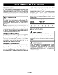
7 - Français CARACTÉRISTIQUES ÉLECTRIQUES DOUBLE ISOLATION La double isolation est un dispositif de sécurité utilisé sur les outils à moteur électriques, éliminant le besoin de cordon d’alimentation habituel à trois fils avec terre. Toutes les pièces métalliques exposées sont isolées des composants ...
Page 37 - GLOSSAIRE
8 - Français GLOSSAIRE Trou pilote (perceuses à colonne et scie à découper) Petit trou pratiqué dans une pièce servant de guide pour assurer la précision d’un trou de plus grand diamètre ou pour l’insertion d’une lame de scie à découper. Blocs poussoirs (pour dégauchisseuses/raboteuses) Dispositifs ...
Page 38 - CARACTÉRISTIQUES; FICHE TECHNIQUE
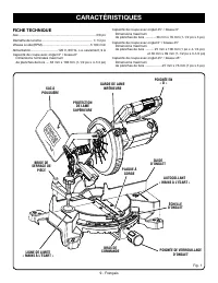
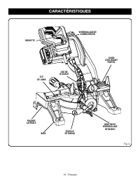
9 - Français BRIDE DE SERRAGE DE PIÈCE CARACTÉRISTIQUES Fig. 1 FICHE TECHNIQUE Axe .......................................................................................5/8 po Diamètre de la lame ......................................................... 7-1/4 po Vitesse à vide (RPM) ..................
Page 40 - BOUTON DE VERROUILLAGE DE BISEAU; GUIDE D’ONGLET
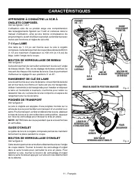
11 - Français BRAS BLOQUÉ EN POSITION ABAISSÉE APPRENDRE À CONNAÎTRE LA SCIE À ONGLETS COMPOSÉS. Voir les figures 1 et 2. L’utilisation sûre de ce produit exige une compréhension des renseignements figurant sur l’outil et contenus dans le manuel d’utilisation, ainsi qu’une bonne connaissance du proj...
Page 41 - GUIDE COULISSANT PARTIEL; BUTÉES POSITIVES DE LA TABLE À ONGLETS; BOUTON DE VERROUILLAGE DE BROCHE; GÂCHETTE
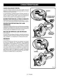
12 - Français GUIDE COULISSANT PARTIEL Le guide coulissant partiel de votre scie à onglets mixte est présent pour aider à sécuriser la pièce à travailler au moment d’effectuer des coupes droites.La caractéristique coulissante permet d’ajuster aisément la position du guide partiel. Desserrer la vis d...
Page 43 - DÉBALLAGE; ASSEMBLAGE
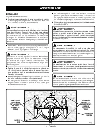
14 - Français La scie est réglée en usine pour effectuer une coupe précise. Après l’avoir assemblée, vérifier sa précision. Si les réglages ont été modifiés en cours d’expédition, voir les procédures spécifiques présentées dans ce manuel. Si des pièces sont manquantes ou endommagées, appeler le...
Page 44 - TROUS DE FIXATION; BOUTON DE VERROUILLAGE D’ONGLET
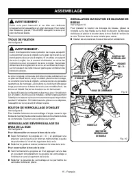
15 - Français AVERTISSEMENT : Cette scie peut basculer si sa tête est relâchée brusquement et assujettie à un plan de travail. Pour éviter des blessures graves, TOUJOURS assujettir la scie à un plan de travail stable. TROUS DE FIXATION Voir la figure 8. AVERTISSEMENT : Avant d’entreprendre toute op...
Page 45 - SAC À POUSSIÈRE; BRIDE DE SERRAGE DE PIÈCE; INSTALLATION / REMPLACEMENT DE LA LAME
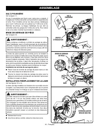
16 - Français tooltip Fig. 12 SAC À POUSSIÈRE Voir la figure 11. Un sac à poussières est fourni avec cette scie à onglets. Il s’adapte sur l’orifice de sortie sur la protection supérieure de la lame. Pour l’installer, pincer les deux pinces métalliques pour ouvrir l’orifice du sac et le glisser sur ...
Page 50 - UTILISATION
21 - Français AVERTISSEMENT : Ne pas laisser la familiarité avec l’outil faire oublier la prudence. Ne pas oublier qu’une fraction de seconde d’inattention peut entraîner des blessures graves. AVERTISSEMENT : Toujours porter une protection oculaire avec écrans latéraux certifiée conforme à la norme ...
Page 52 - POUR COUPE EN BISEAU
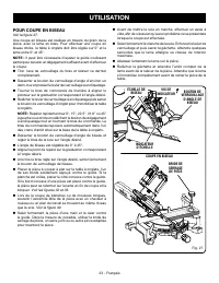
23 - Français COUPE EN BISEAU POUR COUPE EN BISEAU Voir la figure 27. Une coupe en biseau est réalisée en travers du grain de la pièce, avec la lame en biais. Pour effectuer une coupe en biseau droite, la table à onglets doit être réglée sur 0° et la lame entre 0° et 45°. NOTE : Il peut être nécessa...
Page 53 - COUPE D’ONGLET COMPOSÉ
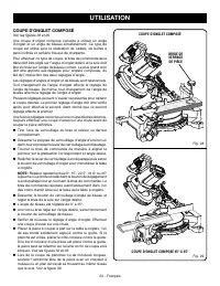
24 - Français Fig. 29 COUPE D’ONGLET COMPOSÉ Voir les figures 28 et 29. Une coupe d’onglet composé consiste à utiliser un angle d’onglet et un angle de biseau simultanément. Ce type de coupe est utilisé pour la réalisation de cadres, de boîtes à pans inclinés et certains travaux de charpente. Pour e...
Page 54 - SUPPORT DE PIÈCES LONGUES; PIÈCE
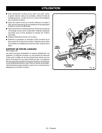
25 - Français Saisir fermement la pièce d’une main et la caler contre le guide. Dans la mesure du possible, utiliser la bride de serrage de pièce, un serre-joint ou ou autre pince adaptée pour maintenir la pièce. Avant de mettre la scie en marche, effectuer un essai à vide, afin de ...
Page 55 - COUPE D’ONGLETS COMPOSÉS; ANGLE
26 - Français UTILISATION COUPE D’ONGLETS COMPOSÉS Le tableau des réglages d’angles ci-dessous est conçu pour faciliter les réglages. Les coupes composées étant les plus difficiles à réaliser, des essais doivent être effectués sur des chutes et la coupe définitive ne doit être effectuée qu’après mûr...
Page 56 - COUPE DE MOULURE COURONNÉE
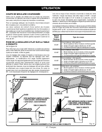
27 - Français PLAFOND M U R 38 ° 52 ° COIN INTÉRIEUR MOULURE COURONNÉE À PLAT SUR LA TABLE À ONGLETS GUIDE TABLE À ONGLETS CÔTÉ INFÉRIEUR CONTRE LE GUIDE = • CÔTÉ DROIT, COIN INTÉRIEUR • CÔTÉ GAUCHE, COIN EXTÉRIEUR GUIDE TABLE À ONGLETS Fig. 31 COIN EXTÉRIEUR CÔTÉ SUPÉRIEUR CONTRE LE GUIDE = • CÔTÉ ...
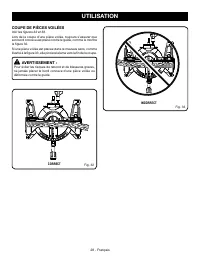
Page 57 - COUPE DE PIÈCES VOILÉES; CORRECT
28 - Français COUPE DE PIÈCES VOILÉES Voir les figures 32 et 33. Lors de la coupe d’une pièce voilée, toujours s’assurer que son bord convexe est placé contre le guide, comme le montre la figure 32.Si une pièce voilée est placée dans le mauvais sens, comme illustré à la figure 33, elle pincera la la...
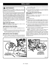
Page 58 - RÉGLAGES DES PIVOTS; RÉGLAGES
29 - Français AVERTISSEMENT : Avant d’effectuer tout réglage, s’assurer que l’outil est débranché. Le non respect de cet avertissement pourrait entraîner des blessures graves. La scie à onglets composés a été réglée en usine pour effectuer des coupes très précises. Toutefois, certains compos...
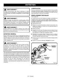
Page 59 - ENTRETIEN GÉNÉRAL; ENTRETIEN; LUBRIFICATION
30 - Français AVERTISSEMENT : Utiliser exclusivement des pièces identiques à celles d’origine pour les réparations. L’usage de toute autre pièce pourrait créer une situation dangereuse ou endommager l’outil. AVERTISSEMENT : Toujours porter une protection oculaire avec écrans latéraux certifiée con...
Page 60 - REGLAS DE SEGURIDAD GENERALES; ÁREA DE TRABAJO; SEGURIDAD ELÉCTRICA
2 - Español REGLAS DE SEGURIDAD GENERALES ADVERTENCIA: Lea todas las advertencias, instrucciones, ilustraciones y e s p e c i f i c a c i o n e s p ro p o rc i o n a d a s c o n e s t a herramienta eléctrica. No seguir las instrucciones indicadas a continuación puede provocar descargas eléctricas, i...
Page 61 - SERVICIO
3 - Español REGLAS DE SEGURIDAD GENERALES REGLAS DE SEGURIDAD SIERRA INGLETEADORA el trabajo, si además se maneja a la velocidad para la que está diseñada. No utilice la herramienta si el interruptor no enciende o no apaga. Cualquier herramienta eléctrica que no pueda controlarse con el interrupto...
Page 62 - ADVERTENCIAS DE SEGURIDAD ADICIONALES
4 - Español firme antes de usarla. Una superficie de trabajo nivelada y firme reduce el riesgo de que la sierra ingleteadora pierda estabilidad. P l a n i f i q u e s u t r a b a j o . C a d a v e z q u e c a m b i e l a configuración del ángulo del bisel o el inglete, asegúrese de que la guía aju...
Page 64 - SÍMBOLOS
6 - Español Es posible que se empleen en esta herramienta algunos de los siguientes símbolos. Le suplicamos estudiarlos y aprender su significado. Una correcta interpretación de estos símbolos le permitirá utilizar mejor y de manera más segura la herramienta. SÍMBOLO NOMBRE DENOMINACIÓN/EXPLICACIÓN ...
Page 65 - ASPECTOS ELÉCTRICOS; DOBLE AISLAMIENTO; CONEXIÓN ELÉCTRICA; CORDONES DE EXTENSIÓN; Longitud
7 - Español ASPECTOS ELÉCTRICOS DOBLE AISLAMIENTO El doble aislamiento es una característica de seguridad de las herramientas eléctricas, la cual elimina la necesidad de usar el típico cordón eléctrico de tres conductores con conexión a tierra. Todas las partes metálicas expuestas están aisladas de ...
Page 66 - GLOSARIO DE TÉRMINOS
8 - Español GLOSARIO DE TÉRMINOS Este es un corte en el cual la hoja no corta la pieza de trabajo en dos pedazos. Agujero guía (taladradoras de columna y sierras caladoras) Es un agujero pequeño taladrado en una pieza de trabajo, el cual sirve como guía para taladrar con precisión agujeros más grand...
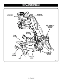
Page 67 - CARACTERÍSTICAS; ESPECIFICACIONES DEL PRODUCTO
9 - Español CARACTERÍSTICAS Fig. 1 ESPECIFICACIONES DEL PRODUCTO Árbol ........................................................................... 5/8 pulg. Diámetro de la hoja ................................................. 7-1/4 pulg.Velocidad en vacío (RPM) ........................................
Page 69 - PERILLA DE FIJACIÓN DE BISEL; GUÍA DE INGLETES
11 - Español FAMILÍCESE CON LA SIERRA INGLETEADORA COMBINADA Vea las figuras 1 y 2. El uso seguro que este producto requiere la comprensión de la información impresa en la herramienta y en el manual del operador así como ciertos conocimientos sobre el proyecto a realizar. Antes de usar este producto...
Page 71 - LISTA DE PIEZAS SUELTAS; HERRAMIENTAS NECESARIAS
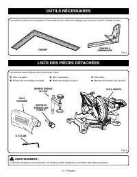
13 - Español LISTA DE PIEZAS SUELTAS Fig. 7 ADVERTENCIA: El empleo de aditamentos o accesorios no enumerados arriba podría ser peligros y causar lesiones serias. Vienen incluidos los siguientes artículos con la herramienta: Sierra ingleteadora Perilla de fijación de inglete Saco captapolvo P...
Page 72 - DESEMPAQUETADO; ARMADO
14 - Español La sierra viene ajustada desde la fábrica para realizar cortes exactos. Después de armarla verifique la exactitud de la misma. Si en el envío resultaron afectados los ajustes, consulte los procedimientos específicos explicados más adelante en este manual. Si hay piezas dañadas o fal...
Page 74 - SACO CAPTAPOLVO; PARA INSTALAR O REEMPLAZAR LA HOJA
16 - Español tooltip Fig. 12 SACO CAPTAPOLVO Vea la figura 11. Se suministra un saco captapolvo para utilizarse con la sierra ingleteadora. Se acopla en la abertura de salida del aserrín, en la protección superior de la hoja. Para instalarlo, apriete los dos clips metálicos para abrir la boca del sa...
Page 76 - ESCUADRADO DE LA HOJA CON LA GUÍA
18 - Español MESA DE INGLETES ESCUADRA GUÍA DE INGLETES HOJA PLACA DE LA GARGANTA EXTRACCIÓN/REEMPLAZO DE LA PLACA DE GARGANTA Vea la figura 15. ADVERTENCIA: La placa de la garganta debe estar a debajo de la mesa de ingletes. Si la placa de la garganta está demasiado alta o demasiado baja, la pieza ...
Page 78 - ESCUADRADO DE LA HOJA CON LA MESA
20 - Español MESA DE INGLETES HOJA ARMADO ESCUADRADO DE LA HOJA CON LA MESA DE INGLETES Vea las figuras 22 a 24. Desconecte la sierra. Tire del brazo de la sierra completamente hacia abajo y enganche el pasador de seguridad para asegurar el brazo en la posición de traslado. Afloje la perilla d...
Page 79 - APLICACIONES; FUNCIONAMIENTO
21 - Español ADVERTENCIA: Para evitar lesiones corporales serias, siempre asegurar la perilla de fijación de inglete y perilla de fijación de bisel antes de efectuar un corte. De lo contrario podría producirse un movimiento del brazo de control o de la mesa de ingletes mientras se efectúa el corte. ...
Page 80 - PARA REALIZAR CORTES DE INGLETE/
22 - Español FUNCIONAMIENTO PARA REALIZAR CORTES DE INGLETE/ TRANSVERSALES Vea las figuras 25 y 26. Los cortes transversales se efectúan cortando a través de la veta de la pieza de trabajo. Un corte transversal recto se efectúa con la mesa de ingletes ajustada en la posición de 0°. Los cortes de ing...
Page 81 - PARA CORTAR A BISEL
23 - Español CORTE EN BISEL PARA CORTAR A BISEL Vea la figura 27. Un corte en bisel se efectúa cortando a través de la fibra de la pieza de trabajo con la hoja en ángulo con dicha pieza. Un corte en bisel recto se efectúa con la mesa de ingletes en la posición de cero grados y la hoja a un ángulo en...
Page 82 - CORTE EN BISEL COMBINADO
24 - Español PARA EFECTUAR UN CORTE A INGLETE COMBINADO Vea las figuras 28 y 29. Un corte en bisel combinado es un corte efectuado a un ángulo de inglete y a un ángulo de bisel al mismo tiempo. Este tipo de corte se usa para elaborar marcos de cuadros, cortar molduras, elaborar cajas con lados incli...
Page 83 - PARA APOYAR LAS PIEZAS DE TRABAJO; PIEZA DE
25 - Español Al cortar tablas o molduras largas, apoye el extremo opuesto del material sobre un soporte de rodillo o con una superficie de trabajo a nivel con la mesa de la sierra. Vea la figura 30. Sujete firmemente la pieza con una mano y asegúrela contra la guía. Use la prensa de trabajo, pre...
Page 84 - CÓMO EFECTUAR CORTES A INGLETE COMBINADOS; INCLINACIÓN
26 - Español FUNCIONAMIENTO CÓMO EFECTUAR CORTES A INGLETE COMBINADOS Como ayuda para realizar los ajustes correctos, se suministra la siguiente tabla de ángulos combinados. Puesto que los cortes combinados son los más difíciles de obtener, deben efectuarse cortes de prueba en material de desecho, a...
Page 85 - CÓMO CORTAR MOLDURAS DE CORONA
27 - Español Al cortar molduras de corona con este método, el ángulo de bisel debe fijarse a 33,85°. El ángulo de inglete debe fijarse a 31,62°, a la derecha o izquierda, según el corte deseado para cada aplicación en particular. En la tabla mostrada abajo encontrará los ajustes correctos de los áng...
Page 86 - CÓMO CORTAR MATERIAL TORCIDO; FORMA CORRECTA
28 - Español CÓMO CORTAR MATERIAL TORCIDO Vea las figuras 32 y 33. Al cortar material torcido, asegúrese siempre de que esté situado sobre la mesa de ingletes con el canto convexo apoyado contra la guía, como se muestra en la figura 32.Si se coloca de forma incorrecta como se muestra en la figura 33...
Page 87 - AJUSTES; AJUSTES DE LOS PIVOTES
29 - Español AJUSTES ADVERTENCIA: Antes de efectuar cualquier ajuste, asegúrese de que la herramienta esté desconectada del suministro de corriente. La inobservancia de esta advertencia podría causar lesiones corporales serias. La sierra ingleteadora combinada ha sido ajustada en la fábrica para pro...
Page 88 - MANTENIMIENTO; MANTENIMIENTO GENERAL
30 - Español MANTENIMIENTO ADVERTENCIA: Al dar servicio a la unidad, utilice sólo piezas de repuesto idénticas. El empleo de piezas diferentes puede presentar un peligro o causar daños al producto. ADVERTENCIA: Siempre póngase protección ocular con la marca de cumplimiento de la norma ANSI Z87.1. Si...
Page 92 - OPERATOR’S MANUAL / COMPOUND MITER SAW
9950006921-25-19 (REV:02) OPERATOR’S MANUAL / COMPOUND MITER SAW MANUEL D’UTILISATION / SCIE À ONGLETS COMBINÉSMANUAL DEL OPERADOR / SIERRA INGLETEADORA COMPUESTA TS1144 ONE WORLD TECHNOLOGIES, INC. 1428 Pearman Dairy Road, Anderson, SC 29625 • Phone 1-800-525-2579 États-Unis, Téléphone 1-800-525-25...