Page 2 - GENERAL SAFETY RULES; Save all warnings and instructions for future reference.; WORK AREA SAFETY; Keep work area clean and well lit.; ELECTRICAL SAFETY; Do not expose power tools to rain or wet conditions.; PERSONAL SAFETY
2 — English GENERAL SAFETY RULES WARNING: Read all safety warnings, instructions, illustrations and specifications provided with this power tool. Failure to follow all instructions listed below may result in electric shock, fire and/or serious injury. Save all warnings and instructions for future re...
Page 3 - the workpiece into the blade or cut ”freehand” in any; Cut only one workpiece at a time.; Keep cutting tools sharp and clean.; SERVICE
3 — English GENERAL SAFETY RULES MITER SAW SPECIFIC SAFETY RULES Miter saws are intended to cut wood or wood-like products, they cannot be used with abrasive cut-off wheels for cutting ferrous material such as bars, rods, studs, etc. Abrasive dust causes moving parts such as the lower guard to jam...
Page 4 - MITER SAW SPECIFIC SAFETY RULES; ADDITIONAL SAFETY RULES
4 — English MITER SAW SPECIFIC SAFETY RULES Provide adequate support such as table extensions, saw horses, etc. for a workpiece that is wider or longer than the table top. Workpieces longer or wider than the miter saw table can tip if not securely supported. If the cut-off piece or workpiece tips,...
Page 6 - SYMBOLS
6 — English The following signal words and meanings are intended to explain the levels of risk associated with this product. SYMBOL SIGNAL MEANING DANGER: Indicates a hazardous situation, which, if not avoided, will result in death or serious injury. WARNING: Indicates a hazardous situation, which, ...
Page 7 - ELECTRICAL; DOUBLE INSULATION; ELECTRICAL CONNECTION; power supply that is 120 V, AC only (normal; EXTENSION CORDS; Cord Length
7 — English ELECTRICAL DOUBLE INSULATION Double insulation is a concept in safety in electric power tools, which eliminates the need for the usual three-wire grounded power cord. All exposed metal parts are isolated from the internal metal motor components with protecting insulation. Double insulate...
Page 8 - GLOSSARY OF TERMS
8 — English GLOSSARY OF TERMS Pilot Hole (drill presses and scroll saws) A small hole drilled in a workpiece that serves as a guide for drilling large holes accurately or for insertion of a scroll saw blade. Push Blocks (jointer planers) Device used to feed the workpiece over the jointer planer cutt...
Page 9 - FEATURES; PRODUCT SPECIFICATIONS
9 — English FEATURES PRODUCT SPECIFICATIONS Blade Arbor ............................................................... 5/8 in.Blade Diameter ............................................................10 in.No Load Speed .......................................5,500 /min. (RPM)Input ...................
Page 10 - “D” HANDLE; BEVEL
10 — English FEATURES KNOW YOUR COMPOUND MITER SAW See Figure 1. The safe use of this product requires an understanding of the information on the tool and in this operator’s manual as well as a knowledge of the project you are attempting. Before use of this product, familiarize yourself with all ope...
Page 11 - PARTIAL SLIDING FENCE; OFF
11 — English SPINDLE LOCK BUTTON PADLOCK SWITCH TRIGGER Fig. 4 FEATURES PARTIAL SLIDING FENCE The partial sliding fence on your compound miter saw has been provided to help secure the workpiece when making straight cuts.The sliding feature makes it easy to adjust the position of the partial fence. L...
Page 13 - ASSEMBLY; UNPACKING
13 — English ASSEMBLY Fig. 7 MOUNTING SURFACE BASE TRACE HOLES AT THESE LOCATIONS FOR HOLE PATTERN TRACE HOLES AT THESE LOCATIONS FOR HOLE PATTERN WARNING: If any parts are damaged or missing do not operate this tool until the parts are replaced. Use of this product with damaged or missing parts cou...
Page 14 - MOUNTING HOLES; To unlock and raise the saw arm:; DUST BAG
14 — English ASSEMBLY Fig. 8 Fig. 9 TO LOOSEN MITER LOCK HANDLE TO TIGHTEN MOUNTING HOLES See Figure 7. WARNING: Before starting any cutting operation, clamp or bolt your miter saw to a workbench or an approved miter saw stand. If a miter saw stand is used, read operator’s manual and follow the inst...
Page 15 - BLADE WRENCH; To install the work clamp:; TO INSTALL/REPLACE THE BLADE
15 — English Fig. 11 ASSEMBLY Fig. 12 WORK CLAMP BASE BLADE WRENCH BLADE WRENCH See Figure 11. A blade wrench is included with this saw. One end of the wrench is a Phillips screwdriver and the other end is a hex key. Use the hex key end when installing or removing blade and the Phillips end when rem...
Page 16 - Do not
16 — English ASSEMBLY Using the Phillips screwdriver end of the blade wrench, loosen, but do not remove, the blade bolt cover screw. Rotate lower blade guard and blade bolt cover up and back to expose the blade bolt. Depress and hold the spindle lock button and rotate the blade bolt until the sp...
Page 17 - SQUARING THE SAW BLADE TO THE FENCE
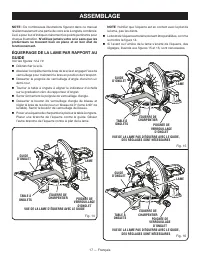
17 — English ASSEMBLY NOTE: Many of the illustrations in this manual show only portions of the compound miter saw. This is intentional so that we can clearly show points being made in the illustrations. Never operate the saw without all guards securely in place and in good operating condition. SQUAR...
Page 19 - SQUARING THE BLADE TO THE MITER TABLE; Positive Stop
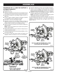
19 — English Fig. 20 CORRECT VIEW OF BLADE SQUARE WITH MITER TABLE MITER TABLE MITER TABLE MITER TABLE MITER LOCK HANDLE COMBINATION SQUARE COMBINATION SQUARE COMBINATION SQUARE BLADE BLADE BLADE BEVEL LOCK KNOB POSITIVE STOP ADJUSTMENT SCREWS ASSEMBLY SQUARING THE BLADE TO THE MITER TABLE See Figur...
Page 20 - OPERATION; APPLICATIONS; LED LIGHTING SYSTEM
20 — English OPERATION WARNING: Do not allow familiarity with tools to make you careless. Remember that a careless fraction of a second is sufficient to inflict serious injury. WARNING: Always wear eye protection with side shields marked to comply with ANSI Z87.1. Failure to do so could result in ob...
Page 21 - TO MITER CUT/CROSS CUT
21 — English OPERATION WORK CLAMP CROSS CUT MITER CUT Fig. 24 Fig. 25 TO MITER CUT/CROSS CUT See Figures 24 - 25. A cross cut is made by cutting across the grain of the workpiece. A straight cross cut is made with the miter table set at the 0 ° position. Miter cross cuts are made with the miter tabl...
Page 22 - TO BEVEL CUT
22 — English OPERATION Before turning on the saw, perform a dry run of the cutting operation just to make sure that no problems will occur when the cut is made. Grasp the saw handle firmly. Depress the trigger lockout lever and squeeze the switch trigger. Allow several seconds for the blade to r...
Page 23 - TO COMPOUND MITER CUT; WORK CLAMP
23 — English OPERATION TO COMPOUND MITER CUT See Figures 28 - 29. A compound miter cut is a cut made using a miter angle and a bevel angle at the same time. This type of cut is used to make picture frames, cut molding, make boxes with sloping sides, and for certain roof framing cuts. To make this ty...
Page 24 - TO SUPPORT LONG WORKPIECES; LONG
24 — English OPERATION Grasp the stock firmly with one hand and secure it against the fence. Use the work clamp, C-clamp, or other suitable clamp to secure the workpiece when possible. Before turning on the saw, perform a dry run of the cutting operation just to make sure that no problems will o...
Page 25 - CUTTING COMPOUND MITERS; PITCH
25 — English OPERATION CUTTING COMPOUND MITERS To aid in making the correct settings, the compound angle setting chart below has been provided. Since compound cuts are the most difficult to accurately obtain, trial cuts should be made in scrap material, and much thought and planning made, prior to m...
Page 26 - CUTTING CROWN MOLDING; LAYING MOLDING FLAT ON THE MITER TABLE
26 — English OPERATION 31.6° either right or left, depending on the desired cut for the application. See the chart below for correct angle settings and correct positioning of crown molding on miter table.The settings in the chart on page 24 can be used for cutting All Standard (U.S.) crown molding w...
Page 27 - CUTTING WARPED MATERIAL; RIGHT
27 — English OPERATION CUTTING WARPED MATERIAL See Figures 32 - 33. When cutting warped material, always make sure it is positioned on the miter table with the convex side against the fence as shown in figure 32.If the warped material is positioned the wrong way as shown in figure 33, it will pinch ...
Page 28 - ADJUSTMENTS; PIVOT ADJUSTMENTS; RYOBI; BEVEL PIVOT ADJUSTMENT; RYOBI AUTHORIZED SERVICE; DEPTH STOP
28 — English ADJUSTMENTS WARNING: Before performing any adjustment, make sure the tool is unplugged from the power supply. Failure to heed this warning could result in serious personal injury. The compound miter saw has been adjusted at the factory for making accurate cuts. However, some of the comp...
Page 29 - MAINTENANCE; GENERAL MAINTENANCE; Proceed as follows when replacement is required:
29 — English MAINTENANCE WARNING: When servicing, use only identical replacement parts. Use of any other parts can create a hazard or cause product damage. WARNING: Always wear eye protection with side shields marked to comply with ANSI Z87.1. Failure to do so could result in objects being thrown in...
Page 30 - CLEANING THE LED LENS; LED
30 — English MAINTENANCE CLEANING THE LED LENS See Figure 37. Over time the LED light may become cloudy or dull. If this occurs, the LED lens may require cleaning. To clean the lens: Unplug the saw. Raise the saw arm. Fig. 37 Remove the blade as described in the Assembly section. Rotate the ...
Page 31 - SÉCURITÉ DU LIEU DE TRAVAIL; Garder le lieu de travail propre et bien éclairé.; SÉCURITÉ ÉLECTRIQUE; RÈGLES DE SÉCURITÉ GÉNÉRALES; SÉCURITÉ PERSONNELLE
2 — Français AVERTISSEMENT : Lire les avertissements de sécurité, les instructions et les précisions et consulter les illustrations fournis avec cet outil électrique. Le fait de ne pas se conformer à l’ensemble des consignes présentées ci-dessous risque d’entraîner des décharges électriques, un ince...
Page 32 - Garder les outils bien affûtés et propres.; DÉPANNAGE; RÈGLES DE SÉCURITÉ DU SCIE À ONLGETS; Couper une seule pièce à travailler à la fois.
3 — Français RÈGLES DE SÉCURITÉ GÉNÉRALES Avant de procéder à un réglage, à un changement d’accessoire ou au rangement de l’outil, débranchez la prise de la source d’alimentation ou, si le bloc-piles est amovible, retirez-le de l’outil. Ces mesures de sécurité préventives réduisent les risques de ...
Page 33 - Conserver ces instructions.; RÈGLES DE SÉCURITÉ SUPLÉMENTAIRES; Utiliser un cordon prolongateur adéquat.
4 — Français RÈGLES DE SÉCURITÉ DU SCIE À ONLGETS S’assurer que la scie à onglets est montée ou placée à niveau sur une surface de travail ferme avant de l’utiliser. Une surface de travail ferme et à niveau réduit le risque que la scie à onglets devienne instable. Planifier votre travail. Chaque...
Page 35 - SYMBOLES; SYMBOLE
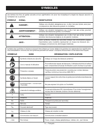
6 — Français SYMBOLES Les termes de mise en garde suivants et leur signification ont pour but d’expliquer le degré de risques associé à l’utilisation de ce produit. SYMBOLE SIGNAL SIGNIFICATION DANGER : Indique une situation dangereuse qui, si elle n’est pas évitée, aura pour conséquences des blessu...
Page 36 - CARACTÉRISTIQUES ÉLECTRIQUES; DOUBLE ISOLATION; CONNEXIONS ÉLECTRIQUES; une alimentation 120 V,; CORDONS PROLONGATEURS; Longueur
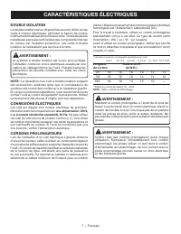
7 — Français CARACTÉRISTIQUES ÉLECTRIQUES DOUBLE ISOLATION La double isolation est un dispositif de sécurité utilisé sur les outils à moteur électriques, éliminant le besoin de cordon d’alimentation habituel à trois fils avec terre. Toutes les pièces métalliques exposées sont isolées des composants ...
Page 37 - GLOSSAIRE
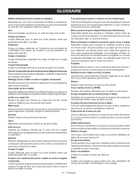
8 — Français GLOSSAIRE Trou pilote (perceuses à colonne et scie à découper) Petit trou pratiqué dans une pièce servant de guide pour assurer la précision d’un trou de plus grand diamètre ou pour l’insertion d’une lame de scie à découper. Blocs poussoirs (pour dégauchisseuses/raboteuses) Dispositifs ...
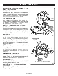
Page 38 - CARACTÉRISTIQUES
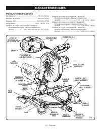
9 — Français CARACTÉRISTIQUES PRODUCT SPECIFICATIONS Axe de lame ...................................................... 16 mm (5/8 po) Diamètre de la lame......................................... 254 mm (10 po)Vitesse à vide ................................................ 5 500 /min (RPM) Alimentat...
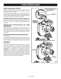
Page 40 - GUIDE COULISSANT PARTIEL; BUTÉES POSITIVES DE LA TABLE À ONGLETS; BOUTON DE VERROUILLAGE DE BROCHE; GÂCHETTE; ARRÊT
11 — Français CADENAS GÂCHETTE GUIDE COULISSANT PARTIEL Le guide coulissant partiel de votre scie à onglets mixte est présent pour aider à sécuriser la pièce à travailler au moment d’effectuer des coupes droites.La caractéristique coulissante permet d’ajuster aisément la position du guide partiel. D...
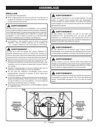
Page 42 - ASSEMBLAGE; DÉBALLAGE
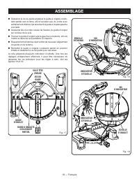
13 — Français ASSEMBLAGE Fig. 7 SURFACE DE FIXATION BASE AVERTISSEMENT : Si des pièces manquent ou sont endommagées, ne pas utiliser ce produit avant qu’elles aient été remplacées. Le fait d’utiliser ce produit même s’il contient des pièces endommagées ou s’il lui manque des pièces peut entraîner de...
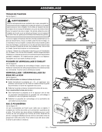
Page 43 - TROUS DE FIXATION; POIGNÉE DE VERROUILLAGE D’ONGLET; SAC À POUSSIÈRES
14 — Français TROUS DE FIXATION Voir la figure 7. AVERTISSEMENT : Avant d’entreprendre toute opération de coupe, assujettir ou boulonner la scie à onglets sur le plan de travail ou un stand approuvé pour scie à onglets. Si on utilise un support de scie à onglet, lire le manuel d’utilisation et suiv...
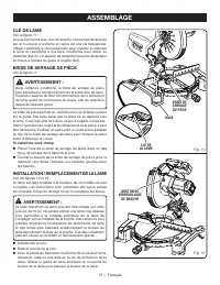
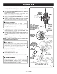
Page 44 - INSTALLATION / REMPLACEMENT DE LA LAME
15 — Français CLÉ DE LA LAME CLÉ DE LAME Voir la figure 11. La scie est fournie avec une clé de lame. Une extrémité de la clé est un tournevis cruciforme et l’autre est une clé hexagonale. Utiliser l’extrémité à clé hexagonale pour installer et déposer la lame et l’extrémité à tournevis cruciforme p...
Page 49 - UTILISATION; SYSTÈME D’ÉCLAIRAGE DEL
20 — Français UTILISATION AVERTISSEMENT : Ne pas laisser la familiarité avec l’outil faire oublier la prudence. Ne pas oublier qu’une fraction de seconde d’inattention peut entraîner des blessures graves. AVERTISSEMENT : Toujours porter une protection oculaire certifiée conforme à la norme ANSI Z87....
Page 51 - COUPE EN BISEAU
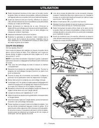
22 — Français Saisir fermement la pièce d’une main et la caler contre le guide. Dans la mesure du possible, utiliser la bride de serrage de pièce ou un serre-joint pour maintenir la pièce. Avant de mettre la scie en marche, effectuer un essai à vide, afin de s’assurer qu’aucun problème ne se ...
Page 52 - COUPE D’ONGLET COMPOSÉ; BRIDE DE
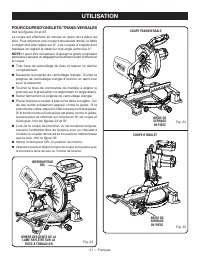
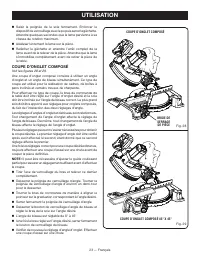
23 — Français Saisir la poignée de la scie fermement. Enfoncer le dispositif de verrouillage avec le po puis serrer la gâchette. Attendre quelques secondes que la lame parvienne à sa vitesse de rotation maximum. Abaisser lentement la lame sur la pièce. Relâcher la gâchette ...
Page 53 - SUPPORT DE PIÈCES LONGUES; PIÈCE
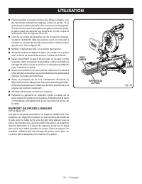
24 — Français Placer la pièce à couper à plat sur la table à onglets, l’un de ses bords solidement appuyé contre le guide. Si la planche est voilée, placer le côté convexe contre le guide. Si le bord concave d’une pièce est placé contre le guide, la pièce peut se refermer sur la lame en fin de cou...
Page 54 - COUPE D’ONGLETS COMPOSÉS; ANGLE
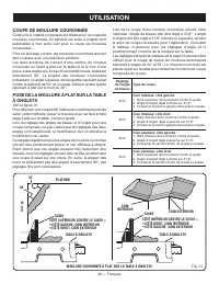
25 — Français COUPE D’ONGLETS COMPOSÉS Le tableau des réglages d’angles ci-dessous est conçu pour faciliter les réglages. Les coupes composées étant les plus difficiles à réaliser, des essais doivent être effectués sur des chutes et la coupe définitive ne doit être effectuée qu’après mûre réflexion ...
Page 55 - COUPE DE MOULURE COURONNÉE
26 — Français Lors de la coupe d’une moulure couronnée suivant cette méthode, l’angle de biseau doit être réglé à 33,9°. L’angle d’onglet doit être réglé à 31,6° à droite ou à gauche, suivant le sens de coupe nécessaire pour l’application. Consulter le tableau ci-dessous pour les réglages d’angle et...
Page 56 - CORRECT
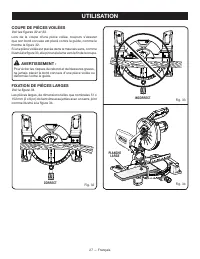
27 — Français COUPE DE PIÈCES VOILÉES Voir les figures 32 et 33. Lors de la coupe d’une pièce voilée, toujours s’assurer que son bord convexe est placé contre le guide, comme le montre la figure 32.Si une pièce voilée est placée dans le mauvais sens, comme illustré à la figure 33, elle pincera la la...
Page 57 - CENTRE DE RÉPARATIONS AGRÉÉ RYOBI; RÉGLAGE DU PIVOT DE BISEAU; CENTRE; BUTÉE DE PROFONDEUR; ENTRETIEN
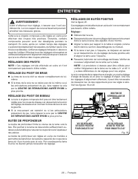
28 — Français AVERTISSEMENT : Avant d’effectuer tout réglage, s’assurer que l’outil est débranché. Le non respect de cet avertissement pourrait entraîner des blessures graves. Cette scie à onglets composés a été réglée en usine pour effectuer des coupes très précises. Toutefois, certains com...
Page 58 - RÉGLAGES; ENTRETIEN GÉNÉRAL
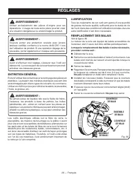
29 — Français RÉGLAGES AVERTISSEMENT : Utiliser exclusivement des pièces d’origine pour les réparations. L’usage de toute autre pièce pourrait créer une situation dangereuse ou endommager le produit. AVERTISSEMENT : Toujours porter une protection oculaire avec écrans latéraux certifiée conforme à...
Page 59 - NETTOYAGE DE LA LENTILLE DEL; Pour nettoyer la lentille :; LENTILLE
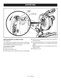
30 — Français ENTRETIEN NETTOYAGE DE LA LENTILLE DEL Voir la figure 37. Avec le temps, il est possible que la lumière à la DEL devi - enne embrouillée ou diffuse. Si c’est le cas, il est possible que la lentille à la DEL doive être nettoyée. Pour nettoyer la lentille : Débrancher la scie. Soulev...
Page 60 - REGLAS DE SEGURIDAD GENERALES; ÁREA DE TRABAJO; Mantenga limpia y bien iluminada el área de trabajo.; SEGURIDAD ELÉCTRICA
2 — Español REGLAS DE SEGURIDAD GENERALES ADVERTENCIA: L e a t o d a s l a s a d v e r t e n c i a s , i n s t r u c c i o n e s , ilustraciones y especificaciones proporcionadas con esta herramienta eléctrica. No seguir las instrucciones indicadas a continuación puede provocar descargas eléctricas,...
Page 61 - Mantenga las herramientas de corte afiladas y limpias.; SERVICIO; de trabajo hacia la hoja o corte sin usar las manos
3 — Español REGLAS DE SEGURIDAD GENERALES REGLAS DE SEGURIDAD SIERRA INGLETEADORA La herramienta eléctrica adecuada efectúa mejor y de manera más segura el trabajo, si además se maneja a la velocidad para la que está diseñada. No utilice la herramienta si el interruptor no enciende o no apaga. Cua...
Page 62 - REGLAS DE SEGURIDAD SIERRA INGLETEADORA; Corte solo una pieza de trabajo por vez.; Guarde estas instrucciones.; ADVERTENCIAS DE SEGURIDAD ADICIONALES; Use un cordón de extensión adecuado.
4 — Español REGLAS DE SEGURIDAD SIERRA INGLETEADORA Corte solo una pieza de trabajo por vez. Varias piezas de trabajo apiladas no pueden sujetarse de forma adecuada, por lo que podrían quedar atascadas en la hoja o desplazarse durante el corte. Asegúrese de que la sierra ingleteadora esté montad...
Page 64 - SÍMBOLOS; SÍMBOLO
6 — Español SÍMBOLOS Las siguientes palabras de señalización y sus significados tienen el objeto de explicar los niveles de riesgo relaciona-dos con este producto. SÍMBOLO SEÑAL SIGNIFICADO PELIGRO: Indica una situación peligrosa, la cual, si no se evita, causará la muerte o lesiones serias. ADVERTE...
Page 65 - ASPECTOS ELÉCTRICOS; DOBLE AISLAMIENTO; un suministro; CORDONES DE EXTENSIÓN; Longitud
7 — Español ASPECTOS ELÉCTRICOS DOBLE AISLAMIENTO El doble aislamiento es una característica de seguridad de las herramientas eléctricas, la cual elimina la necesidad de usar el típico cordón eléctrico de tres conductores con conexión a tierra. Todas las partes metálicas expuestas están aisladas de ...
Page 66 - GLOSARIO DE TÉRMINOS
8 — Español GLOSARIO DE TÉRMINOS Este es un corte en el cual la hoja no corta la pieza de trabajo en dos pedazos. Agujero guía (taladradoras de columna y sierras caladoras) Es un agujero pequeño taladrado en una pieza de trabajo, el cual sirve como guía para taladrar con precisión agujeros más grand...
Page 67 - CARACTERÍSTICAS; ESPECIFICACIONES DEL PRODUCTO
9 — Español CARACTERÍSTICAS ESPECIFICACIONES DEL PRODUCTO Árbol de la hoja de corte ....................................16 mm (5/8 pulg.) Diámetro de la hoja ........................................... 254 mm (10 pulg.)Velocidad en vacío ............................................. 5 500 /min (RPM)...
Page 68 - FRENO ELÉCTRICO
10 — Español F A M I L I A R Í C E S E C O N L A S I E R R A INGLETEADORA COMPUESTA Vea la figura 1. El uso seguro que este producto requiere la comprensión de la información impresa en la herramienta y en el manual del operador así como ciertos conocimientos sobre el proyecto a realizar. Antes de u...
Page 69 - TOPES DE LA MESA DE INGLETES; APAGADO
11 — Español MANIJA DE FIJACIÓN DE INGLETE Vea la figura 3. La manija de fijación de inglete asegura firmemente la sierra en los ángulos de inglete deseados. GUÍA DE INGLETES DESLIZABLE PARCIAL La guía de ingletes deslizable parcial de su sierra ingleteadora compuesta sirve para ayudarlo a asegurar ...
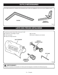
Page 70 - PIEZAS SUELTAS; HERRAMIENTAS NECESARIAS
12 — Español PIEZAS SUELTAS ADVERTENCIA: El empleo de aditamentos o accesorios no enumerados arriba podría ser peligros y causar lesiones serias. Manija de fijación de inglete Saco captapolvo Prensa de trabajo Llave de la hoja Manual del operador (no se muestra) Se necesitan las siguientes...
Page 71 - ARMADO; DESEMPAQUETADO
13 — Español ARMADO Fig. 7 BASE Si hay piezas dañadas o faltantes, le suplicamos llamar al 1-800-525-2579, donde le brindaremos asistencia. ADVERTENCIA: Si hay piezas dañadas o faltantes, no utilice esta herramienta sin haber reemplazado todas las piezas. La inobservancia de esta advertencia podrí...
Page 72 - SACO CAPTAPOLVO
14 — Español AGUJEROS DE MONTAJE Vea la figura 7. ADVERTENCIA: Antes de iniciar cualquier operación de corte, sujete con prensa(s) o atornille la sierra ingleteadora al banco de trabajo o pedestal para sierra ingleteadora aprobado. Si se utiliza un pedestal para sierra ingleteadora, lea el manual de...
Page 73 - PARA INSTALAR O REEMPLAZAR LA HOJA
15 — Español las ranuras de la abertura de salida del aserrín. Para retirar el saco captapolvo con el fin de vaciarlo, invierta el procedimiento anterior. LLAVE DE LA HOJA Vea la figura 11. Esta sierra incluye una llave para la hoja. Un extremo de la llave es un destornillador Phillips y el otro una...
Page 78 - FUNCIONAMIENTO; APLICACIONES
20 — Español FUNCIONAMIENTO ADVERTENCIA: No permita que su familarización con las herramientas lo vuelva descuidado. Tenga presente que un descuido de un instante es suficiente para causar una lesión grave. ADVERTENCIA: Siempre utilice protección para los ojos con escudos laterales que cumplan con A...
Page 80 - PARA CORTAR A BISEL
22 — Español Baje la hoja y alinee la línea de corte de la pieza de trabajo con el borde de la hoja de la sierra o la sombra de la hoja. Sujete firmemente la pieza con una mano y asegúrela contra la guía. Use la prensa de trabajo, prensa en c, u otra prensa adecuada para asegurar la pieza cuando...
Page 81 - PARA CORTAR INGLETES COMPUESTOS; PRENSA DE
23 — Español Sujete firmemente el mango de la sierra. Oprima la palanca del seguro del gatillo y luego oprima el gatillo. Deje transcurrir varios segundos para que la hoja alcance su velocidad máxima. Baje lentamente la hoja de la sierra hacia la pieza de trabajo y corte ésta. Suelte el gatill...
Page 82 - APOYE LAS PIEZAS DE TRABAJO LARGAS
24 — Español Vuelva a revisar el ajuste del ángulo de inglete. Efectúe un corte de prueba en material de desecho. Coloque la pieza de trabajo horizontal en la mesa de ingletes, con un borde firme contra la guía. Si está distorsionada la tabla, coloque el lado convexo contra la guía. Si se el can...
Page 83 - CÓMO EFECTUAR CORTES A INGLETE COMBINADOS; INCLINACIÓN
25 — Español FUNCIONAMIENTO CÓMO EFECTUAR CORTES A INGLETE COMBINADOS Como ayuda para realizar los ajustes correctos, se suministra la siguiente tabla de ángulos combinados. Puesto que los cortes combinados son los más difíciles de obtener, deben efectuarse cortes de prueba en material de desecho, a...
Page 84 - CÓMO CORTAR MOLDURAS DE CORONA
26 — Español Al cortar molduras de corona con este método, el ángulo de bisel debe fijarse a 33,9°. El ángulo de inglete debe fijarse a 31,6°, a la derecha o izquierda, según el corte deseado para cada aplicación en particular. En la tabla mostrada abajo encontrará los ajustes correctos de los ángul...
Page 85 - FORMA CORRECTA; TABLA
27 — Español CÓMO CORTAR MATERIAL DISTORSIONADO Vea las figuras 32 y 33. Al cortar material distorsionado, siempre asegúrese de que esté colocado en la mesa de ingletes con el lado convexo contra la guía, como se muestra en la figura 32.Si se coloca de una forma equivocada el material distorsionado,...
Page 86 - CENTRO DE SERVICIO AUTORIZADO; TOPE DE PROFUNDIDAD; AJUSTES
28 — Español ADVERTENCIA: Antes de efectuar cualquier ajuste, asegúrese de que la herramienta esté desconectada del suministro de corriente. La inobservancia de esta advertencia podría causar lesiones corporales serias. La sierra ingleteadora combinada ha sido ajustada en la fábrica para producir co...
Page 87 - MANTENIMIENTO; MANTENIMIENTO GENERAL; Proceda como sigue cuando se requiera un reemplazo:
29 — Español MANTENIMIENTO ADVERTENCIA: Al dar servicio a la unidad, utilice sólo piezas de repuesto idénticas. El empleo de piezas diferentes puede presentar un peligro o causar daños al producto. ADVERTENCIA: Siempre póngase protección ocular con la marca de cumplimiento de la norma ANSI Z87.1. Si...
Page 88 - LIMPIEZA DE LA LENTE LED; Para limpiar la lente:; LENTE
30 — Español FUNCIONAMIENTO LIMPIEZA DE LA LENTE LED Vea la figura 37. Con el tiempo, es posible que la luz LED se vea opacada o tenue. Si ocurre esto, es posible que la lente LED deba limpiarse. Para limpiar la lente: Desconecte la sierra. Eleve el brazo de la sierra. Vuelve a colocar la hoja...
Page 92 - OPERATOR’S MANUAL/COMPOUND MITER SAW
99500070312-7-18 (REV:02) OPERATOR’S MANUAL/COMPOUND MITER SAW MANUEL D’UTILISATION/SCIE À ONGLETS COMBINÉSMANUAL DEL OPERADOR/SIERRA INGLETEADORA COMPUESTA TS1346/TS1346T ONE WORLD TECHNOLOGIES, INC. P.O. Box 1288, Anderson, SC 29622 • Phone 1-800-525-2579 États-Unis, Téléphone 1-800-525-2579 • USA...