MSI PRO X670-P - Manuals
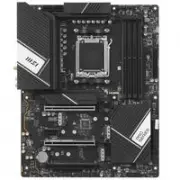
User Manual MSI PRO X670-P
1
2

3
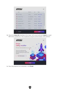
4
5
6
7
8

9
10
11
12
13
14
15
16
17
18
19
20
21
22
23
24
25
26
27
28
29
30
31
32
33
34
35
36
37
38
39
40
41
42
43
44
45
46
47
48
49
50
51
52
53
54
55
56
57
58

59
60
61
62
63
64
Summary
Page 2 - English
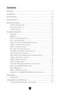
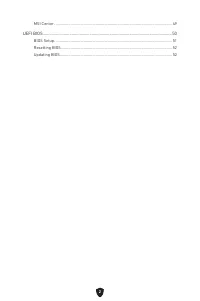
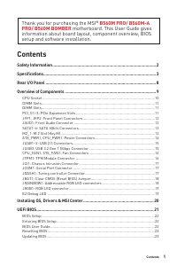
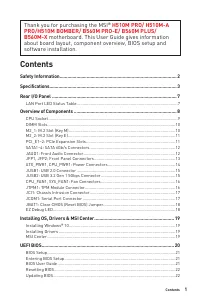
Page 3 - Contents
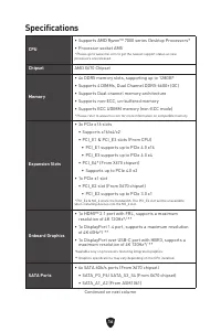
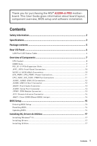
1 Contents Quick Start..................................................................................................................... 3Specifications .............................................................................................................. 16Special Features .................
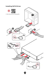
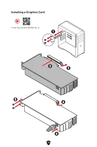
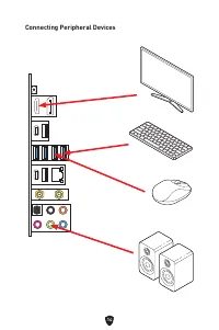
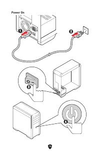
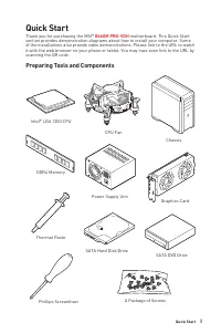
Page 5 - Quick Start; Preparing Tools and Components
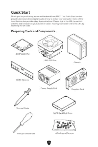
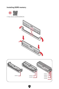
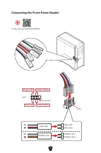
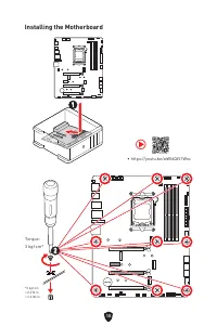
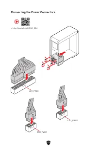
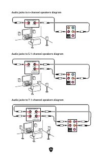
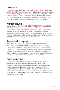
3 Quick Start Thank you for purchasing a new motherboard from MSI®. This Quick Start section provides demonstration diagrams about how to install your computer. Some of the installations also provide video demonstrations. Please link to the URL to watch it with the web browser on your phone or table...
MSI Motherboards Manuals
-
 MSI A320M-A PRO
User Manual
MSI A320M-A PRO
User Manual
-
 MSI A520
User Manual
MSI A520
User Manual
-
 MSI A520M-A PRO
User Manual
MSI A520M-A PRO
User Manual
-
 MSI B450M-A PRO
User Manual
MSI B450M-A PRO
User Manual
-
 MSI B460
User Manual
MSI B460
User Manual
-
 MSI B550-A PRO
User Manual
MSI B550-A PRO
User Manual
-
 MSI B550M PRO-VDH
User Manual
MSI B550M PRO-VDH
User Manual
-
 MSI B560
User Manual
MSI B560
User Manual
-
 MSI B560-A PRO
User Manual
MSI B560-A PRO
User Manual
-
 MSI B560M BOMBER
User Manual
MSI B560M BOMBER
User Manual
-
 MSI B560M PRO-E
User Manual
MSI B560M PRO-E
User Manual
-
 MSI B660
User Manual
MSI B660
User Manual
-
 MSI B660M
User Manual
MSI B660M
User Manual
-
 MSI H510
User Manual
MSI H510
User Manual
-
 MSI H510M-A PRO
User Manual
MSI H510M-A PRO
User Manual
-
 MSI H610
User Manual
MSI H610
User Manual
-
 MSI MAG B550
User Manual
MSI MAG B550
User Manual
-
 MSI MAG B550M
User Manual
MSI MAG B550M
User Manual
-
 MSI MAG B650M
User Manual
MSI MAG B650M
User Manual
-
 MSI MAG Z690
User Manual
MSI MAG Z690
User Manual