Miele PDR 516 SL ROP [EL IGS] - Manuals
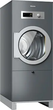
Miele PDR 516 SL ROP [EL IGS] – User Manual, Installation Manual, Quick Guide in PDF format online.
Manuals:
User Manual Miele PDR 516 SL ROP [EL IGS]


Summary
Contents 2 Caring for the environment ........................................................................................................ 4 Warning and Safety instructions ............................................................................................. 5 Appropriate use ..............
Caring for the environment 4 Disposal of the packing material The packaging is designed to protect the appliance from damage dur-ing transportation. The packaging materials used are selected frommaterials which are environmentally friendly for disposal and shouldbe recycled.Recycling the packaging r...
Warning and Safety instructions 5 It is essential to read these instructions. This tumble dryer complies with all current local and national safety requirements. How-ever, inappropriate use can lead to personal injury and damage to property.Read the operating instructions carefully before using th...
Installation Manual Miele PDR 516 SL ROP [EL IGS]


Summary
de - Installationshinweise 4 Installationsvoraussetzungen Personen- oder Sachschäden durch unsachgemäße Aufstel- lung. Die unsachgemäße Aufstellung des Trockners kann zu Personen-oder Sachschäden führen. Der Trockner darf nur vom Miele Kundendienst oder einem autori-sierten Fachhändler aufgestellt...
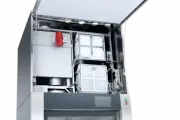
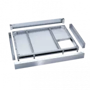
de - Installationshinweise 5 Schrauben Sie die Schrauben (Torx T 20 und T 30) aus der Holzver-kleidung heraus. Entfernen Sie die Holzverkleidung. Heben Sie den Trockner mit dem Hubwagen an. Montieren Sie die mitgelieferten Standfüße (4 Stück) Trockner aufstellen Stellen Sie den Trockner au...
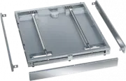
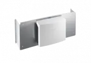
de - Installationshinweise 7 Tipp: Nehmen Sie für die korrekte Ausrichtung eine Wasserwaage zur Hilfe. Gasbeheizte Trockner oder Trockner, die auf einem Sockel oderOffshore installiert werden, müssen nach der Aufstellung unbedingtmit Spannlaschen am Boden befestigt werden. Gefahr von Gasaustritt...
Quick Guide Miele PDR 516 SL ROP [EL IGS]


Summary
Contents 2 Warning and Safety instructions ............................................................................................. 4 Extended documentation ............................................................................................................. 4 Appropriate use .............
Contents 3 Installation of electrically heated and gas-heated variants ..................................................... 33 Air intake/exhaust air................................................................................................................ 33 Gas connection (only for gas-heate...
Warning and Safety instructions 4 It is essential to read these instructions. Extended documentation This document contains essential information. You can access the full operating instruc-tions and other up-to-date documentation for your appliance on the Miele website:https://www.miele.co.uk/prof...
Miele Manuals
-
 Miele APWM 063
Installation Manual
Miele APWM 063
Installation Manual
-
 Miele APWM 066
Installation Manual
Miele APWM 066
Installation Manual
-
 Miele UO 811-30
Installation Manual
Miele UO 811-30
Installation Manual
-
 Miele UO 413-30
Installation Manual
Miele UO 413-30
Installation Manual
-
 Miele UO 814-25
Installation Manual
Miele UO 814-25
Installation Manual
-
 Miele UO 818/418-25
Installation Manual
Miele UO 818/418-25
Installation Manual
-
 Miele APCL 043
User Manual
Miele APCL 043
User Manual
-
 Miele APWM 062
Installation Manual
Miele APWM 062
Installation Manual
-
 Miele APWM 065
Installation Manual
Miele APWM 065
Installation Manual
-
 Miele APWM 070
Installation Manual
Miele APWM 070
Installation Manual
-
 Miele APWM 069
Installation Manual
Miele APWM 069
Installation Manual
-
 Miele APWM 020
Installation Manual
Miele APWM 020
Installation Manual
-
Miele APWM 020
User Manual
-
 Miele SC
Installation Manual
Miele SC
Installation Manual
-
 Miele PR
Installation Manual
Miele PR
Installation Manual
-
 Miele FP 900
Installation Manual
Miele FP 900
Installation Manual
-
 Miele RP 900
Installation Manual
Miele RP 900
Installation Manual
-
 Miele APCL 046
User Manual
Miele APCL 046
User Manual
-
 Miele APCL 047
User Manual
Miele APCL 047
User Manual
-
 Miele APWM 019
Installation Manual
Miele APWM 019
Installation Manual