Makita GRU02M1 - Manuals
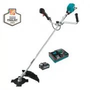
User Manual Makita GRU02M1


Summary
2 ENGLISH ENGLISH (Original instructions) SPECIFICATIONS Model: GRU02 GRU03 Handle type Bike handle Loop handle No load speed (at each rotation speed level) 3: 0 - 7,000 /min 2: 0 - 5,500 /min 1: 0 - 4,600 /min Overall length (without cutting tool and battery) 1,815 mm (71-1/2″) Nylon cord diameter ...
6 ENGLISH 3. Never apply the segment between 12 and 2 o’clock. 4. Never apply the segment between 11 and 12 o’clock and between 2 and 5 o’clock, unless the operator is well trained and experienced and does it at his/her own risk. 12 1 2 3 4 5 8 9 10 11 5. Never use cutting blades close to hard objec...
7 ENGLISH Important safety instructions for battery cartridge 1. Before using battery cartridge, read all instruc- tions and cautionary markings on (1) battery charger, (2) battery, and (3) product using battery. 2. Do not disassemble or tamper the battery cartridge. It may result in a fire, excessi...
Makita Brush Cutters Manuals
-
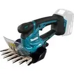 Makita DUM604ZX
User Manual
Makita DUM604ZX
User Manual
-
 Makita GAU02Z
User Manual
Makita GAU02Z
User Manual
-
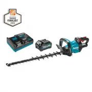 Makita GHU01M1
User Manual
Makita GHU01M1
User Manual
-
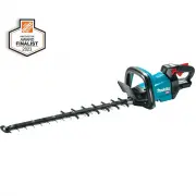 Makita GHU01Z
User Manual
Makita GHU01Z
User Manual
-
 Makita GHU02M1
User Manual
Makita GHU02M1
User Manual
-
 Makita GHU02M1-BL4040
User Manual
Makita GHU02M1-BL4040
User Manual
-
 Makita GHU02Z
User Manual
Makita GHU02Z
User Manual
-
 Makita GHU03M1
User Manual
Makita GHU03M1
User Manual
-
 Makita GHU03Z
User Manual
Makita GHU03Z
User Manual
-
 Makita GHU04M1
User Manual
Makita GHU04M1
User Manual
-
 Makita GHU04Z
User Manual
Makita GHU04Z
User Manual
-
 Makita GHU05M1
User Manual
Makita GHU05M1
User Manual
-
 Makita GHU05Z
User Manual
Makita GHU05Z
User Manual
-
 Makita GRU02Z
User Manual
Makita GRU02Z
User Manual
-
 Makita GRU05PM
User Manual
Makita GRU05PM
User Manual
-
 Makita MU04Z
User Manual
Makita MU04Z
User Manual
-
 Makita UH004G
User Manual
Makita UH004G
User Manual
-
 Makita UH005G
User Manual
Makita UH005G
User Manual
-
 Makita UH4261
User Manual
Makita UH4261
User Manual
-
Makita UH4861
User Manual