Honeywell OELD - Manuals
Honeywell OELD – User Manual, Manual in PDF format online.
Manuals:
User Manual Honeywell OELD


Summary
OELD User Manual (3018M5000_1-3) Revision 1, Issue 3 Content 1 Safety....................................................................................................................................................... 2 1.1 Safety Warnings and Information ............................................
OELD User Manual (3018M5000_1-3) Revision 1, Issue 3 1 Safety 1.1 Safety Warnings and Information Special Conditions for Safe Use – Terminals In order to comply with the ATEX Certification, the following special conditions of use must be ad-hered to: - 1. Not more than one single or multiple strand ...
OELD User Manual (3018M5000_1-3) Revision 1, Issue 3 1.3 Waste Electrical and Electronic Equipment (WEEE) Directive This symbol indicates that this product and/or parts of the product may not be treated as household or municipal waste. W aste electrical products (end of life) should be recov-ered/re...
Manual Honeywell OELD


Summary
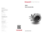
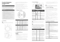
OELD Smart Junction Box Quick Start Guide WARNING Read and understand the OELD Operating Instructions before installing, operating or servicing this product. These are available for download from the Honeywell Analytics website. Visit www.honeywellanalytics.com 1 Safety Warnings and Information WARN...
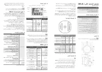
OELD ـل يكذلا ليصوتلا قودنص عيرسلا ءدبلا ليلد ريذحت وأ ،جتنملا اذه بيكرت لبق اهمهفو OELD ليغشت تاداشرإ ةءارق ىلع صرحا ـل ينورتكللإا عقوملا نم تاداشرلإا هذه ليزنت نكمي .هتنايص وأ ،هليغشت ةرايزب ل ّضفت . Honeywell Analytics www.honeywellanalytics.com ةملاسلا تامولعمو تاريذحت 1 ريذحت يف ةمئلاملا ةطلسلا...
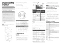
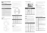
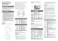
OELD – Intelligentes Anschluss-Terminal Kurzanleitung WARNUNG Lesen Sie die OELD-Betriebsanleitung aufmerksam durch, bevor Sie das Produkt installieren, ver wenden oder war ten. Diese steht auf der Webseite von Honey well Analy tics zum Download bereit: Besuchen Sie w w w.honey wellanaly tics.com 1 ...
Honeywell Manuals
-
 Honeywell DT8050A
Installation Manual
Honeywell DT8050A
Installation Manual
-
Honeywell DT8050A
Manual
-
Honeywell DT8050A
User Manual
-
 Honeywell DT8050
Manual
Honeywell DT8050
Manual
-
Honeywell DT8050
User Manual
-
 Honeywell TPFIT25WK
User Manual
Honeywell TPFIT25WK
User Manual
-
Honeywell TPFIT25AWK
User Manual
-
Honeywell TPFIT32WK
User Manual
-
 Honeywell TPFIT32AWK
User Manual
Honeywell TPFIT32AWK
User Manual
-
 Honeywell 24DX47
User Manual
Honeywell 24DX47
User Manual
-
Honeywell 24DX47
Manual
-
 Honeywell TPFIT50PWK
User Manual
Honeywell TPFIT50PWK
User Manual
-
 Honeywell TPFIT50WK
User Manual
Honeywell TPFIT50WK
User Manual
-
Honeywell TPFIT50AWK
User Manual
-
Honeywell TPFIT50APWK
User Manual
-
 Honeywell 00010
User Manual
Honeywell 00010
User Manual
-
 Honeywell ADVBLEWIFI
Manual
Honeywell ADVBLEWIFI
Manual
-
Honeywell ADVBLEWIFI
User Manual
-
Honeywell ADVBLE
Manual
-
Honeywell ADVBLE
User Manual