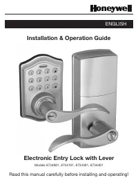
Page 2 - Index; INSTALLATION INSTRUCTIONS
Page 2 Index INSTALLATION INSTRUCTIONS Package Contents / Tools Required ........................................................... Page 1 Prepare Door and Jamb ............................................................................... Page 2 Adjusting Latch / Installing Latch ...................
Page 3 - Package Contents; • Phillips Screwdriver
Page 1 INSTALLATION INSTRUCTIONS Package Contents Tools Required Tools Required for Installation on Pre-drilled Doors: • Phillips Screwdriver Tools Required for Installation on Doors That Require Drilling: • Drill• Tape Measure• Pencil• 2-1/8” (54mm) Drill Hole Saw• 1” (25mm) Drill• 1/16” (2mm) Dril...
Page 4 - PREPARE DOOR AND JAMB
Page 2 NOTE: For installation on doors with pre-drilled holes skip to 4e. 1. TEMPLATE a. Cut out template printed on page 17 of this Manual (Figure 1a). b. Fold template and place on door 36” (915mm) from the ground as marked (Figure 1b). 2. MARK THE DOOR FOR DRILLING b. Mark center hole on door edg...
Page 5 - ADJUSTING LATCH; PULL; NOTE: Curved part of Latch always faces; INSTALLING LATCH
Page 3 5. INSTALLING THE LATCH (need phillips head screwdriver) a. Make sure the face plate sits flush with the door. Do not force the Latch into the mortise flush. Chisel out excess material if necessary for a flush fit (Figure 5a). b. Using two 3/4” (19mm). screws provided, screw the Latch into th...
Page 6 - INSTALLING EXTERIOR ASSEMBLY; SECURING THE EXTERIOR ASSEMBLY TO THE DOOR; g. Tighten securely with a hand held Phillips Screwdriver.; DO NOT OVER TIGHTEN; using the Mounting Plate upper hole as a guide (Figure 8a).; during handling and installation.; VERTICAL POSITION; . Route the Control Wire through
Page 4 NOTE: Tailpiece must be positioned vertically INSTALLING EXTERIOR ASSEMBLY Rubber Gasket Control Wire Tailpiece (Vertical) Latch Hole Figure 6a-b Figure 6c 7. SECURING THE EXTERIOR ASSEMBLY TO THE DOOR a. From the side marked “This side against door”, route the Control Wire through the rectan...
Page 7 - INSTALLING INTERIOR ASSEMBLY; ATTACH THE CONTROL WIRE TO THE INTERIOR ASSEMBLY; the Interior Assembly to the Mounting Plate.; DO NOT OVER TIGHTEN SCREWS; NOTE: Lock and unlock using Interior Lever to see if the
Page 5 INSTALLING INTERIOR ASSEMBLY 9. ATTACH THE CONTROL WIRE TO THE INTERIOR ASSEMBLY a. Use care to attach the Control Wire male plug to the Interior Assembly female socket connector (Figure 9a). b. Do not force the Control Wire male plug into the Interior Assembly female socket connector (Figure...
Page 8 - REVERSIBLE LEVER HANDLES
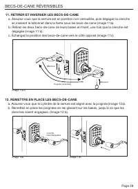
Page 6 11. REMOVING AND REVERSING LEVER HANDLES a. Make sure the Door Lock is in the unlocked position and then release catch by inserting Lock Stick into the slot on the underside of levers (Figure 11a). b. Remove both lever handles from the bases by pulling away from door when the catch is release...
Page 9 - Installing Batteries; NOTE: Do not touch the Keypad until the blue light turns off.; INSTALLATION OVERVIEW
Page 7 13. Installing Batteries a. Insert 4 AA high quality Alkaline batteries into the Battery Compartment in the direction noted +/- on the Compartment. The Lock will beep 2 times, the keypad will illuminate blue, and the Honeywell button will flash green twice to signify that it has received powe...
Page 10 - OPERATION INSTRUCTIONS; Exterior Assembly Overview; Indicator light; Factory Settings
Page 8 OPERATION INSTRUCTIONS Exterior Assembly Overview Indicator light Green • Indicates Successful Programming Step • Indicates Unlocking is Successful Red • Indicates Failed Programming Step • Indicates Locking is Successful Electronic lock requires (4) High Quality AA Alkaline batteries. When a...
Page 11 - new Re-enter
Page 9 TO UNLOCK THE LOCK Using Keypad: Enter a valid User Code (default code is 1234) and press and hear1 beep and lights green. TO LOCK THE LOCK Using Keypad: Press and then hear 2 beeps and lights red. CHANGE CURRENT OR PRESET PROGRAMING CODE Factory default Programming Code = 123456, this is the...
Page 12 - To cancel Auto Lock set the time to 00, enter the following:
Page 10 DELETE ONE EXISTING OR PRESET USER CODE The unit comes with a factory User ID = 01 for User Code = 1234. IMPORTANT: To delete 1 User Code , the lock must have more than 1 User Code in its database. SET OR CANCEL AUTO LOCK You can set the lock to automatically close after each time the lock i...
Page 13 - , the system will remain in Vacation Mode.; Hear 1 beep and Light Indicator illuminates green then lock door
Page 11 NOTE: If you only press the for more than 3 seconds but do not input PC , the system will remain in Vacation Mode. Warning sounds and LED flashes red after 4 incorrect code attempts: Keypad shuts down for 30 seconds. To reset the lock to the original factory settings including the Programmin...
Page 14 - Issue
Page 12 NOTE: When battery is under low voltage, the lock will give the (Low Battery Warning: Beeps and LED flashes red for 5 seconds). During this time your lock can still work. However once the voltage is lower than 4.3V (called Super-Low Voltage), the operation of the locking and unlocking will n...
Page 15 - CONSUMER ASSISTANCE; * Insert correct Country Code
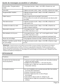
Page 13 Unlock / Valid programming: 1 long beep and LED illuminates green Lock: 2 short beeps and LED illuminates red Invalid Programming: 2 short beeps and LED flashes red twice Low Voltage: Beeps for 5 seconds (7/9 times depends on operation is unlock/lock) Super Low Voltage: 4 short beeps and LED...
Page 16 - Programming Record
Page 14 My Codes: Date Created Programming Code (6 digits) / / User Code 01 (4-8 digits) / / User Code 02 (4-8 digits) / / User Code 03 (4-8 digits) / / User Code 04 (4-8 digits) / / User Code 05 (4-8 digits) / / User Code 06 (4-8 digits) / / User Code 07 (4-8 digits) / / User Code 08 (4-8 digits) /...
Page 17 - Programming Record Continued
Page 15 My Codes: Date Created User Code 26 (4-8 digits) / / User Code 27 (4-8 digits) / / User Code 28 (4-8 digits) / / User Code 29 (4-8 digits) / / User Code 30 (4-8 digits) / / User Code 31 (4-8 digits) / / User Code 32 (4-8 digits) / / User Code 33 (4-8 digits) / / User Code 34 (4-8 digits) / /...
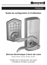
Page 23 - Veuillez lire ce manuel avec soin avant; Guide de configuration et d’utilisation; FRANÇAIS
The Honeywell Trademark is used under license from Honeywell International Inc. Honeywell International Inc. makes no representations or warranties with respect to this product. www.honeywellsafes.com Modèle 8734001, 8734101, 8734301, 8734401 Veuillez lire ce manuel avec soin avant d’installer et d’...
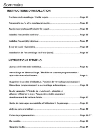
Page 24 - Sommaire; INSTRUCTIONS D’INSTALLATION
Page 22 Sommaire INSTRUCTIONS D’INSTALLATION Contenu de l’emballage / Outils requis ...................................................... Page 23 Préparez la porte et le montant de porte ................................................... Page 24 Ajustement du loquet/Installer le loquet ..............
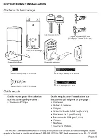
Page 25 - Contenu de l’emballage; • Tournevis Phillips
Page 23 INSTRUCTIONS D’INSTALLATION Contenu de l’emballage Outils requis Outils requis pour l’installation sur les portes pré-percées : • Tournevis Phillips Outils requis pour l’installation sur les portes qui exigent un perçage : • Perceuse• Ruban à mesurer• Crayon• Scie-cloche de 2-1/8 po (54 mm)•...
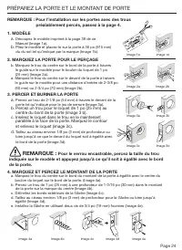
Page 26 - c. Insérez le loquet dans le trou en le maintenant; PRÉPAREZ LA PORTE ET LE MONTANT DE PORTE; REMARQUE :
Page 24 REMARQUE : Pour l’installation sur les portes avec des trous préalablement percés, passez à la page 4. 1. MODÈLE a. Découpez le modèle imprimé à la page 39 de ce Manuel (Image 1a) . b. Pliez le modèle et placez-le sur la porte à 36 po (915 mm) du du sol tel qu’indiqué par la marque (Image 1b...
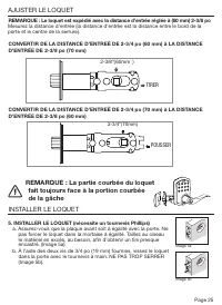
Page 27 - AJUSTER LE LOQUET; REMARQUE : La partie courbée du loquet; INSTALLER LE LOQUET; TIRER
Page 25 5. INSTALLER LE LOQUET (nécessite un tournevis Phillips) a. Assurez-vous que la plaque avant soit à égalité avec la porte. Ne pas forcer le loquet dans la mortaise à égalité. Taillez au ciseau le matériel en excès, au besoin, afin d’obtenir un fini presque encastré. (Image 5a). b. À l’aide d...
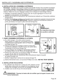
Page 28 - FIXER L’ENSEMBLE EXTÉRIEUR À LA PORTE; INSTALLATION DE L’ENSEMBLE EXTÉRIEUR; INSTALLEZ L’ASSEMBLAGE EXTÉRIEUR
Page 26 REMARQUE : Le manchon doit être en position verticale Joint en caoutchouc Câble de commande Manchon (Vertical) Trou du loquet Image 6a-b Image 6c 7. FIXER L’ENSEMBLE EXTÉRIEUR À LA PORTE a. Du côté marqué « Ce côté contre la porte », faites passer le Câble de commande à travers l’emplacement...
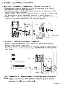
Page 29 - INSTALLEZ L’ENSEMBLE INTÉRIEUR; ATTACHEZ LE CÂBLE DE COMMANDE À L’ENSEMBLE INTÉRIEUR; dans le connecteur femelle de l’Ensemble intérieur (Image 9d).; ATTACHEZ L’ENSEMBLE INTÉRIEUR À LA PORTE; l’Ensemble intérieur à la Plaque de montage.; NE PAS TROP SERRER LES VIS
Page 27 INSTALLEZ L’ENSEMBLE INTÉRIEUR 9. ATTACHEZ LE CÂBLE DE COMMANDE À L’ENSEMBLE INTÉRIEUR a. Prenez soin d’attacher la fiche mâle du câble de commande au connecteur femelle de l’Ensemble intérieur (Image 9a). b. Ne pas forcer la fiche mâle du câble de commande dans le connecteur femelle de l’En...
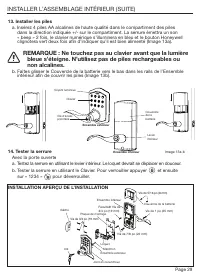
Page 31 - et ensuite; INSTALLATION APERÇU DE L’INSTALLATION; REMARQUE : Ne touchez pas au clavier avant que la lumière
Page 29 13. Installer les piles a. Insérez 4 piles AA alcalines de haute qualité dans le compartiment des piles dans la direction indiquée +/- sur le compartiment. La serrure émettra un son « beep » 2 fois, le clavier numérique s’illuminera en bleu et le bouton Honeywell clignotera vert deux fois af...
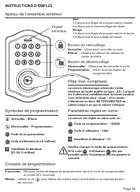
Page 32 - INSTRUCTIONS D'EMPLOI; Aperçu de l'ensemble extérieur; Bouton de verrouillage; Paramètres réglés en usine
Page 30 INSTRUCTIONS D'EMPLOI Aperçu de l'ensemble extérieur Voyant lumineux Vert • Indique une étape de programmation réussie• Indique que le déverrouillage est réussi Rouge • Indique une étape de programmation échouée• Indique que le verrouillage est réussi La serrure électronique nécessite 4 pile...
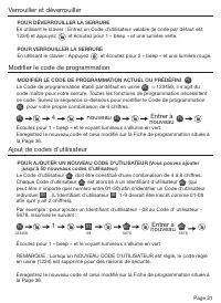
Page 34 - SUPPRIMER UN CODE D'UTILISATEUR EXISTANT OU PRÉDÉFINI; RÉGLER OU ANNULER LE VERROUILLAGE AUTOMATIQUE
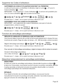
Page 32 SUPPRIMER UN CODE D'UTILISATEUR EXISTANT OU PRÉDÉFINI L'unité est fournie avec un Identifiant d'utilisateur réglé en usine ID = 01 pour le Code d’utilisateur UC = 1234. IMPORTANT : Pour supprimer 1 Code d’utilisateur UC , la serrure doit posséder plus d'un (1) Code d’utilisateur UC dans sa b...
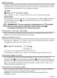
Page 35 - REMARQUE : Si vous appuyez uniquement sur; le système demeurera en mode vacances.
Page 33 Mode Vacanes 10 1 PC Après 4 tentatives incorrectes de saisie du code, un avertissement sonore se fait entendre : Le clavier s’éteint pendant 30 secondes. Période de « Lock out » sécurisée Vous pouvez « supprimer » ou « allumer » le son sur votre serrure en entrant le suivant. (Le réglage en...
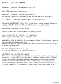
Page 37 - AIDE AU CONSOMMATEUR; ADRESSE : Département d’aide au consommateur
Page 35 Déverrouiller / Programmation valide : 1 long signal sonore « beep » et le DEL s'illumine en vert Verrouiller : 2 signaux sonores courts « beep » et le DEL s'illumine en rouge Programmation invalide : 2 signaux sonores courts « beep » et le DEL s'illumine en rouge deux fois Faible tension : ...
Page 38 - Fiche de programmation
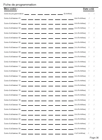
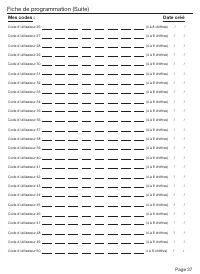
Page 36 Mes codes : Date créé Code de programmation (6 chiffres) / / Code d’utilisateur 01 (4 à 8 chiffres) / / Code d’utilisateur 02 (4 à 8 chiffres) / / Code d’utilisateur 03 (4 à 8 chiffres) / / Code d’utilisateur 04 (4 à 8 chiffres) / / Code d’utilisateur 05 (4 à 8 chiffres) / / Code d...
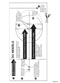
Page 41 - DU MODÈLE; PLIEZ ICI SUR LE
Page 39 THEN DRILL 1” (25mm) HOLE IN CENTER DOOR OF EDGE 2” (50mm) IN DEPTH MARK FOR 1-3/4” (45mm) DOOR DRILL 2-1/8” (54mm) HOLE MARK FOR 1-3/8” (35mm) DOOR IMPO RT ANT! PLACE TEMPL AT E ON HIGH EDGE OF DOOR BEVEL DU MODÈLE Distance d'entr ée de 2-3/8 po (60MM) Distance d'entr ée de 2-3/4 po (70MM) ...
Page 45 - ¡Lea este manual cuidadosamente; Guía de instalación y funcionamiento; ESPAÑOL
La marque de commerce de Honeywell est utilisée sous licence de Honeywell International Inc. Honeywell International Inc. ne fait aucune représentation ou garantie concernant ce produit. www.honeywellsafes.com Modelos 8734001, 8734101, 8734301, 8734401 ¡Lea este manual cuidadosamente antes de instal...
Page 46 - Índice; INSTRUCCIONES DE INSTALACIÓN
Page 44 Índice INSTRUCCIONES DE INSTALACIÓN Contenido del paquete / Herramientas necesarias ................................... Página 45 Preparar la puerta y el quicio ....................................................................... Página 46 Ajustar el pestillo / Instalar el pestillo .........
Page 47 - INSTRUCCIONES DE FUNCIONAMIENTO; Contenido del paquete; • Destornillador de cruz
Page 45 INSTRUCCIONES DE FUNCIONAMIENTO Descripción general del conjunto exterior ................................................ Página 52 Cerrar y abrir / Cambiar el código de programación / Agregar códigos de usuario................................... ..................................... Página...
Page 48 - PREPARAR LA PUERTA Y EL QUICIO; Para un pestillo empotrable, taladre un agujero del tamaño
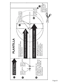
Page 46 NOTA: Para instalar en puertas con agujeros perforados previamente vaya a la página 4e. 1. PLANTILLA a. Corte la plantilla impresa en la página 61 de este manual (Figura 1a). b. Doble la plantilla y ubíquela en la puerta a 36” (915mm) del piso según lo marcado (Figura 1b). 2. MARQUE LA PUERT...
Page 49 - INSTALE EL PESTILLO (se necesita el destornillador de cruz); AJUSTAR EL PESTILLO; EMPUJE; NOTA: La parte curva del pestillo debe; INSTALAR EL PESTILLO
Page 47 5. INSTALE EL PESTILLO (se necesita el destornillador de cruz) a. Asegúrese de que el frente de la placa esté nivelado con la puerta. No fuerce el pestillo en la muesca de nivelación. Cincele el material sobrante si es necesario para que quede nivelado (Figura 5a). b. Con dos de los tornillo...
Page 50 - ASEGURE EL CONJUNTO EXTERIOR A LA PUERTA; NO APRIETE EN EXCESO; INSTALACIÓN OPCIONAL; INSTALAR EL CONJUNTO EXTERIOR; POSICIÓN VERTICAL
Page 48 7. ASEGURE EL CONJUNTO EXTERIOR A LA PUERTA a. Desde el lado marcado “Este lado contra la puerta”, dirija el cable de control a través de la ranura rectangular en la placa de montaje (Figura 7a). b. Coloque la placa de montaje contra la puerta y haga que el extremo final pase a través del ag...
Page 51 - INSTALAR EL CONJUNTO INTERIOR; FIJE EL CABLE DE CONTROL AL CONJUNTO INTERIOR; NO APRIETE EN EXCESO LOS TORNILLOS
Page 49 INSTALAR EL CONJUNTO INTERIOR Tornillos de 5/16” (8mm) Tornillo de 1” (25mm) NOTA: Cierre y abra con el pomo interior para ver si el pestillo del cerrojo abre y cierra fácilmente. Figura 10a-b Figura 9a-d 9. FIJE EL CABLE DE CONTROL AL CONJUNTO INTERIOR a. Tenga cuidado de sujetar el enchufe...
Page 52 - MANIJAS REVERSIBLES DE LA PALANCA
Page 50 Figura 11a-c Figura 12a Figura 12b 11. QUITAR E INTERCAMBIAR LAS MANIJAS DE LA PALANCA a. Asegúrese de que la cerradura de la puerta esté abierta y luego libere la trabilla introduciendo la clavija de cierre dentro de la ranura en la parte inferior de las palancas (Figura 11a). b. Saque amba...
Page 53 - DESCRIPCIÓN GENERAL DE LA INSTALACIÓN; NOTA: No toque el teclado hasta que la luz azul esté apagada.
Page 51 13. Instalación de las baterías a. Inserte 4 baterías AA alcalinas de alta calidad en el compartimiento de baterías en la dirección marcada +/- en el compartimiento. El cerrojo pitará 2 veces, el teclado numérico se iluminará de azul y el botón Honeywell destellará dos veces en verde para in...
Page 54 - Descripción general del conjunto exterior; Botón de cierre; Configuraciones de fábrica
Page 52 INSTRUCCIONES DE FUNCIONAMIENTO Descripción general del conjunto exterior Luz indicadora Verde • Indica un paso exitoso de programación• Indica una apertura exitosa Rojo • Indica un paso fallido de programación• Indica un cierre exitoso Las cerraduras electrónicas necesitan (4) baterías AA a...
Page 56 - ELIMINAR UN CÓDIGO DE USUARIO EXISTENTE O PRECONFIGURADO; ESTABLEZCA O CANCELE EL CIERRE AUTOMÁTICO
Page 54 DESACTIVAR: Mientras aún esté en modo de cierre automático, abra la puerta usando PC , en los próximos 10 segundos debe mover la perilla manualmente hasta que esté en posición de cerrado; espere más de 2 segundos para mover la perilla de regreso hacia la posición de abierto. El modo de cierr...
Page 57 - NOTA: Si solo presiona el botón; , el sistema permanecerá
Page 55 10 1 PC Si se ingresa 4 veces un código incorrecto, sonará una advertencia y la luz LED roja brillará: el teclado numérico se apagará por 30 segundos. Período de bloqueo seguro Usted puede “silenciar” o “encender el sonido” de su cerradura al introducir lo siguiente. (La configuración de fáb...
Page 58 - RESOLUCIÓN DE PROBLEMAS DE INSTALACIÓN; Problema; GUÍA DE MENSAJES DE USO FÁCIL PARA EL CONSUMIDOR
Page 56 RESOLUCIÓN DE PROBLEMAS DE INSTALACIÓN Problema Solución La cerradura no funcionará electrónicamente. • Revise que todas las baterías estén en buenas condiciones sean alcalinas y de alta calidad. • Revise que la polaridad (+ -) de todas las baterías sea correcta.• Revise que el cable de cont...
Page 59 - ASISTENCIA AL CONSUMIDOR; * Introduzca el código correcto del país.
Page 57 Abrir / Programación válida: 1 pitido largo y la luz LED se iluminará de verde Cerrar: 2 pitidos cortos y la luz LED se iluminará de rojo Programación inválida: 2 pitidos cortos y la luz LED brillará en rojo dos veces Bajo voltaje: Suenan pitidos por 5 segundos (7/9 veces dependiendo de si l...
Page 60 - Registro de programación
Page 58 Mis códigos: Fecha de creación Código de programación (6 dígitos) / / Código de usuario 01 (4-8 dígitos) / / Código de usuario 02 (4-8 dígitos) / / Código de usuario 03 (4-8 dígitos) / / Código de usuario 04 (4-8 dígitos) / / Código de usuario 05 (4-8 dígitos) / / Código de usuario 06 (4-8 d...
Page 63 - PLANTILLA
Page 61 THEN DRILL 1” (25mm) HOLE IN CENTER DOOR OF EDGE 2” (50mm) IN DEPTH MARK FOR 1-3/4” (45mm) DOOR DRILL 2-1/8” (54mm) HOLE MARK FOR 1-3/8” (35mm) DOOR IMPO RT ANT! PLACE TEMPL AT E ON HIGH EDGE OF DOOR BEVEL PLANTILLA ENTRADA DE CERRADURA DE 2-3/8” (60MM) ENTRADA DE CERRADURA DE 2-3/4” (70MM) ...


 Honeywell DT8050A
Installation Manual
Honeywell DT8050A
Installation Manual
 Honeywell DT8050
Manual
Honeywell DT8050
Manual
 Honeywell TPFIT25WK
User Manual
Honeywell TPFIT25WK
User Manual
 Honeywell TPFIT32AWK
User Manual
Honeywell TPFIT32AWK
User Manual
 Honeywell 24DX47
User Manual
Honeywell 24DX47
User Manual
 Honeywell TPFIT50PWK
User Manual
Honeywell TPFIT50PWK
User Manual
 Honeywell TPFIT50WK
User Manual
Honeywell TPFIT50WK
User Manual
 Honeywell 00010
User Manual
Honeywell 00010
User Manual
 Honeywell ADVBLEWIFI
Manual
Honeywell ADVBLEWIFI
Manual