Grizzly Industrial G0926 - Manuals

User Manual Grizzly Industrial G0926


Summary
Table of Contents INTRODUCTION ............................................... 2 Contact Info.................................................... 2Manual Accuracy ........................................... 2Identification ................................................... 3Controls & Component...
-2- Model G0926 (Mfd. Since 11/20) We stand behind our machines! If you have ques-tions or need help, contact us with the information below. Before contacting, make sure you get the serial number and manufacture date from the machine ID label. This will help us help you faster. Grizzly Technical Sup...
Model G0926 (Mfd. Since 11/20) -3- Identification To reduce your risk of serious injury, read this entire manual BEFORE using machine. Become familiar with the names and locations of the controls and features shown below to better understand the instructions in this manual. Blade Tension Knob Motor ...
Grizzly Industrial Band Saws Manuals
-
 Grizzly Industrial G0513A40
User Manual
Grizzly Industrial G0513A40
User Manual
-
 Grizzly Industrial G0513X2
User Manual
Grizzly Industrial G0513X2
User Manual
-
 Grizzly Industrial G0513X2BF
User Manual
Grizzly Industrial G0513X2BF
User Manual
-
Grizzly Industrial G0513X2BF
Manual
-
 Grizzly Industrial G0514X
User Manual
Grizzly Industrial G0514X
User Manual
-
Grizzly Industrial G0514X
Manual
-
 Grizzly Industrial G0514X2B
User Manual
Grizzly Industrial G0514X2B
User Manual
-
 Grizzly Industrial G0531B
User Manual
Grizzly Industrial G0531B
User Manual
-
Grizzly Industrial G0531B
Manual
-
 Grizzly Industrial G0555
User Manual
Grizzly Industrial G0555
User Manual
-
Grizzly Industrial G0555
Manual
-
 Grizzly Industrial G0555LX
User Manual
Grizzly Industrial G0555LX
User Manual
-
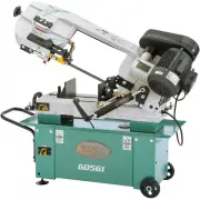 Grizzly Industrial G0561
User Manual
Grizzly Industrial G0561
User Manual
-
 Grizzly Industrial G0568
User Manual
Grizzly Industrial G0568
User Manual
-
Grizzly Industrial G0568
Manual
-
 Grizzly Industrial G0613
User Manual
Grizzly Industrial G0613
User Manual
-
 Grizzly Industrial G0636X
User Manual
Grizzly Industrial G0636X
User Manual
-
 Grizzly Industrial G0640X
User Manual
Grizzly Industrial G0640X
User Manual
-
 Grizzly Industrial G0701
User Manual
Grizzly Industrial G0701
User Manual
-
 Grizzly Industrial G0803Z
User Manual
Grizzly Industrial G0803Z
User Manual