Epson 2170 - Manuals
Epson 2170 – Manual in PDF format online.
Manuals:
Manual Epson 2170
1

2

3

4

5

6

7

8

9

10

11

12

13

14

15

16

17

18

19

20

21

22

23

24

25

26

27

28

29

30

31

32

33

34

35

36

37

38

39

40

41

42

43

44

45

46

47

48

49

50

51

52

53

54

55

56

57

58

59

60

61

62

63

64

65

66

67

68

69

70

71

72

73

74

75

76

77

78

79

80

81

82

83

84

85

86

87

88

89

90

91

92

93

94

95

96

97

98

99

100

101

102

103

104

105

106

107

108

109

110

111

112

113

114

115

116

117

118

119

120

121

122

123

124

125

126

127

128

129

130

131

132

133

134

135

136

137

138

139

140

141

142

143

144

145

146

147

148

149

150

151

152

153

154

155

156

157

158

159

160

161

162

163

164

165

166

167

168

169

170

171

172

173

174

Summary
Page 2 - NOTICE
NOTICE • All right reserved. Reproduction of any part of this manual in any form wharsoever without SEIKO EPSON’s express written permission is forbidden. • The contents of this manual are subject to change without notice. • All efforts have been made to ensure the accuracy of the contents of this m...
Page 4 - PREFACE; The contents of this manual are subject to change without notice.
PREFACE This manual describes functions, theory of electrical and mechanical operations, maintenance, and repair ofthe FX-2170. The instructions and procedures included herein are intended for the experienced repairtechnician, and attention should be given to the precautions on the preceding page. T...
Page 5 - REVISION SHEET; Revision; st issued
REVISION SHEET Revision Issued Date Revision Page Rev. A October 13, 1995 1st issued
Epson Manuals
-
 Epson V11HA52820
User Manual
Epson V11HA52820
User Manual
-
Epson V11HA67820
User Manual
-
 Epson V12H004UA3
User Manual
Epson V12H004UA3
User Manual
-
Epson V12H004UA3
Troubleshooting Guide
-
 Epson V11HA85020
Installation Manual
Epson V11HA85020
Installation Manual
-
 Epson C11CK65201
User Manual
Epson C11CK65201
User Manual
-
 Epson V11H980020
Manual
Epson V11H980020
Manual
-
 Epson HOME CINEMA 3200
Manual
Epson HOME CINEMA 3200
Manual
-
 Epson HOME CINEMA 3800
User Manual
Epson HOME CINEMA 3800
User Manual
-
Epson HOME CINEMA 3800
Manual
-
 Epson B11B252201
User Manual
Epson B11B252201
User Manual
-
Epson C11CJ91201
User Manual
-
 Epson WF 7210
Installation Manual
Epson WF 7210
Installation Manual
-
Epson WF 7210
Manual
-
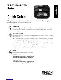 Epson WF 7720
User Manual
Epson WF 7720
User Manual
-
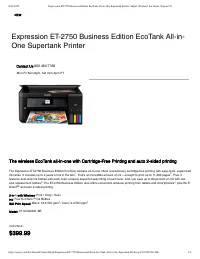 Epson ET 2750
User Manual
Epson ET 2750
User Manual
-
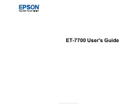 Epson ET 7700
User Manual
Epson ET 7700
User Manual
-
Epson ET 7700
Manual
-
Epson ET 7700
Troubleshooting Guide
-
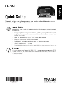 Epson ET 7750
Troubleshooting Guide
Epson ET 7750
Troubleshooting Guide