DeLonghi DFS 090 SO- Manuals
DeLonghi DFS 090 SO– User Manual in PDF format online.
Manuals:
User Manual DeLonghi DFS 090 SO


Summary
2 Introduction Congratulations on your purchase of this Delonghi Cooker which has been carefully designed and produced to give you many years of satisfactory use. Before using this appliance it is essential that the following instructions are carefully read andfully understood. We would emphasise th...
3 Important precautions and recommendations After having unpacked the appliance, check to ensure that it is not damaged.In case of doubt, do not use it and consult your supplier or a professionally qualified techni-cian.Packing elements (i.e. plastic bags, polystyrene foam, nails, packing straps, et...
4 1 Features and technical data Gas burners 1. Auxiliary burner (A) 1,00 kW 2. Semi-rapid burner (SR) 1,90 kW3. Rapid burner (R) 3,15 kW 4. Double-ring burner (PB) 3,45 kW Fig. 1.1 2 4 2 1 3
DeLonghi Manuals
-
 DeLonghi EN640 B
User Manual
DeLonghi EN640 B
User Manual
-
 DeLonghi EN640 W
User Manual
DeLonghi EN640 W
User Manual
-
 DeLonghi ENV95
User Manual
DeLonghi ENV95
User Manual
-
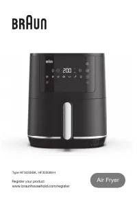 DeLonghi HF3030IBK
User Manual
DeLonghi HF3030IBK
User Manual
-
 DeLonghi CH301
User Manual
DeLonghi CH301
User Manual
-
DeLonghi CH301
Manual
-
 DeLonghi FDM73
Manual
DeLonghi FDM73
Manual
-
 DeLonghi EXAM440 55 B
Manual
DeLonghi EXAM440 55 B
Manual
-
 DeLonghi EXAM440 55 G
User Manual
DeLonghi EXAM440 55 G
User Manual
-
 DeLonghi KF101AI
User Manual
DeLonghi KF101AI
User Manual
-
 DeLonghi KM336
Manual
DeLonghi KM336
Manual
-
 DeLonghi 0105051106
User Manual
DeLonghi 0105051106
User Manual
-
 DeLonghi 0114581002
User Manual
DeLonghi 0114581002
User Manual
-
 DeLonghi 0114 711000
Manual
DeLonghi 0114 711000
Manual
-
 DeLonghi CJ3000
Manual
DeLonghi CJ3000
Manual
-
 DeLonghi CJ301AI
User Manual
DeLonghi CJ301AI
User Manual
-
 DeLonghi CJ302AI
User Manual
DeLonghi CJ302AI
User Manual
-
 DeLonghi 0125394034
User Manual
DeLonghi 0125394034
User Manual
-
 DeLonghi 0132106140
User Manual
DeLonghi 0132106140
User Manual
-
 DeLonghi 0132192158
User Manual
DeLonghi 0132192158
User Manual