Bromic BH0920001-1 - Manuals
Bromic BH0920001-1 Heater – User Manual in PDF format online.
Manuals:
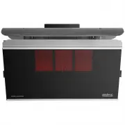
User Manual Bromic BH0920001-1


Summary
2 bromic.com ! IMPORTANT INSTRUCTIONS This manual contains important information about the installation, operation, and maintenance of Eclipse Smart-Heat TM Electric Heaters. Please pay close attention to the important safety information shown throughout this instruction manual. Any safety informati...
3 bromic.com CONTENT IMPORTANT NOTES & WARNINGS 4-5 PRODUCT OVERVIEW 6 PRODUCT DESCRIPTION 6 SPECIFICATIONS 6 PRODUCT FEATURES 6 KEY DIMENSIONS & CLEARANCES 7 INSTALLATION INSTRUCTIONS - CEILING MOUNTED HEATER 8-14 BOX CONTENTS 8-9 WARNING 9 INSTRUCTIONS FOR SINGLE POLE OPTIONS 10-11 INSTRUC...
4 bromic.com IMPORTANT NOTES & WARNINGS WARNING • IMPORTANT - Installation MUST be carried out by a licensed electrical contractor. • Heater must be installed by 2 persons. • Improper installation, adjustment, or alteration and failure to follow the warnings and instructions in this manual could...
Bromic Heaters Manuals
-
 Bromic 260631
User Manual
Bromic 260631
User Manual
-
 Bromic 2620240
User Manual
Bromic 2620240
User Manual
-
 Bromic 2620245
User Manual
Bromic 2620245
User Manual
-
 Bromic 2620247
User Manual
Bromic 2620247
User Manual
-
 Bromic 2620248
User Manual
Bromic 2620248
User Manual
-
 Bromic 2620251
User Manual
Bromic 2620251
User Manual
-
 Bromic 2620252
User Manual
Bromic 2620252
User Manual
-
 Bromic 2620253
User Manual
Bromic 2620253
User Manual
-
Bromic 2620254
User Manual
-
 Bromic 2620632
User Manual
Bromic 2620632
User Manual
-
 Bromic 2620634
User Manual
Bromic 2620634
User Manual
-
 Bromic 2620635
User Manual
Bromic 2620635
User Manual
-
 Bromic 2620636
User Manual
Bromic 2620636
User Manual
-
 Bromic 2620970
User Manual
Bromic 2620970
User Manual
-
 Bromic 2620980
User Manual
Bromic 2620980
User Manual
-
 Bromic 2620130-1PK
User Manual
Bromic 2620130-1PK
User Manual
-
 Bromic 2620131-1PK
User Manual
Bromic 2620131-1PK
User Manual
-
 Bromic 2620140-1PK
User Manual
Bromic 2620140-1PK
User Manual
-
 Bromic 2620141-1PK
User Manual
Bromic 2620141-1PK
User Manual
-
 Bromic 2620262-1
User Manual
Bromic 2620262-1
User Manual