Page 2 - PUBLICATION INFORMATION; SAMSUNG ELECTRONICS Co.
PUBLICATION INFORMATION SAMSUNG ELECTRONICS Co. reserves the right to revise information in this publication for any reason without prior notice. SAMSUNG ELECTRONICS Co. also reserves the right to make changes in equipment design or components as engineering and manufacturing may warrant without pri...
Page 4 - TECHNICAL MANUAL
NX-SERIES N X-3 0 8 N X-8 2 0 N X-1 2 3 2 ELECTRONIC KEY/HYBRID TELEPHONE SYSTEM TECHNICAL MANUAL INCLUDES : GEN ERA L D ESCRI PTI O N SECTI O N I N STA LLATI O N SECTI O N FEATU RE SECTI O N PRO GRA M M I N G SECTI O N A PPEN D I X SECTI O N BA CK-U P D ATA SH EETS 0preface 1999.9.15 12:46 PM 페이지3
Page 8 - TABLE OF CONTENTS; GENERAL DESCRIPTION
TABLE OF CONTENTS GENERAL DESCRIPTION NX-SERIES GENERAL SYSTEM DIAGRAM . . . . . . . . . . . . . . . . . 1-1 1. SYSTEM OVERVIEW . . . . . . . . . . . . . . . . . . . . . . . . . . . . . . . . 1-2 1.1 NX-308 SYSTEM . . . . . . . . . . . . . . . . . . . . . . . . . . . . . . . . . . . . 1-2 1.2 NX-820...
Page 10 - NX-SERIESGENERAL SYSTEM DIAGRAM
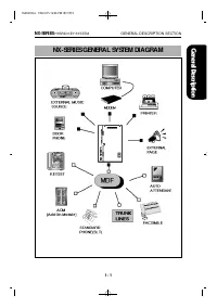
NX-SERIESGENERAL SYSTEM DIAGRAM NX-SERIES HYBRID KEY SYSTEM GENERAL DESCRIPTION SECTION 1 - 1 1G E NE R A L 1999.9.15 12:46 PM 페이지5
Page 13 - SYSTEM CONFIGURATION
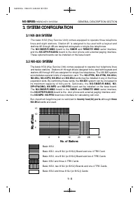
3. SYSTEM CONFIGURATION 3.1 NX-308 SYSTEM The basic KSU (Key Service Unit) comes equipped to operate three telephonelines and eight stations. Station #1 is assigned to be used with a keyset andstations #2 through #8 are assigned as keysets or single-line telephones.The NX-SMDR/R-MMC board is the SMD...
Page 15 - HARDWARE DESCRIPTION
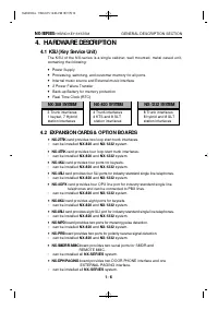
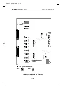
4. HARDWARE DESCRIPTION 4.1 KSU (Key Service Unit) The KSU of the NX-series is a single cabinet, wall mounted, metal cased unit,containing the following: ● Power Supply ● Processing, switching, and customer memory for all ports. ● Internal music source and External music interface ● 2 Power Failure ...
Page 16 - STATION EQUIPMENT
4.3 STATION EQUIPMENT ● Keyset with 24 buttons (NX-24E, NX-24B) ▷ Built-in speakerphone ▷ 24 programmable soft keys (12 with tri-colored LEDs) and 10 fixed-function keys ▷ UP/DOWN buttons for digital control of speaker, handset, and ringer volumes. ▷ Four selectable ring tones per keyset ▷ Desk- or ...
Page 17 - SPECIFICATIONS; ELECTRICAL SPECIFICATIONS
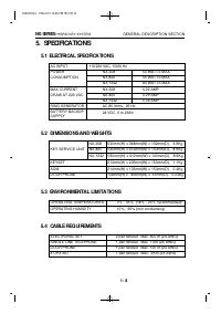
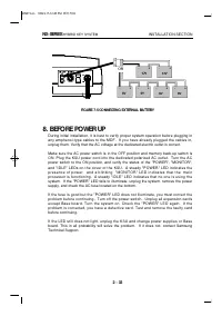
5. SPECIFICATIONS 5.1 ELECTRICAL SPECIFICATIONS AC INPUT 110/220 VAC, 50/60 Hz POWER NX-308 50 WATTS MAX CONSUMPTION NX-820 55 WATTS MAX NX-1232 80 WATTS MAX MAX CURRENT NX-308 0.22 AMP DRAW AT 220 VAC NX-820 0.29 AMP NX-1232 0.36 AMP RING GENERATOR AC 80 Vrms, 25 Hz BATTERY BACKUP 24 VDC, 6 to 26Ah...
Page 18 - SYSTEM TONES AND RINGS
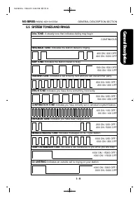
5.5 SYSTEM TONES AND RINGS DIAL TONE : A steady tone that indicates dialing may begin CONTINUOUS RING-BACK TONE : Indicates the station dialed is ringing. 400 ON / 200 OFF/ 400 ON / 3000 OFF BUSY TONE: Indicates the station dialed is busy. 500 ON / 500 OFF/ 500 ON / 500 OFF TRANSFER TONE: Indicates ...
Page 19 - KEYSET LED INDICATIONS
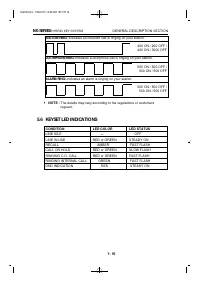
STATION RING: Indicates an intercom call is ringing on your station. 400 ON / 200 OFF /400 ON / 3000 OFF DOORPHONE RING: Indicates a doorphone call is ringing on your station. 500 ON / 500 OFF / 500 ON / 500 OFF ALARM RING: Indicates an alarm is ringing on your station. 500 ON / 500 OFF / 500 ON / 5...
Page 24 - BOARDS
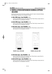
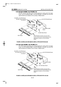
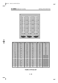
3. INSTALLATION EXPANSION CARDS & OPTION BOARDS Unpack and inspect each card before installing. Check for signs of physical damage. If any damage is detected, do not attempt to install. 3.1 NX-2TRK Card ( See FIGURE 3 - 1 ) Insert the NX-2TRK Card into any expansion slot. Push firmly to ensure t...
Page 32 - CONNECTING TELEPHONE LINES; SAFETY PRECAUTIONS; LOOP START LINES; CONNECTING STATION EQUIPMENT
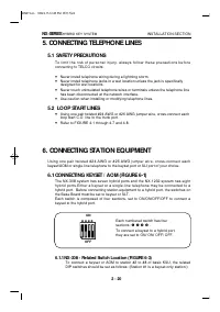
5. CONNECTING TELEPHONE LINES 5.1 SAFETY PRECAUTIONS T o l i m i t t h e r i s k o f p e r s o n a l i n j u r y , a l w a y s f o l l o w t h e s e p r e c a u t i o n s b e f o r econnecting to TELCO circuits: ● Never install telephone wiring during a lightning storm. ● Never install telephone jac...
Page 39 - -3 HOW TO REMOVE THE HANDSET CORD FROM THE HANDSET; Driver
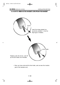
9-3 HOW TO REMOVE THE HANDSET CORD FROM THE HANDSET NX-SERIES HYBRID KEY SYSTEM INSTALLATION SECTION 2 - 34 Driver Line holder Insert the sharp-edged one(ex:driver, pincette,...) into theslight gap of handset. Slightly push the driver, and liftup the line holder from handset. Now, you have removed t...
Page 42 - FEATURES
TABLE OF CONTENTS FEATURES 1. FEATURE DESCRIPTIONS . . . . . . . . . . . . . . . . . . . . . . . . . . . . 3-1 1.1 SYSTEM FEATURES . . . . . . . . . . . . . . . . . . . . . . . . . . . . . . . . 3-1 1.2 STATION FEATURES . . . . . . . . . . . . . . . . . . . . . . . . . . . . . . . . 3-16 1.3 DISPLAY...
Page 43 - NOTICE
NX-SERIES HYBRID KEY SYSTEM FEATURES SECTION NOTICE this manual describes stadard setting. Some features, MMCCodes and default data may be different from those showndepending on the country. 3feature 1999.9.15 12:44 PM 페이지4
Page 44 - FEATURE DESCRIPTION
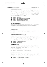
1. FEATURE DESCRIPTION 1.1 SYSTEM FEATURES ACCOUNT CODE (Voluntary)ALL CALL VOICE PAGEATTENTION TONEAUTHORIZATION CODES (Voluntary)AUTOMATIC HOLDBACKGROUND MUSICBATTERY BACKUP (Memory Protection)BATTERY BACKUP (System)CALL FORWARDING FORWARD ALL FORWARD BUSY FORWARD NO ANSWEREXTERNAL CALL FORWARD CA...
Page 50 - EXTERNAL MUSIC INTERFACE; FLEXIBLE NUMBERING; FLEXIBLE RINGING
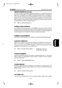
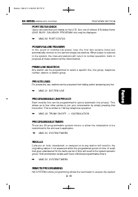
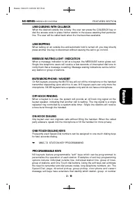
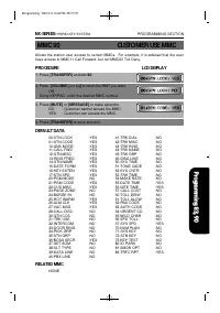
EXECUTIVE BARGE-IN (Override) The feature allows specially-programmed stations to override the automaticprivacy of another station. Programming provides three options: No Barge-in,With Tone, and Without Tone. When programmed without tone, the barging-inkeyset has its microphone muted. Each station c...
Page 59 - STATION FEATURES; AUTOMATIC HOLD
1.2 STATION FEATURES ADD-ON MODULE (AOM) MUTE MICROPHONE / HANDSET APPOINTMENT REMINDER OFF-HOOK RINGING AUTOMATIC HOLD ON-HOOK DIALING AUTOMATIC PRIVACY ONE TOUCH DIALING KEYS BACKGROUND MUSIC PROGRAMMABLE KEYS BUSY STATION CALLBACK PROTECTION FROM BARGE-IN BUSY STATION INDICATION (BLF) PULLOUT DIR...
Page 60 - BUSY STATION CALLBACK; DOOR LOCK RELEASE; EXCLUSIVE HOLD
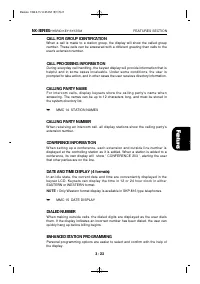
AUTOMATIC PRIVACY All conversations on outside lines and intercom calls are automatically private.The privacy feature can be turned off on a per-line basis. BACKGROUND MUSIC While the keyset is on-hook, the HOLD button alternately turns backgroundmusic (BGM) on or off. ➥ MMC 22 CUSTOMER ON/OFF ⇒ BGM...
Page 63 - RING MODES
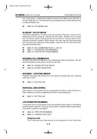
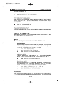
the feature key applies to. ➥ MMC 72 STATION KEY PROGRAMMING PROTECTION FROM BARGE-IN Each station can be programmed as either secure or not secure. Secure stationscannot be barged-in on. A not secure station talking to a secure station cannotbe barged-in on. ➥ MMC 24 ASSIGN BARGE-IN PULL-OUT DIRECT...
Page 65 - DISPLAY FEATURES; ACCOUNT CODE DISPLAY
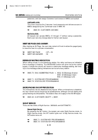
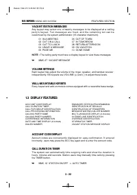
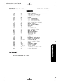
VACANT STATION MESSAGES Any keyset may select one of twenty messages to be displayed at a callingp a r t y ' s k e y s e t . T e n m e s s a g e s a r e f i x e d , a n d t h e r e m a i n i n g t e n c a n b ecustomized by the system administrator (16 character maximum). 01 IN A MEETING 06 OUT OF T...
Page 72 - PROGRAMMING
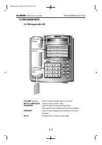
TABLE OF CONTENTS PROGRAMMING 1. INTRODUCTION TO PROGRAMMING ................................ 4-1 1.1 PROGRAMMING OVERVIEW ................................................... 4-1 1.2 PROGRAMMING LEVELS ......................................................... 4-1 1.3 PROGRAM KEYS ......................
Page 74 - INTRODUCTION TO PROGRAMMING; PROGRAMMING OVERVIEW; PROGRAMMING LEVELS; SYSTEM LEVEL; CUSTOMER LEVEL
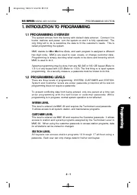
1. INTRODUCTION TO PROGRAMMING 1.1 PROGRAMMING OVERVIEW The system arrives from the factory with default data entered. Connect it totrunks, stations, and power, turn the system on and it is fully operational. Theonly thing left to do is customize the data to fit the customer's needs. This iscalled p...
Page 77 - PROGRAMMING PROCEDURES; PROGRAM LIST IN NUMERICAL ORDER
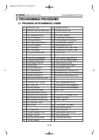
2. PROGRAMMING PROCEDURES 2.1 PROGRAM LIST IN NUMERICAL ORDER 00: STATION LOCK 45: TRUNK GROUP 01: CHANGE STATION PASSCODE 46: ASSIGN DISA LINE 10: SET ANSWER MODE 50: SYSTEM TIMERS 11: CALL FORWARD 51: TONE/RING CADENCE 12: STATION ON/OFF 52: SYSTEM WIDE COUNTER 13: SET RING FREQUENCY 53: TRUNK WID...
Page 78 - PROGRAM LIST IN ALPHABETICAL ORDER
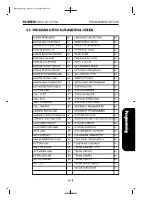
2.2 PROGRAM LIST IN ALPHABETICAL ORDER ALARM REMINDER 26 LANGUAGE SELECTION 93 ASSIGN ADD-ON MODULE 37 MAKE/BREAK RATIO 54 ASSIGN AUTO NIGHT TIME 56 OPEN PROGRAMMING 20 ASSIGN BARGE-IN 24 OVERRIDE TABLE 64 ASSIGN BOSS/SECRETARY 36 PAGE ZONE 23 ASSIGN DISA LINE 46 PBX ACCESS CODE 62 ASSIGN DOOR RING ...
Page 79 - PROGRAM PROCEDURES; OR
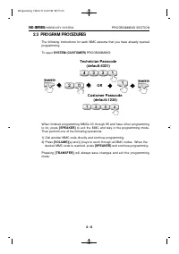
2.3 PROGRAM PROCEDURES The following instructions for each MMC assume that you have already openedprogramming. To open SYSTEM (CUSTOMER) PROGRAMMING: When finished programming MMCs 00 through 95 and have other programmingto do, press [SPEAKER] to exit the MMC and stay in the programming mode.Then pe...
Page 80 - PROCEDURE; STATION LOCK
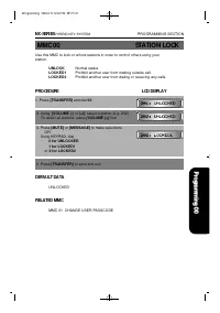
Use this MMC to lock or unlock stations in order to control others using your station. UNLOCK Normal status LOCKED1 Prohibit another user from making outside call. LOCKED2 Prohibit another user from dialing or receiving any calls. PROCEDURE LCD DISPLAY 1. Press [TRANSFER] and dial 00 2. Using [VOLUM...
Page 81 - CHANGE STATION PASSCODE
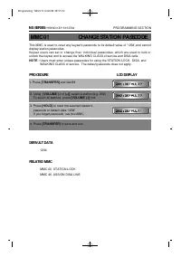
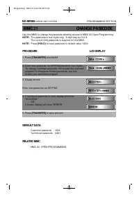
MMC 01 CHANGE STATION PASSCODE This MMC is used to reset any keyset's passcode to its default value of '1234',and cannotdisplay station passcodes. Keyset users can set or change their individual passcodes, which are used to lock orunlock the keyset and to access the WALKING CLASS of service and DISA...
Page 82 - SET ANSWER MODE; DEFAULT DATA; RELATED MMC
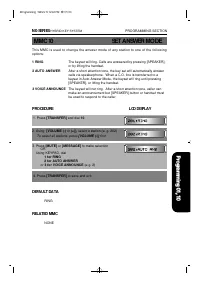
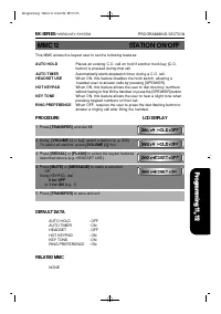
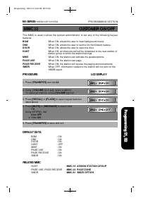
NX-SERIES HYBRID KEY SYSTEM PROGRAMMING SECTION MMC 10 SET ANSWER MODE This MMC is used to change the answer mode of any station to one of the followingoptions: 1 RING The keyset will ring. Calls are answered by pressing [SPEAKER], or by lifting the handset. 2 AUTO ANSWER After a short attention ton...
Page 83 - CALL FORWARD
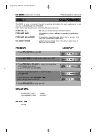
This MMC is used to program the call forwarding destination for each station and to setthe time for FORWARD NO ANSWER. Each station can forward calls under the following condition. FORWARD ALL All calls are forwarded to destination station FORWARD BUSY If the station is busy, calls are forwarded to ...
Page 85 - PPROCEDURE; LCD DISPLAY; SET RING FREQUENCY
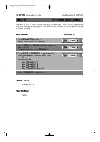
This MMC is used to select the ring frequency at each keyset. There are four types of ringfrequency available at each keyset. A sample of the selection can be heard when a dialkey pad is pressed. PPROCEDURE LCD DISPLAY 1. Press [TRANSFER] and dial 13 Display shows current ring frequency 2. Using [RE...
Page 86 - STATION NAMES
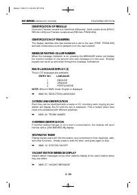
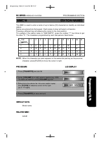
This MMC is used to enter a name of up to twelve (12) characters to identify an individualstation. Names are entered via the keypad. Each press of a key will select a character. Pressing a different key will advance the cursor to the next position.For example if the station name is "SAM SMITH�...
Page 87 - DATA DISPLAY
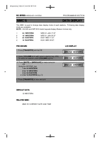
This MMC is used to change date display mode of each stations. Following date displaymode are available. NOTE: AS-30S and SKP-816 model keysets display Western format only. 1 24 WESTERN WED 21 JUN 17:37 2 12 WESTERN WED 21 JUN 05:37 3 24 EASTERN 06/21 WED 17:37 4 12 EASTERN 06/21 WED 05:37 PROCEDURE...
Page 88 - KEY EXTENDER
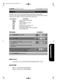
This MMC is used to view the programmable keys assigned to a keyset station. It also allows the system administrator to assign key extenders to some keys to make afeature key more specific. The feature keys accept extenders are: FEATURE KEY EXTENDER FWE External Call Forward(00~99) SPEED Dial (00~99...
Page 90 - OPEN PROGRAMMING
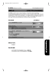
This MMC is used to open or close Customer or Technician level programming. If programming is not opened and an attempt is made to access a system MMC, the errormessage [NOT PERMIT] will be displayed. A four-digit Customer passcode is required toaccess Customer level programming allocated in MMC 90 ...
Page 91 - CHANGE PASSCODE
Use this MMC to change the passcode allowing access to MMC 20 'Open Programming'. NOTE: The passcode is four digits long. A digit may be 0 to 9. The current (old) passcode is required for this MMC. NOTE: Press [HOLD] to reset passcode to default value '1234'. PROCEDURE LCD DISPLAY 1. Press [TRANSFER...
Page 93 - PAGE ZONE
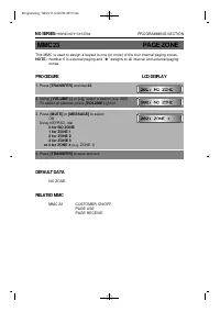
This MMC is used to assign a keyset to one (or none) of the four internal paging zones. NOTE: Number 5 is external paging and ' ✱ ' assigns to all internal and external paging zones. PROCEDURE LCD DISPLAY 1. Press [TRANSFER] and dial 23 2. Using [VOLUME (-) or (+)], select a station (e.g. 202) To se...
Page 96 - ALARM REMINDER
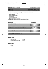
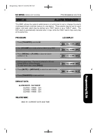
This MMC allows the system administrator or technician to set or change the alarmclock/appointment reminder feature for any station. Three alarms may be set for eachstation, and each alarm may be defined as a "DAY" alarm or as a "DAILY" alarm. TheDAY alarm is automatically canceled a...
Page 97 - VACANT MESSAGE
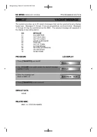
The system provides up to 20 vacant messages that can be selected by any displaykeyset user. Messages 01 through 10 are pre-programmed, as shown below. Messages11 through 20 may be customized via this MMC. The selected message will appeared inthe display of any calling station. NO. MESSAGE 01 IN A M...
Page 98 - CALL DISC
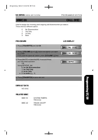
Used to assign the incoming and outgoing call disconnection per station.There are four different option. 0 No Disconnection1 Out Only2 In Only3 Both PROCEDURE LCD DISPLAY 1. Press [TRANSFER] and dial 28 2. Using [VOLUME (-) or (+)], select the station you want (e.g. 202)If you want to select all sta...
Page 99 - STATION TOLL CLASS
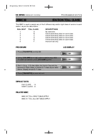
This MMC is used to assign any of the 6 different day and/or night class of service to eachstation, as per the table below: DIAL DIGIT TOLL CLASS DESCRIPTIONS 1 A No restriction 2 B Follow allow/deny table for each class 3 C Follow allow/deny table for each class 4 D Follow allow/deny table for each...
Page 101 - INTERCOM USE
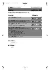
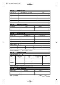
This MMC is used to allow/disallow station intercom calls. PROCEDURE LCD DISPLAY 1. Press [TRANSFER] and dial 32 2. Use [VOLUME (-) or (+)], to select a station (e.g. 202) To select all stations, press [VOLUME (-)] first 3. Press [REDIAL] or [FLASH] to select call station (e.g. ALL)To select all sta...
Page 102 - ASSIGN DOOR RING
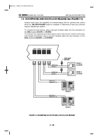
This MMC is used to designate which devices (station or station group) will ring when adoor box button is pressed. PROCEDURE LCD DISPLAY 1. Press [TRANSFER] and dial 33 Display shows designated stations or station groups for DOOR1 (day and night) 2. Press [VOLUME (-) or (+)] to select DOOR 1 or DOOR...
Page 103 - ASSIGN PICKUP GROUP
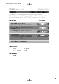
This MMC is used to allow the assignment of stations to call pickup groups. There may be a maximum 10 pickup groups (0~9). An unlimited number of members canbelong to each group. Stations can be in only one pickup group at any given time. PROCEDURE LCD DISPLAY 1. Press [TRANSFER] and dial 34 Display...
Page 104 - ASSIGN STATION GROUP
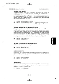
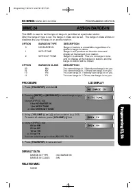
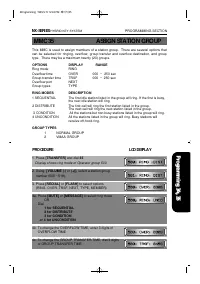
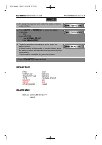
This MMC is used to assign members of a station group. There are several options thatcan be selected for ringing, overflow, group transfer and overflow destination, and grouptype. There may be a maximum twenty (20) groups. OPTIONS DISPLAY RANGE Ring mode RING Overflow time OVER 000 ~ 250 sec Group t...
Page 106 - ASSIGN BOSS/SECRETARY
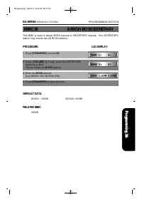
This MMC is used to assign BOSS keysets to SECRETARY keysets. One SECRETARYstation may include two (2) BOSS stations. PROCEDURE LCD DISPLAY 1. Press [TRANSFER] and dial 36 2. Using [VOLUME (-) or (+)], select the SECRETARY station (e.g. 202)Display shows the BOSS stations 3. Enter the BOSS stations ...
Page 107 - ASSIGN ADD-ON MODULE
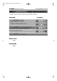
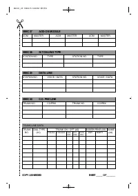
This MMC is used to assign an add-on module (AOM) to a station. PROCEDURE LCD DISPLAY 1. Press [TRANSFER] and dial 37 Display shows the first AOM port If there is no AOM port, display shows: 2. Press [VOLUME (-) or (+)], to select the AOM port To clear any previous entry, press [HOLD] 3. Enter maste...
Page 108 - SLT DIALING TYPE
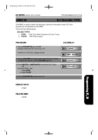
This MMC is used to define the dial type of phone connected to each SLT port. Keysets are not affected by this MMC. There are two dialing types: DIALING TYPES 1 DTMF Dual Tone Multi-Frequency (Touch Tone)2 PULSE Dial Pulse (rotary) PROCEDURE LCD DISPLAY 1. Press [TRANSFER] and dial 38 Display shows ...
Page 109 - DATA LINE
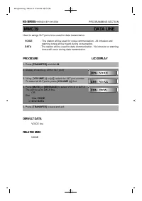
Used to assign SLT ports to be used for data transmission. VOICE - The station will be used for voice communication. All intrusion and warning tones will be heard during conversation. DATA - The station will be used for data communication. No intrusion or warning tones will occur during data transmi...
Page 111 - TRUNK DIALING TYPE
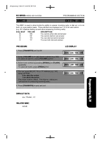
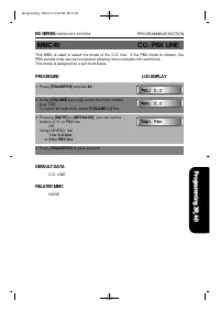
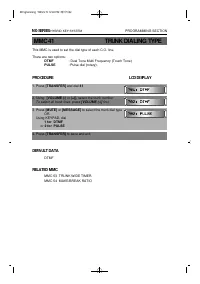
This MMC is used to set the dial type of each C.O. line. There are two options: DTMF : Dual Tone Multi Frequency (Touch Tone) PULSE : Pulse dial (rotary). PROCEDURE LCD DISPLAY 1. Press [TRANSFER] and dial 41 2. Using [VOLUME (-) or (+)], select the trunk number To select all trunk lines, press [VOL...
Page 113 - ASSIGN TRUNK RING
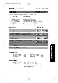
A trunk may have a maximum 16 members(station or station group) assigned to ring. PROCEDURE LCD DISPLAY 1. Press [TRANSFER] and dial 43 2. Using [VOLUME (-) or (+)], select the trunk you want (e.g., 703) 3. Press [REDIAL] or [FLASH], select the options (RING MODES, DAY MEMBERS or NIGHT MEMBERS) (e.g...
Page 114 - TRUNK NAMES
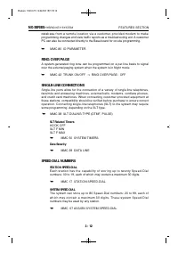
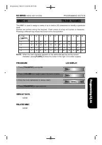
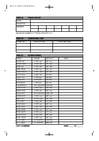
This MMC is used to assign a name of up to twelve (12) characters to identify a particulartrunk.N a m e s a r e w r i t t e n u s i n g t h e k e y p a d . E a c h p r e s s o f a k e y w i l l s e l e c t a c h a r a c t e r .Pressing a different key moves the cursor to the next position. NOTE : Wh...
Page 115 - TRUNK GROUP
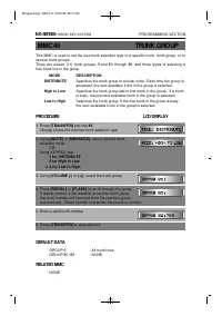
This MMC is used to set the free trunk selection type to a specific trunk, trunk group, or toseveral trunk groups. There are eleven (11) trunk groups: 9 and 80 through 89, and three types of selecting afree trunk line in the group. MODE DESCRIPTION DISTRIBUTE Searches the trunk group in circular ord...
Page 116 - ASSIGN DISA LINE
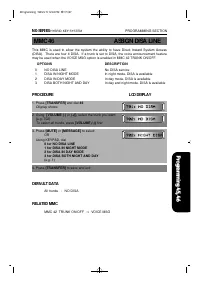
This MMC is used to allow the system the ability to have Direct Inward System Access(DISA). There are four 4 DISA. If a trunk is set to DISA, the voice announcement featuremay be used when the VOICE MSG option is enabled in MMC 42 TRUNK ON/OFF. OPTIONS DESCRIPTION 0 NO DISA LINE No DISA service 1 DI...
Page 117 - SYSTEM TIMERS
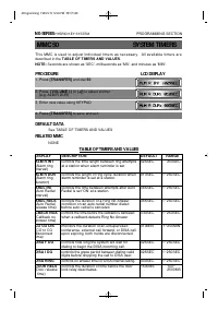
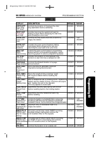
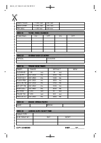
This MMC is used to adjust individual timers as necessary. All available timers aredescribed in the TABLE OF TIMERS AND VALUES. NOTE: Seconds are shown as 'SEC', milliseconds as 'MS', and minutes as 'MIN'. PROCEDURE LCD DISPLAY 1. Press [TRANSFER] and dial 50 2. Press [VOLUME (-) or (+)] to select a...
Page 120 - SYSTEM WIDE COUNTER
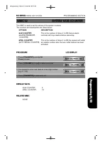
This MMC is used to set the values of the system counters. The counters and descriptions are listed below: OPTIONS DESCRIPTION ALM COUNTER This is the number of times (1 to 99) that an alarm (ALARM REMINDER reminder will ring a station before canceling. COUNTER) ARDL COUNTER This is the number of ti...
Page 121 - TRUNK WIDE TIMER
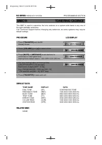
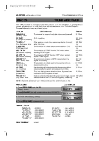
This MMC is used to changed trunk timer values. It is not advisable to change thesevalues, with exception of trunk flash time, without assistance from Technical Support.The available options are and listed below: DISPLAY DESCRIPTION RANGE CLEARING The interval for reuse of trunk after disconnecting ...
Page 122 - CURRENT DATA AND TIME
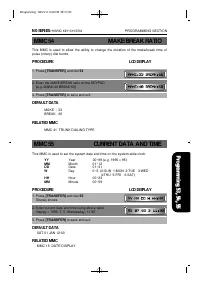
This MMC is used to allow the ability to change the duration of the make/break time ofpulse (rotary) dial trunks. PROCEDURE LCD DISPLAY 1. Press [TRANSFER] and dial 54 2. Enter the MAKE/BREAK ratio on the KEYPAD (e.g. MAKE:40 BREAK:60) 3. Press [TRANSFER] to save and exit DEFAULT DATA MAKE : 33BREAK...
Page 123 - ASSIGN AUTO NIGHT TIME
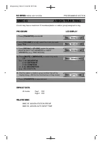
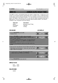
This MMC is used to automatically place the system in Night mode. A Night key is notneeded, as the system switches automatically, but it is helpful to have a dedicated buttonso the status can be changed manually. 'D' in the display is the time the system willswitch from Night to Day service and 'N' ...
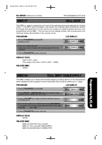
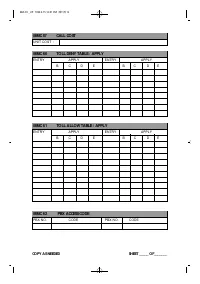
Page 124 - CALL COST
This MMC is used to program the unit cost of the metering pulse generated by the CentralOffice. If the MPD card is installed, it will detect the metering pulse provided by CentralExchange and determine the call cost by the number of metering pulses and unit costprogrammed via this MMC. The unit cost...
Page 125 - TOLL ALLOW TABLE/APPLY; PBX ACCESS CODE
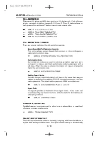
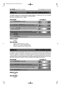
MMC 61 TOLL ALLOW TABLE/APPLY This MMC enables you to define which leading digit(s) in a dialing plan are to be allowedand which class(es) should be applied in this allow table. Each entry can define up to 11 digits. PROCEDURE LCD DISPLAY 1. Press [TRANSFER] and dial 61 2. Press [MUTE] or [MESSAGE] ...
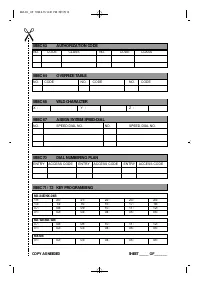
Page 126 - AUTHORIZATION TABLE
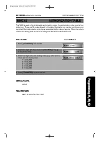
This MMC is used to list all allowable authorization codes. An authorization code must be fourdigits long. There are 50 codes allowed in this table. Duplications or number conflicts are notpermitted. Each authorization code has an associated dialing class of service. When the code isentered, the dia...
Page 127 - OVERRIDE TABLE
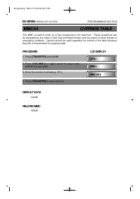
This MMC is used to enter up to five exceptions to toll restriction. These exceptions canbe accessed by any class in both Day and Night modes, and are useful to allow access toemergency numbers. Caution should be used regarding the entries of this table becausethey will not be blocked for outgoing c...
Page 128 - ASSIGN WILD CHARACTER
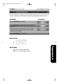
Provides flexibility to toll restriction when a specific numbering plan is desired. There areonly three entry tables, but more than one digit can be assigned per table if necessary. PROCEDURE LCD DISPLAY 1. Press [TRANSFER] and dial 65 2. Press [VOLUME (-) or (+)] to select the wild character (X,Y o...
Page 129 - SYSTEM SPD-DIAL TOLL RESTRICTION
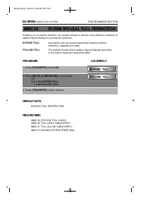
Enables you to define whether the system allows or denies long distance numbers insystem Speed-Dialing to override toll restriction. BYPASS TOLL Any station can use system speed dial numbers without restriction, regardless of class FOLLOW TOLL The system checks all the system Speed-Dialings accordin...
Page 130 - ASSIGN SYSTEM SPEED-DIAL
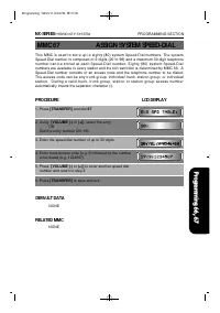
This MMC is used to store up to eighty (80) system Speed-Dial numbers. The systemSpeed-Dial number is composed of 2 digits (20 to 99) and a maximum 30-digit telephonen u m b e r c a n b e s t o r e d a t e a c h S p e e d - D i a l n u m b e r . E i g h t y ( 8 0 ) s y s t e m S p e e d - D i a lnum...
Page 131 - DIAL NUMBERING PLAN
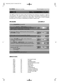
This MMC provides the access codes and dialing plan needed for operation of featuresand programs. The system comes with a wide range of acceptable numbering plans setas default, and the option to customize the dialing plan. There is also a confirm messageprovided due to the chance of duplicating an ...
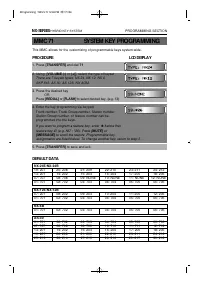
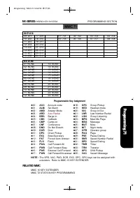
Page 133 - SYSTEM KEY PROGRAMMING
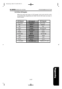
This MMC allows for the customizing of programmable keys system-wide. PROCEDURE LCD DISPLAY 1. Press [TRANSFER] and dial 71 2. Using [VOLUME (-) or (+)], select the type of keyset There are 7 keyset types: NX 24, NX 12, NX 6, SKP 816, AS 30, AS 12S, NX AOM. 3. Press the desired key OR Press [ R E D ...
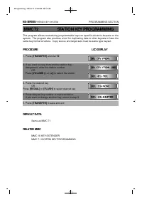
Page 135 - STATION KEY PROGRAMMING
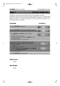
This program allows customizing programmable keys on specific electonic keysets on thesystem. The program also provides a tool for duplicating data to other keysets to have thesame key format structure. Copy source and target sets must be same type keyset. PROCEDURE LCD DISPLAY 1. Press [TRANSFER] a...
Page 136 - KEY TEST
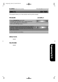
This program allows you to check whether each key works properly. PROCEDURE LCD DISPLAY 1. Press [TRANSFER] and dial 73 All LEDs light and station rings. Display sets show the full matrix pattern for 16 characters. All tri-color LEDs light amber 2. Press each function button and dial pad key to test...
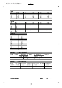
Page 137 - SYSTEM I/O PARAMETERS
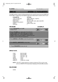
This MMC provides a means of setting parameters for the serial I/O ports to work with SMDR andRemote MMC. Programming is accomplished easily with the tables below to customize either I/O port. PARAMETER OPTIONS TYPE OF SERVICE SMDR, REMOTE, TRAFFIC REMOTE STN REMOTE only BAUD RATE 300, 600, 1200, 24...
Page 138 - SMDR OPTIONS
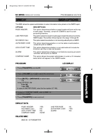
This MMC allows the system administrator to select information to be printed on the SMDR report. OPTIONS DESCRIPTIONS PAGE HEADER This option determines whether a page header will print at the topof each page. Normally turned off if SMDR is sent to a callaccounting machine. LINE PER PAGE This option...
Page 139 - CALL TRAFFIC REPORT
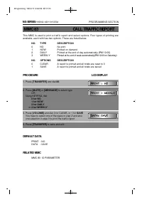
This MMC is used to print a traffic report and select options. Four types of printing areavailable, each with has two options. These are listed below: NO. TYPE DESCRIPTION 0 NO No print 1 NOW Printed on demand 2 DAILY Printed at the end of day automatically (PM 12:00) 3 WEEKLY Printed at the end of ...
Page 140 - CUSTOMER USE MMC
Allows the station user access to certain MMCs. For example, it is advised that the userhave access to MMC11 Call Forward, but not MMC60 Toll Deny. PROCEDURE LCD DISPLAY 1. Press [TRANSFER] and dial 90. 2. Press [VOLUME (-) o r ( + ) ] to select the MMC you want. OR Using KEYPAD, enter the desired M...
Page 141 - SYSTEM VERSION
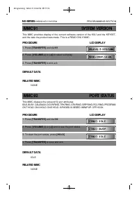
This MMC provides display of the current software version of the KSU and the KEYSET,and the date the product was made. This is a READ ONLY MMC. PROCEDURE LCD DISPLAY 1. Press [TRANSFER] and dial 91 2. Press [VOLUME (-) or (+)] to select a display 3. Press [TRANSFER] to and exit. DEFAULT DATA RELATED...
Page 142 - LANGUAGE SELECTION
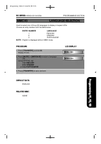
Used to select one of three (3) languages to display in keyset LCDs. Choose an entry number from the table below: ENTRY NUMBER LANGUAGE 1 ENGLISH 2 SPANISH 3 PORTUGUESE NOTE : English is displayed while in MMC mode. PROCEDURE LCD DISPLAY 1. Press [TRANSFER] and dial 93 Display shows... 2. Press [MUT...
Page 143 - HALT PROCESS
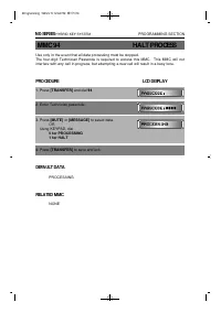
Use only in the event that all data processing must be stopped. The four-digit Technician Passcode is required to access this MMC. This MMC will notinterfere with any call in progress, but attempting a new call will result in a busy tone. PROCEDURE LCD DISPLAY 1. Press [TRANSFER] and dial 94 2. Ente...
Page 144 - SYSTEM RESTART
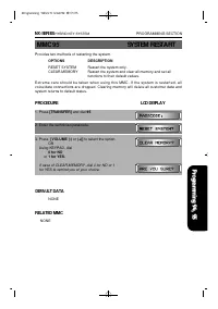
Provides two methods of restarting the system. OPTIONS DESCRIPTION RESET SYSTEM Restart the system only. CLEAR MEMORY Restart the system and clear all memory and set all functions to their default values. E x t r e m e c a r e s h o u l d b e t a k e n w h e n u s i n g t h i s M M C . I f t h e s y...
Page 146 - A. REMOTE PROGRAMMING
APPENDIX SECTION A. REMOTE PROGRAMMING B. DATABASE DOWNLOAD C. DISA VOICE ANNOUNCEMENT 5A PPE ND IX 1999.9.15 12:41 PM 페이지1
Page 148 - APPENDIX A; REMOTE PROGRAMMING; CUSTOMER SITE REQUIREMENTS
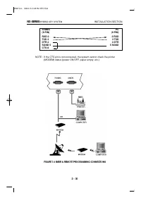
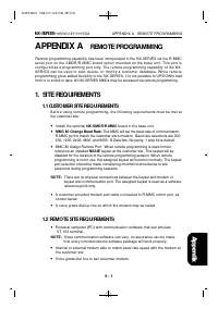
APPENDIX A REMOTE PROGRAMMING Remote programming capability has been incorporated in the NX-SERIES via the R-MMCserial port on the SMDR/R-MMC board option mounted on the base unit. This port isconfigured as a programming port only. The remote programming capability of the NX-SERIES can be used to ad...
Page 149 - BEGIN PROGRAMMING; PROGRMMING PROTOCOL
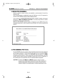
1.3 BEGIN PROGRAMMING Dial the customer modem number and establish a communication link with thecustomer site.Once communication is established, press the TAB key on the PC keyboard toreceive the NX-SERIES system header display (below). If you receive a "SORRY!DESTINATION PORT IS BUSY" displ...
Page 150 - BEGIN PROGRAMMING
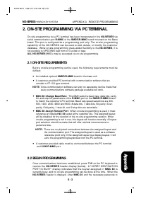
2. ON-SITE PROGRAMMING VIA PC TERMINAL On-site programming via a PC terminal has been incorporated in the NX-SERIES viaserial communication port R-MMC of the SMDR/R-MMC board mounted on the Baseboard. This port is configured as a programming port only. The on-site programmingcapability of the NX-SER...
Page 151 - PROGRAMMING PROTOCOL
open programming and begin the on-site programming session. NOTE: The header will display CUSTOMER and the name assigned in MMC 81. 2.3 PROGRAMMING PROTOCOL The NX-SERIES will only recognize keystrokes on the PC keyboard that havebeen assigned as NX 24 keyset equivalent. These keystrokes are fixed a...
Page 152 - APPENDIX B; DATABASE DOWNLOAD; Customer Site Requirements; Installing Database Downloading; Setup of Database Downloading Program; Starting NX Download Program
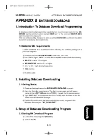
APPENDIX B DATABASE DOWNLOAD 1. Introduction To Database Download Programming A database download programming capability has been incorporated into the N X -S E R I E S via the communication (serial) SMDR port of the optional S M D R / R - M M Ccard mounted in the base unit.This is a software utilit...
Page 153 - Setup Of Database Downloading Program
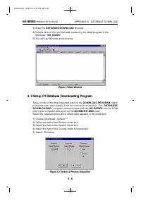
3) Enter the DATABASE DOWNLOAD directory. 4) Double-click on the icon that was created by the install program in the Windows -"NX_DOWN" 5) You will see Windows shown below. Figure 1.1 Main Window 3. 2 Setup Of Database Downloading Program Setup is one of the most important parts of the DOWNL...
Page 154 - Using database downloading program
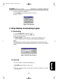
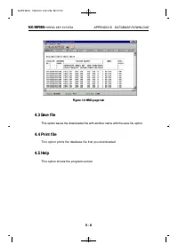
6) Choose Download / Serial Port*** 7) Check COM port in the Select serial port check box 8) Select OK button. Figure 1.3 Port dialog box 4. Using database downloading program 4.1 Downloading 1) Choose DOWNLOAD / Download to File***. 2) Input file name that will contain the MMC data. 3) Select Downl...
Page 156 - APPENDIX C; DISA VOICE ANOUNCEMENT
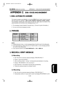
APPENDIX C DISA VOICE ANOUNCEMENT 1. DISA AUTOMATIC ANSWER The system answers automatically an incoming DISA (Direct Inward System Access)call and sends the message: "This is XXX company. Extension number, please". This facilitates handling your DISA calls and tells the calling party the sta...
Page 158 - DATA SHEETS
BACK-UP DATA SHEETS 6B A C K _ U P 1999.9.15 12:40 PM 페이지1
Page 160 - DATABASE FORMS
NX- _____________ SYSTEM DATABASE FORMS DATABASE CONTAINS _____________SHEETS CUSTOMER NAME : ADDRESS : TELEPHONE NUMBER : 6B A C K _ U P 1999.9.15 12:40 PM 페이지3
Page 162 - SYSTEM CONFIGURATION; STATION DATA
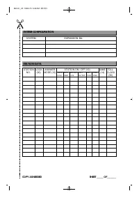
SYSTEM CONFIGURATION SYSTEM EXPANSION Bd. STATION DATA STATION LOCK ANSWER STATION ON / OFF (12) NAME TOLL NO. (00) MODE (10) AUTO AUTO HEADSET HOT KEY RING (14) CLASS HOLD TIMER USE KEYPAD TONE FREQ. (30) COPY AS NEEDED SHEET _____ OF_______ 6B A C K _ U P 1999.9.15 12:40 PM 페이지5