Page 2 - FRANÇAIS 3
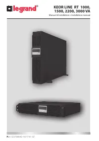
2 FRANÇAIS 3 ENGLISH 23 ITALIANO 43 DEUTSCH 63 ESPAÑOL 83 NEDERLANDS 103 PУСCKИЙ 123 FR EN KEOR LINE RT 1000, 1500, 2200, 3000 VA ® IT DE ES NL RU
Page 3 - Index
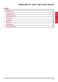
3 KEOR LINE RT 1000, 1500, 2200, 3000 VA FR Index 1 Introduction 4 2 Conditions d’utilisation 4 3 Afficheur 7 4 Panneau arrière 8 5 Installation 9 6 Logiciel 16 7 Maintenance 17 8 Caractéristiques techniques 20
Page 4 - Introduction; Conditions d’utilisation
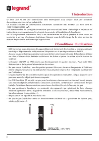
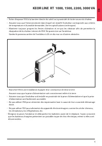
4 ® 1 Introduction Le Keor Line RT est une alimentation sans interruption (ASI) conçue pour une utilisation domestique, commercial ou industrielle. Ce manuel contient les informations concernant l’utilisation des modèles ASI Keor Line RT 1000,1500,2200,3000 kVA. Lire attentivement les consignes de s...
Page 6 - Stockage
6 ® 2 Conditions d’utilisation Stockage Si votre onduleur n’est pas utilisé pour une période prolongée assurez le stockage dans un climat modéré.Les batteries doivent être chargées pendent 12 heures tous les 2 mois en alimentant l’onduleur et en fermant l’interrupteur d’entrée. Répétez cette procédu...
Page 7 - Afficheur LCD
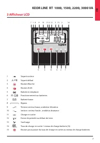
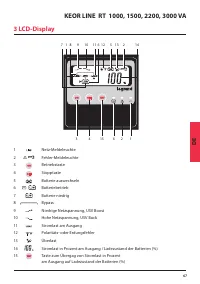
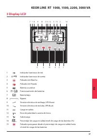
7 KEOR LINE RT 1000, 1500, 2200, 3000 VA FR 3 Afficheur LCD 7 1 8 9 10 11 6 12 5 13 2 14 3 4 15 6 2 1 1 Voyant secteur 2 Voyant défaut 3 Bouton Marche 4 Bouton Arrêt 5 Batterie à remplacer 6 Fonctionnement sur batteries 7 Batterie basse 8 Bypass 9 Tension secteur basse, onduleur élévateur 10 tension...
Page 8 - Panneau arrière
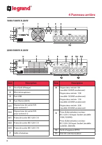
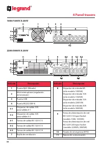
8 ® 1000/1500V A 230V 2200/3000V A 230V 4 Panneau arrière Item Description 1 Port Rj45 (filtrage) 2 Mini interrupteurs 3 Port USB 4 Port RS232 (DB-9) 5-1 Disjoncteur de sortie10A pour sorties 6-1 5-2 Disjoncteur de sortie10A pour sorties 6-2 6-1 Prises de sortie IEC-320-C13 6-2 Prises de sortie IEC-...
Page 9 - Déballage; Installation
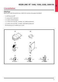
9 KEOR LINE RT 1000, 1500, 2200, 3000 VA FR Déballage Après avoir retiré les protections, vérifier les contenu du paquet standard: • 1 x ASI Keor Line RT• 1 x manuel de l’utilisateur• 1 x cordon d’alimentation• 1 x cordon de sortie IEC ( modèle 1k/1,5kVA seulement)• 2 x cordon de sortie IEC ( modèle...
Page 10 - Configuration Tour
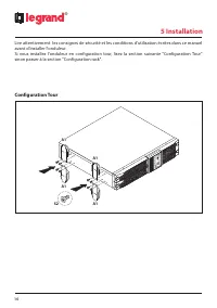
10 ® 5 Installation Lire attentivement les consignes de sécurité et les conditions d'utilisation écrites dans ce manuel avant d'installer l'onduleur. Si vous installez l'onduleur en configuration tour, lisez la section suivante "Configuration Tour" sinon passer à la section "Configuratio...
Page 11 - Configuration Rack
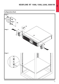
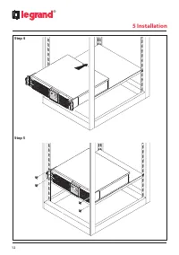
11 KEOR LINE RT 1000, 1500, 2200, 3000 VA FR Configuration Rack S2 S2 B1 B2 S3 B1 Step 1 Step 2 Step 3
Page 13 - Raccordement de l’ASI; ATTENTION; Connexion réseau
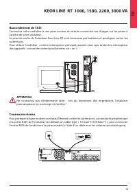
13 KEOR LINE RT 1000, 1500, 2200, 3000 VA FR Raccordement de l’ASI Connectez votre onduleur à une prise secteur et ensuite connectez vos charges sur les prises à l’arrière de votre onduleur. Le prise de sortie de l’onduleur Keor Line RT sont secourues par batteries et protégées contre les surtension...
Page 14 - MISE EN MARCHE; Arrêt de l’onduleur
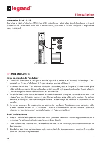
14 ® 5 Installation Connexion RS232 /USB Branchez le câble d’interface ( RS232 ou USB) entre le port situé à l’arrière de l’onduleur et le port d’interface de l’ordinateur. Pour plus d'informations, consultez la section « Logiciel » disponibles dans ce manuel. 5.1 MISE EN MARCHE Mise en marche de l’...
Page 16 - Logiciel; Communication; Broche Assignment Description
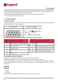
16 ® 6 Logiciel Vérifier la disponibilité et télécharger le logiciel de l'onduleur depuis le site web www.ups.legrand.com. Ce logiciel peut être utilisé pour les fonctions suivantes: - Arrêt automatique de l'ordinateur local connecté a l’onduleur par USB /RS232 - Lecture des paramètres de l’onduleur...
Page 17 - Maintenance de l’onduleur; Remplacement des batteries
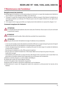
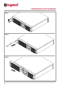
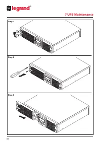
17 KEOR LINE RT 1000, 1500, 2200, 3000 VA FR 7 Maintenance de l’onduleur Remplacement des batteries Au démarrage de l’onduleur un test automatique est exécute. Le voyant de remplacement batteries peut s’allumer si une batterie est faible ou en fin de vie. 1. Lorsque le voyant de remplacement de batt...
Page 19 - Recyclage des batteries usagées
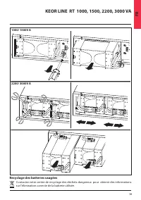
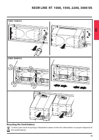
19 KEOR LINE RT 1000, 1500, 2200, 3000 VA FR 1000/ 1500V A 2200/ 3000V A Recyclage des batteries usagées Contactez votre centre de recyclage des déchets dangereux pour obtenir des informations sur l'élimination correcte de la batterie utilisée.
Page 20 - Caractéristique techniques; MODEL NUMBER
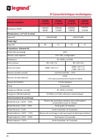
20 ® 8 Caractéristique techniques MODEL NUMBER 1000VA (3 100 45) 1500VA (3 100 46) 2200VA (3 100 47) 3000VA (3100 48) Puissance, VA/W 1000VA/ 900W 1500VA/ 1350W 2200VA/ 1980W 3000VA/ 2700W Dimensions, L x P x H, in (mm)Appareil 440x405x88 440x650x88 Poids (kg)Appareil 20 21 34 37 Paramètres d’entrée...
Page 24 - Condition of use
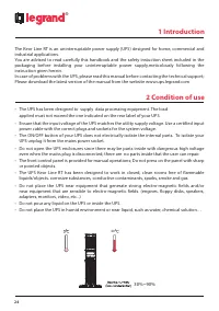
24 1 Introduction ® The Keor Line RT is an uninterruptable power supply (UPS) designed for home, commercial and industrial applications. You are advised to read carefully this handbook and the safety instuction sheet included in the packaging before installing your uninterruptable power supply,metic...
Page 26 - Storage
26 ® 2 Condition of use Storage If the UPS is unused for an extended period of time it must be stored in a moderate climate. The batteries should be charged for 12 hours every three months by connecting the UPS to the utility supply and switching on the input breaker located on the UPS rear panel. R...
Page 27 - LCD Display Panel
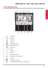
27 KEOR LINE RT 1000, 1500, 2200, 3000 VA EN 3 LCD Display Panel 1 Utility LED 2 Fault LED 3 On Switch 4 Off Switch 5 Battery Replacement 6 Battery Backup LED 7 Battery Low 8 Bypass 9 Utility Low, 10 UPS Boost 11 UPS Output Indicator 12 Polarity Error or Ground Fault 13 Overload 14 Load/Battery Leve...
Page 28 - Rear Panel; Item
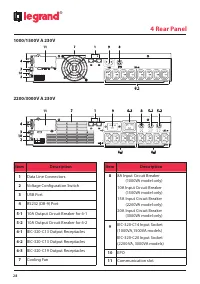
28 ® 1000/1500V A 230V 2200/3000V A 230V 4 Rear Panel Item Description 1 Data Line Connectors 2 Voltage Configuration Switch 3 USB Port 4 RS232 (DB-9) Port 5-1 10A Output Circuit Breaker for 6-1 5-2 10A Output Circuit Breaker for 6-2 6-1 IEC-320-C13 Output Receptacles 6-2 IEC-320-C13 Output Receptac...
Page 29 - Unpacking
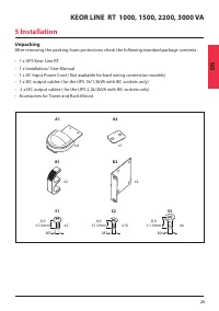
29 KEOR LINE RT 1000, 1500, 2200, 3000 VA EN Unpacking After removing the packing foam protections check the following standard package contents : • 1 x UPS Keor Line RT• 1 x Installation/ User Manual• 1 x AC Input Power Cord ( Not available for hard wiring connection models)• 1 x IEC output cables ...
Page 30 - Tower Setup
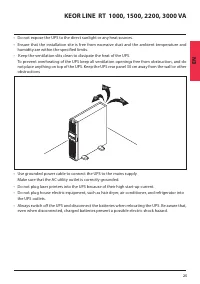
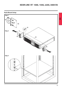
30 ® 5 Installation Please read the safety instructions and the conditions of use written in this manual before installing the UPS. If you are installing the UPS in its tower configuration, read the following section “Tower setup” otherwise go to the next section “Rack-Mount setup”. Tower Setup A1 A...
Page 33 - UPS connections; CAUTION; Network connection
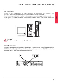
33 KEOR LINE RT 1000, 1500, 2200, 3000 VA EN UPS connections Connect the UPS to a grounded AC power wall outlet using the power cord included in the packaging.Then plug the loads into the outlets available on the rear of the UPS. The UPS outlets provide battery backup and surge protection to the equ...
Page 34 - Computer Interface Port connections
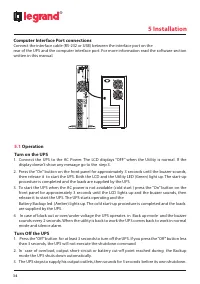
34 ® 5 Installation Computer Interface Port connections Connect the interface cable (RS-232 or USB) between the interface port on the rear of the UPS and the computer interface port. For more information read the software section written in this manual. 5.1 Operation Turn on the UPS 1. Connect the U...
Page 36 - UPS Software; Communication Port; DB-9 Pin Assignment Description
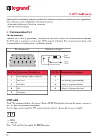
36 ® 6 UPS Software Please verify the availability and download the UPS software tool from the website www.ups.legrand.com. This software can be used for the following functions: - Automatic shutdown of the local computer - UPS parameters reading 6.1 Communication Port DB-9 Connector The UPS has a D...
Page 37 - UPS Maintenance; Battery Replacement
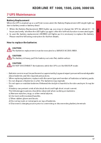
37 KEOR LINE RT 1000, 1500, 2200, 3000 VA EN 7 UPS Maintenance Battery Replacement When the UPS is started up or a self-test is executed, the Battery Replacement LED might light up due to battery weak or battery dead.1. When the Battery-Replacement (RED) lights up, you may re-charge the UPS for atle...
Page 39 - Recycling the Used battery
39 KEOR LINE RT 1000, 1500, 2200, 3000 VA EN 1000/ 1500V A 2200/ 3000V A Recycling the Used battery Contact your local recycling or hazardous waste center for information on proper disposal of the used battery.
Page 40 - Technical features
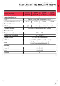
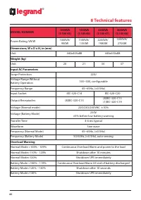
40 ® 8 Technical features MODEL NUMBER 1000VA (3 100 45) 1500VA (3 100 46) 2200VA (3 100 47) 3000VA (3 100 48) Power Rating, VA/W 1000VA/ 900W 1500VA/ 1350W 2200VA/ 1980W 3000VA/ 2700W Dimensions, W x D x H, in (mm)Unit 440x405x88 440x650x88 Weight (kg)Unit 20 21 34 37 Input AC ParametersSurge Prote...
Page 43 - Indice
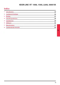
43 KEOR LINE RT 1000, 1500, 2200, 3000 VA IT Indice 1 Introduzione 44 2 Condizioni di utilizzo 44 3 Display 47 4 Pannello posteriore 48 5 Installazione 49 6 Software 56 7 Manutenzione 57 8 Caratteristiche tecniche 60
Page 44 - Introduzione; Condizioni di utilizzo
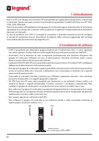
44 ® 1 Introduzione Keor Line RT è un Gruppo di Continuità (UPS) progettato per applicazioni domestiche, commerciali o industriali. Questo manuale contiene le informazioni riguardanti i modelli UPS Keor Line RT 1000, 1500, 2200, 3000 kVA. Prima di procedere all’installazione del gruppo di continuità...
Page 46 - Stoccaggio
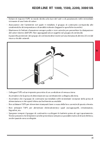
46 ® 2 Condizioni di utilizzo Stoccaggio In caso di inutilizzo per un periodo prolungato il gruppo di continuità deve essere conservato a temperatura moderata.Le batterie devono essere caricate per 12 ore ogni 2 mesi alimentando il gruppo di continuità e chiudendo l’interruttore di ingresso. Ripeter...
Page 47 - Display LCD
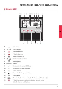
47 KEOR LINE RT 1000, 1500, 2200, 3000 VA IT 3 Display LCD 7 1 8 9 10 11 6 12 5 13 2 14 3 4 15 6 2 1 1 Spia di rete 2 Spia di guasto 3 Pulsante di marcia 4 Pulsante di arresto 5 Batteria da sostituire 6 Funzionamento a batterie 7 Batteria bassa 8 Bypass 9 Tensione di rete bassa, UPS Boost 10 Tension...
Page 48 - Pannello posteriore
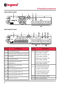
48 ® 1000/1500V A 230V 2200/3000V A 230V 4 Pannello posteriore Item Descrizione 1 Porta Rj45 (filtraggio) 2 Mini interruttori (regolazione tensione) 3 Porta USB 4 Porta RS232 (DB-9) 5-1 Disgiuntore di uscita 10A per uscite 6-1 5-2 Disgiuntore di uscita 10A per uscite 6-2 6-1 Prese di uscita IEC-320-...
Page 49 - Disimballaggio; Installazione
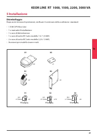
49 KEOR LINE RT 1000, 1500, 2200, 3000 VA IT Disimballaggio Dopo avere rimosso le protezioni, verificare il contenuto della confezione standard: • 1 X Kit UPS Keor Line• 1 x manuale d’installazione• 1 x cavo d’alimentazione • 1 x cavo d’uscita IEC (solo modello 1 k / 1,5 kVA) • 2 x cavo d’uscita IEC...
Page 50 - Configurazione Tower
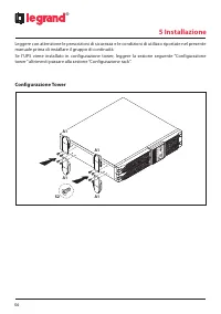
50 ® 5 Installazione Leggere con attenzione le prescrizioni di sicurezza e le condizioni di utilizzo riportate nel presente manuale prima di installare il gruppo di continuità. Se l’UPS viene installato in configurazione tower, leggere la sezione seguente “Configurazione tower” altrimenti passare al...
Page 51 - Configurazione Rack
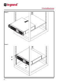
51 KEOR LINE RT 1000, 1500, 2200, 3000 VA IT Configurazione Rack S2 S2 B1 B2 S3 B1 Fase 1 Fase 2 Fase 3
Page 53 - Collegamento dell’UPS; ATTENZIONE; Connessione di rete
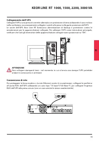
53 KEOR LINE RT 1000, 1500, 2200, 3000 VA IT Collegamento dell’UPS Collegare l'UPS a una presa di corrente alternata con protezione di terra utilizzando il cavo incluso nella confezione, successivamente collegate i carichi alla prese nella parte posteriore dell’UPS. Le uscite dell’UPS Keor Line RT f...
Page 54 - Connessione RS232 /USB; MESSA IN FUNZIONE; Arresto dell’UPS
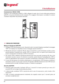
54 ® 5 Installazione Connessione RS232 /USB Tramite il cavo d’interfaccia (RS232 o USB) collegare la porta che si trova nella parte posteriore dell’UPS e la porta d’interfaccia del computer. Per maggiori informazioni consultare la sezione “Software” disponibile nel presente manuale. 5.1 MESSA IN FUN...
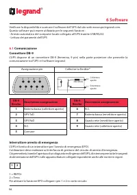
Page 56 - Software; Comunicazione; Broche Descrizione assegnazione
56 ® 6 Software Verificare la disponibilità e scaricare il software dell’UPS dal sito web www.ups.legrand.com. Questo software può essere utilizzato per le seguenti funzioni : - Arresto automatico del computer locale collegato all’UPS tramite USB/RS232 - Lettura dei parametri dell’UPS 6.1 Comunicazi...
Page 57 - Manutenzione del gruppo di continuità; Sostituzione delle batterie
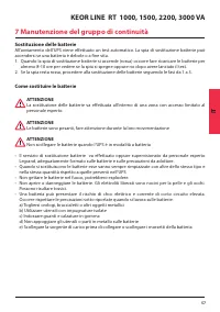
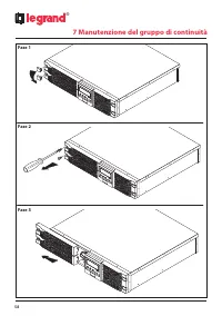
57 KEOR LINE RT 1000, 1500, 2200, 3000 VA IT 7 Manutenzione del gruppo di continuità Sostituzione delle batterie All’avviamento dell’UPS viene effettuato un test automatico. La spia di sostituzione batterie può accendersi se una batteria è debole o a fine vita. 1. Quando la spia di sostituzione batt...
Page 59 - Smaltimento delle batterie usate
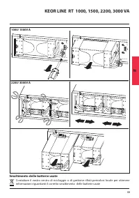
59 KEOR LINE RT 1000, 1500, 2200, 3000 VA IT 1000/ 1500V A 2200/ 3000V A Smaltimento delle batterie usate Contattare il vostro centro di riciclaggio o di gestione rifiuti pericolosi locale per ottenere informazioni riguardanti il corretto smaltimento delle batterie usate
Page 60 - Caratteristiche tecniche; NUMERO MODELLO
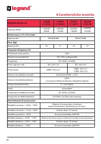
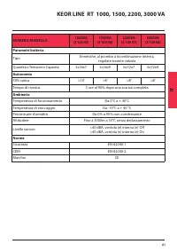
60 ® 8 Caratteristiche tecniche NUMERO MODELLO 1000VA (3 100 45) 1500VA (3 100 46) 2200VA (3 100 47) 3000VA (3100 48) Potenza, VA/W 1000VA/ 900W 1500VA/ 1350W 2200VA/ 1980W 3000VA/ 2700W Dimensioni, L x P x H in (mm)Apparecchio 440x405x88 440x650x88 Peso (kg)Apparecchio 20 21 34 37 Parametri d’ingre...
Page 63 - Inhaltsverzeichnis
63 DE KEOR LINE RT 1000, 1500, 2200, 3000 VA 1 Einleitung 44 2 Anwendungsbedingungen 44 3 Display 47 4 Hintere Tafel 48 5 Installation 49 6 Software 56 7 Wartung der unterbrechungsfreien Stromversorgung 57 8 Technische Daten 60 Inhaltsverzeichnis
Page 64 - Einleitung; Anwendungsbedingungen
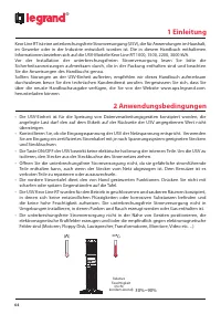
64 ® 1 Einleitung Keor Line RT ist eine unterbrechungsfreie Stromversorgung (USV), die für Anwendungen im Haushalt, im Gewerbe oder in der Industrie entwickelt worden ist. Die in diesem Handbuch enthaltenen Informationen beziehen sich auf die USV-Modelle Keor Line RT 1000, 1500, 2200, 3000 kVA. Vor ...
Page 66 - Lagerung
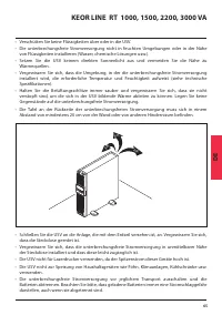
66 ® 2 Anwendungsbedingungen Lagerung Falls die unterbrechungsfreie Stromversorgung längere Zeit nicht verwendet wird, diese bei mäßiger Temperatur lagern.Die Batterien müssen alle 2 Monate 12 Stunden lang aufgeladen werden. Dabei muss die unterbrechungsfreie Stromversorgung gespeist und der Eingang...
Page 68 - Hintere Tafel; Beschreibung; 1 Kommunikations-Slot
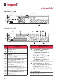
68 ® 1000/1500V A 230V 2200/3000V A 230V 4 Hintere Tafel Art. Beschreibung 1 Port Rj45 (Filter) 2 Mini-Schalter (Spannungsregelung) 3 USB-Port 4 Port RS-232 (DB-9) 5-1 Trennschalter am Ausgang 10A für Ausgänge 6-1 5-2 Trennschalter am Ausgang 10A für Ausgänge 6-2 6-1 Ausgangsbuchsen IEC-320-C13 6-2 ...
Page 69 - Auspacken
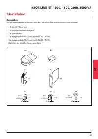
69 KEOR LINE RT 1000, 1500, 2200, 3000 VA DE Auspacken Die Schutzelemente entfernen und den Inhalt der Standardpackung kontrollieren: • 1 X Set USV Keor Line• 1 x Installationsanweisungen• 1 x Speisekabel • 1 x Ausgangskabel IEC (nur Modell 1 k / 1,5 kVA)• 2 x Ausgangskabel IEC (nur Modell 2,2 k / 3...
Page 72 - Phase 4
Page 73 - ACHTUNG; Netzanschlüsse
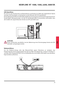
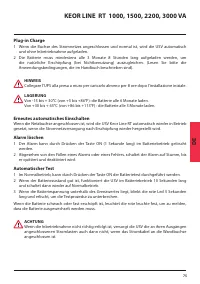
73 KEOR LINE RT 1000, 1500, 2200, 3000 VA DE USV-Anschluss Die USV an eine Strombuchse mit Wechselstrom und Erdung mit Hilfe des mitgelieferten Kabels und dann die Stromlasten an die Buchsen an der Rückseite der USV anschließen. Die Ausgänge der USV Keor Line RT liefern die Notstromversorgung und Sc...
Page 74 - INBETRIEBNAHME; USV ausschalten
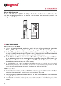
74 ® 5 Installation RS232 /USB Anschluss Das Kabel der Schnittstelle (RS232 oder USB) an den Port an der Rückseite der USV und an den Port des Computers anschließen. Für weitere Informationen, siehe Abschnitt „Software“ im vorliegenden Handbuch. 5.1 INBETRIEBNAHME Inbetriebnahme der USV 1 Die USV an...
Page 76 - Kommunikation; Broche Beschreibung der Zuteilung
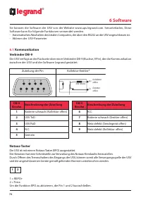
76 ® 6 Software Sie können die Software der USV von der Website www.ups.legrand.com. herunterladen, Diese Software kann für folgende Funktionen verwendet werden: - Automatisches Abschalten des lokalen Computers, der über den RS232 an die USV angeschlossen ist. - Ablesen der USV-Parameter 6.1 Kommuni...
Page 77 - Wartung der unterbrechungsfreien Stromversorgung; Batterien auswechseln
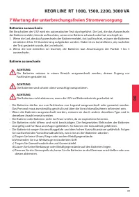
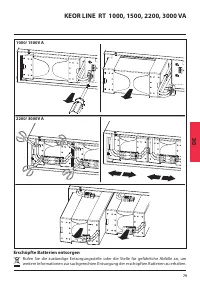
77 KEOR LINE RT 1000, 1500, 2200, 3000 VA DE 7 Wartung der unterbrechungsfreien Stromversorgung Batterien auswechseln Bei Einschalten der USV wird ein automatischer Test durchgeführt. Die Led, die das Auswechseln der Batterie meldet, könnte aufleuchten, wenn eine Batterie schwach oder fast erschöpft...
Page 78 - Phase 1
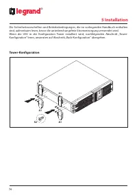
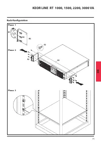
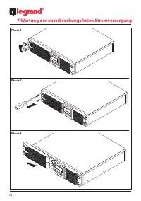
78 ® 7 Wartung der unterbrechungsfreien Stromversorgung Phase 1 Phase 2 Phase 3
Page 79 - Erschöpfte Batterien entsorgen
79 KEOR LINE RT 1000, 1500, 2200, 3000 VA DE 1000/ 1500V A 2200/ 3000V A Erschöpfte Batterien entsorgen Rufen Sie die zuständige Entsorgungsstelle oder die Stelle für gefährliche Abfälle an, um weitere Informationen zur sachgerechten Entsorgung der erschöpften Batterien zu erhalten.
Page 80 - Technische Daten; MODELLNUMMER
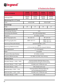
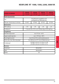
80 ® 8 Technische Daten MODELLNUMMER 1000VA (3 100 45) 1500VA (3 100 46) 2200VA (3 100 47) 3000VA (3100 48) Leistung, VA/W 1000VA/ 900W 1500VA/ 1350W 2200VA/ 1980W 3000VA/ 2700W Abmessung (H x L x T) (mm)Gerät 440x405x88 440x650x88 Gewicht (kg)Gerät 20 21 34 37 Eingangsparameter NOSchutz gegen Überl...
Page 83 - Tabla de contenidos
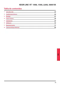
83 KEOR LINE RT 1000, 1500, 2200, 3000 VA ES Tabla de contenidos 1 Introducción 64 2 Condiciones de uso 64 3 Display 67 4 Panel trasero 68 5 Instalación 69 6 Software 76 7 Mantenimiento 77 8 Características técnicas 80
Page 84 - Introducción; Condiciones de uso
84 ® 1 Introducción Keor Line RT es un Grupo de Continuidad (SAI) diseñado para aplicaciones domésticas, comerciales o industriales. Este manual contiene la información relativa a los modelos SAI Keor Line RT 1000, 1500, 2200, 3000 kVA. Antes de proceder a la instalación del grupo de continuidad lee...
Page 86 - Almacenamiento
86 ® 2 Condiciones de uso Almacenamiento En caso de inutilización durante un período prolongado, el grupo de continuidad tiene que conservarse a una temperatura moderada.Las baterías tienen que cargarse durante 12 horas cada 2 meses alimentando el grupo de continuidad y cerrando el interruptor de en...
Page 88 - Panel trasero; Artículo
88 ® 1000/1500V A 230V 2200/3000V A 230V 4 Panel trasero Artículo Descripción 1 Puerto Rj45 (filtrado) 2 Mini-interruptores (regulación de la tensión) 3 Puerto USB 4 Puerto RS232 (DB-9) 5-1 Disyuntor de salida 10A para salidas 6-1 5-2 Disyuntor de salida 10A para salidas 6-2 6-1 Tomas de salida IEC-...
Page 89 - Desembalaje; Instalación
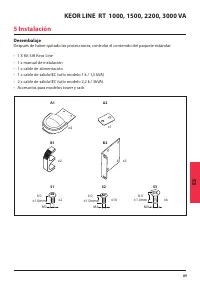
89 KEOR LINE RT 1000, 1500, 2200, 3000 VA ES Desembalaje Después de haber quitado las protecciones, controlar el contenido del paquete estándar: • 1 X Kit SAI Keor Line• 1 x manual de instalación• 1 x cable de alimentación• 1 x cable de salida IEC (sólo modelo 1 k / 1,5 kVA)• 2 x cable de salida IEC...
Page 90 - Configuración Tower
90 ® 5 Instalación Leer con atención las prescripciones de seguridad y las condiciones de uso que se encuentran en el presente manual antes de instalar el grupo de continuidad. Si el SAI se instala en configuración tower, leer la sección siguiente “Configuración tower”; de lo contrario pasar a la se...
Page 91 - Configuración Rack
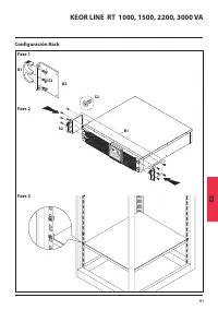
91 KEOR LINE RT 1000, 1500, 2200, 3000 VA ES Configuración Rack S2 S2 B1 B2 S3 B1 Fase 1 Fase 2 Fase 3
Page 93 - Conexión del SAI; ATENCIÓN; Conexión de red
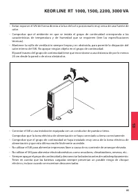
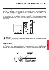
93 KEOR LINE RT 1000, 1500, 2200, 3000 VA ES Conexión del SAI Conectar el SAI a una toma de corriente alterna con protección de tierra utilizando el cable que se incluye en el paquete; sucesivamente conectar las cargas a las tomas de corriente que se encuentran en la parte trasera del SAI. Las salid...
Page 94 - Puesta en función; Parada del SAI
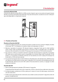
94 ® 5 Instalación Conexión RS232/USB A través del cable de interfaz (RS232 o USB) conectar el puerto que se encuentra en la parte trasera del SAI y el puerto de interfaz del ordenador. Para más información consultar la sección “Software” que está disponible en el presente manual. 5.1 Puesta en func...
Page 96 - Comunicación; Polo
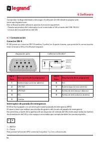
96 ® 6 Software Comprobar la disponibilidad y descargar el software del SAI desde la página web www.ups.legrand.com. Este software puede utilizarse para las funciones siguientes: - Parada automática del ordenador local conectado al SAI a través del USB/ RS232. - Lectura de los parámetros del SAI. 6....
Page 97 - Mantenimiento del SAI; Sustitución de las baterías
97 KEOR LINE RT 1000, 1500, 2200, 3000 VA ES 7 Mantenimiento del SAI Sustitución de las baterías En el momento del arranque del SAI, se realiza una prueba automática. El indicador luminoso de sustitución de las baterías puede encenderse si una batería es débil o ha alcanzado la terminación de su vid...
Page 99 - Eliminación de las baterías usadas
99 KEOR LINE RT 1000, 1500, 2200, 3000 VA ES 1000/ 1500V A 2200/ 3000V A Eliminación de las baterías usadas Contactar el centro de reciclaje o de gestión de residuos peligrosos local para obtener información acerca de la eliminación correcta de las baterías usadas.
Page 100 - Características técnicas; NÚMERO DE MODELO
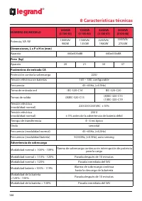
100 ® 8 Características técnicas NÚMERO DE MODELO 1000VA (3 100 45) 1500VA (3 100 46) 2200VA (3 100 47) 3000VA (3100 48) Potencia, VA /W 1000VA/ 900W 1500VA/ 1350W 2200VA/ 1980W 3000VA/ 2700W Dimensiones, L x P x H in (mm)Aparato 440x405x88 440x650x88 Peso (kg)Aparato 20 21 34 37 Parámetros de entra...
Page 104 - Inleiding; Gebruiksvoorwaarden
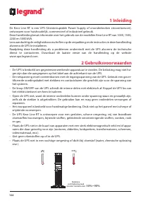
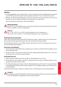
104 ® 1 Inleiding De Keor Line RT is een UPS (Uninterruptable Power Supply of ononderbroken stroomtoevoer), ontworpen voor huishoudelijk, commercieel of industrieel gebruik. Deze handleiding bevat informatie over het gebruik van de modellen Keor Line RT van 1000, 1500, 2200 en 3000 kVA. Lees aandach...
Page 106 - Opslag
106 ® 2 Gebruiksvoorwaarden Opslag Bewaar de UPS op een plaats met een gematigd klimaat als u hem gedurende langere periode niet gebruikt.Laad de batterijen om de drie maanden op gedurende 12 uur, door de UPS te voeden en de in- gangsschakelaar te sluiten, die zich bevind op het acterpaneel. Herhaal...
Page 108 - Achterpaneel
108 ® 1000/1500V A 230V 2200/3000V A 230V 4 Achterpaneel Item Beschrijving 1 Data lijn aansluiting RJ45-poort (filter) 2 Voltage configuratie micro switches 3 USB-poort 4 RS232-poort (DB-9) 5-1 Uitgangsautomaat 10A voor uitgangen 6-1 5-2 Uitgangsautomaat 10A voor uitgangen 6-2 6-1 Uitgangscontactdoz...
Page 109 - Uitpakken; Installatie
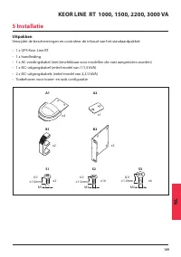
109 KEOR LINE RT 1000, 1500, 2200, 3000 VA NL Uitpakken Verwijder de beschermingen en controleer de inhoud van het standaardpakket: • 1 x UPS Keor Line RT• 1 x handleiding• 1 x AC voedingskabel (niet beschikbaar voor modellen die vast aangesloten worden)• 1 x IEC-uitgangskabel (enkel model van 1/1,5...
Page 110 - Installeren als tower
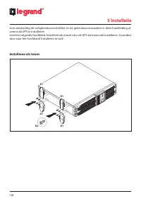
110 ® 5 Installatie Lees aandachtig de veiligheidsvoorschriften en de gebruiksvoorwaarden in deze handleiding al- vorens de UPS te installeren. Lees het volgende hoofdstuk ‘Installeren als tower’ als u de UPS als tower wilt installeren. Ga anders door naar het hoofdstuk ‘Installeren in rack’. Instal...
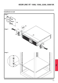
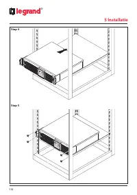
Page 111 - Installeren in rack
111 KEOR LINE RT 1000, 1500, 2200, 3000 VA NL Installeren in rack S2 S2 B1 B2 S3 B1 Stap 1 Stap 2 Stap 3
Page 113 - De UPS aansluiten; OPGELET; Netwerkaansluiting
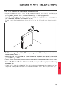
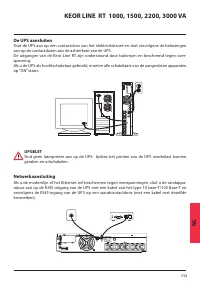
113 KEOR LINE RT 1000, 1500, 2200, 3000 VA NL De UPS aansluiten Sluit de UPS aan op een contactdoos van het elektriciteitsnet en sluit vervolgens de belastingen aan op de contactdozen aan de achterkant van de UPS. De uitgangen van de Keor Line RT zijn ondersteund door batterijen en beschermd tegen o...
Page 114 - Computer interface poort aansluitingen
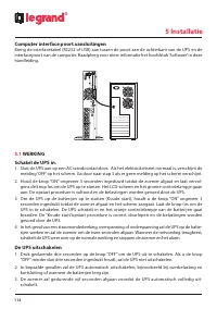
114 ® 5 Installatie Computer interface poort aansluitingen Breng de interfacekabel (RS232 of USB) aan tussen de poort aan de achterkant van de UPS en de interfacepoort van de computer. Raadpleeg voor meer informatie het hoofdstuk ‘Software’ in deze handleiding. 5.1 WERKING Schakel de UPS in. 1. Slui...
Page 116 - Communicatie poort; Pin
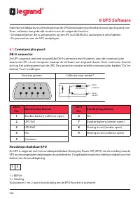
116 ® 6 UPS Software Indien beschikbaar kunt u de software van de UPS downloaden op de website www.ups.legrand.com. Deze software kan gebruikt worden voor de volgende functies: - De plaatselijke pc die is aangesloten op de UPS via USB/RS232 automatisch uitschakelen. - De parameters van de UPS raadpl...
Page 117 - Onderhoud van de UPS; De batterijen vervangen
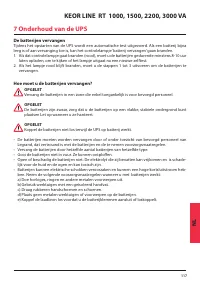
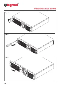
117 KEOR LINE RT 1000, 1500, 2200, 3000 VA NL 7 Onderhoud van de UPS De batterijen vervangen Tijdens het opstarten van de UPS wordt een automatische test uitgevoerd. Als een batterij bijna leeg is of aan vervanging toe is, kan het controlelampje ‘batterij vervangen’ gaan branden. 1. Als dat controle...
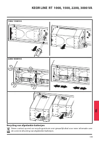
Page 119 - Recycling van afgedankte batterijen
119 KEOR LINE RT 1000, 1500, 2200, 3000 VA NL 1000/ 1500V A 2200/ 3000V A Recycling van afgedankte batterijen Neem contact op met uw recyclingcentrum voor gevaarlijk afval voor meer informatie over de correcte afvoering van afgedankte batterijen.
Page 120 - Technische kenmerken; MODELNUMMER
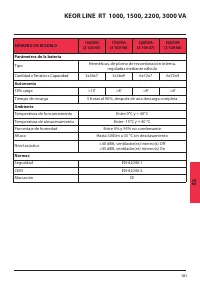
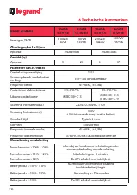
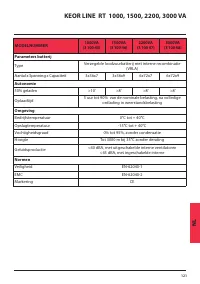
120 ® 8 Technische kenmerken MODELNUMMER 1000VA (3 100 45) 1500VA (3 100 46) 2200VA (3 100 47) 3000VA (3100 48) Vermogen, VA/W 1000VA/ 900W 1500VA/ 1350W 2200VA/ 1980W 3000VA/ 2700W Afmetingen, L x B x H (mm)Apparaat 440x405x88 440x650x88 Gewicht (kg)Apparaat 20 21 34 37 Parameters van AC-ingangOver...
Page 123 - Содержание
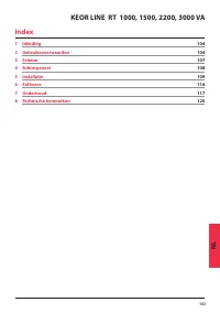
RU 123 Содержание ИБП KEOR LINE RT 1000, 1500, 2200, 3000 1 Введение 124 2 Меры безопасности 124 3 Панель управления с ЖК дисплеем 127 4 Задняя панель 128 5 Монтаж 129 6 Программное обеспечение ИБП 136 7 Техническое обслуживание ИБП 137 8 Технические характеристики 140
Page 124 - Введение; Меры безопасности
124 ® 1 Введение Keor Line RT – это источник бесперебойного питания (ИБП) бытового, коммерческого и промышленного назначения. Перед тем, как приступать к монтажу ИБП, настоятельно рекомендуется внимательно изучить требования настоящего руководства и тщательно следовать приведённым в нём инструкциям....
Page 126 - Правила хранения; Хранение
126 ® 2 Правила хранения Хранение Длительное хранение ИБП разрешается при умеренной температуре. Батареи следует заряжать в течение 12 часов каждые 12 месяцев, подключив ИБП к электросети и включив вводной выключатель на задней панели ИБП. При температуре хранения более 25 °C повторяйте эту процедур...
Page 127 - Панель управления с ЖК дисплеем
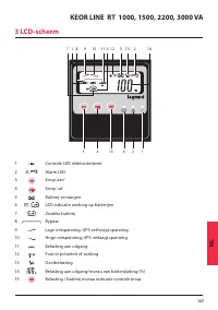
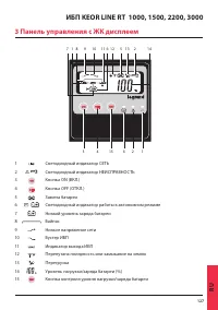
RU 127 ИБП KEOR LINE RT 1000, 1500, 2200, 3000 3 Панель управления с ЖК дисплеем 7 1 8 9 10 11 6 12 5 13 2 14 3 4 15 6 2 1 1 Светодиодный индикатор СЕТЬ 2 Светодиодный индикатор НЕИСПРАВНОСТЬ 3 Кнопка ON (ВКЛ.) 4 Кнопка OFF (ОТКЛ.) 5 Замена батареи 6 Светодиодный индикатор работы в автономном режиме...
Page 128 - Задняя панель; Поз
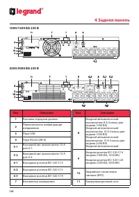
128 ® 1000/1500 ВА 230 В 2200/3000 ВА 230 В 4 Задняя панель Поз Описание 1 Разъемы передачи данных 2 Переключатель конфигурации напряжения 3 Порт USB 4 Порт RS232 (DB-9) 5-1 Выходной авт. выключатель 10 А для 6-1 5-2 Выходной авт. выключатель 10 А для 6-2 6-1 Выходные розетки IEC-320-C13 6-2 Выходны...
Page 129 - Распаковка; Монтаж
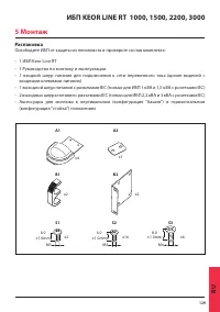
RU 129 ИБП KEOR LINE RT 1000, 1500, 2200, 3000 Распаковка Освободите ИБП от защиты из пенопласта и проверьте состав комплекта: • 1 ИБП Keor Line RT• 1 Руководство по монтажу и эксплуатации• 1 входной шнур питания для подключения к сети переменного тока (кроме моделей с входными клеммами питания) • 1...
Page 130 - Монтаж в вертикальном положении
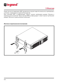
130 ® 5 Монтаж Перед тем как устанавливать ИБП, внимательно изучите меры безопасности и требования к установке, содержащиеся в данном Руководстве. При установке ИБП в конфигурации "башня" изучите требования раздела "Монтаж в вертикальном положении". При установке ИБП в конфигурации &...
Page 131 - Монтаж в горизонтальном положении
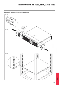
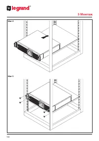
RU 131 ИБП KEOR LINE RT 1000, 1500, 2200, 3000 Монтаж в горизонтальном положении S2 S2 B1 B2 S3 B1 Шаг 1 Шаг 2 Шаг 3
Page 133 - Подключение ИБП; Защита устройств локальной сети
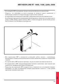
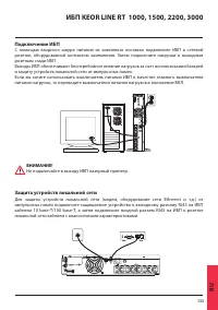
RU 133 ИБП KEOR LINE RT 1000, 1500, 2200, 3000 Подключение ИБП С помощью входного шнура питания из комплекта поставки подключите ИБП к сетевой розетке, оборудованной контактом заземления. Затем подключите нагрузки к выходным розеткам сзади ИБП. Выходы ИБП обеспечивают бесперебойное питание нагрузок ...
Page 134 - Подключение к портам компьютера; Работа с ИБП
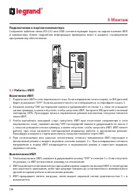
134 ® 5 Монтаж Подключение к портам компьютера Соедините кабелем связи (RS-232 или USB) соответствующие порты на задних панелях ИБП и компьютера. Более подробная информация приведена ниже в разделе, посвященном программному обеспечению. 5.1 Работа с ИБП Включение ИБП 1 Подключите ИБП к сети переменн...
Page 136 - Программное обеспечение ИБП; Порт связи; No конт. Назначение и описание
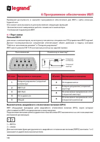
136 ® 6 Программное обеспечение ИБП Проверьте доступность и скачайте программное обеспечение для ИБП с сайта www.ups. legrand.com. Оно может использоваться для выполнения следующих функций: -Автоматическое завершение работы локального компьютера -Считывание параметров ИБП 6.1 Порт связи Разъем DB-9 ...
Page 137 - Техническое обслуживание ИБП; Замена батареи
RU 137 ИБП KEOR LINE RT 1000, 1500, 2200, 3000 7 Техническое обслуживание ИБП Замена батареи Светодиодный индикатор "Замена батареи" может загореться при запуске или самотестировании ИБП, если батарея не держит заряд или вышла из строя. 1. Если загорается красный светодиодный индикатор "...
Page 139 - Утилизация использованных батарей
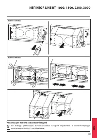
RU 139 ИБП KEOR LINE RT 1000, 1500, 2200, 3000 1000/1500 ВА 2200/3000 ВА Утилизация использованных батарей По поводу утилизации использованных батареи обратитесь в соответствующую организацию по месту эксплуатации.
Page 140 - Технические характеристики; НОМЕР МОДЕЛИ
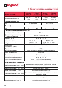
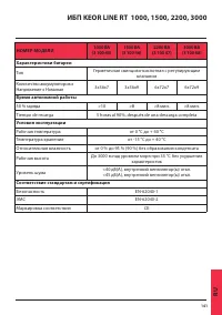
140 ® 8 Технические характеристики НОМЕР МОДЕЛИ 1000 ВА (3 100 45) 1500BA (3 100 46) 2200BA (3 100 47) 3000BA (3100 48) Номинальная мощность 1000 ВА/ 900 Вт 1500 ВА/ 1350 Вт 2200 ВА/ 1980 Вт 3000 ВА/ 2700 Вт Размеры, Ш x Г x В (мм)ИБП 440 x 405 x 88 440 x 650 x 88 Масса (кг)ИБП 20 21 34 37 Характери...
Page 142 - Notes