Jet 708599K - User Manual
Jet 708599K Grinding Machine – User Manual, read for free online in PDF format. We hope this helps you resolve any issues you may have. If you have further questions, please contact us through the contact form.


Table of Contents:
- Page 2 – Warranty and Service
- Page 3 – Table of Contents
- Page 4 – not
- Page 7 – On/Off Switch Padlock
- Page 8 – Grounding Instructions; This adapter is not applicable in Canada.
- Page 9 – Extension Cords; Recom m ended M inim um Gauge (A WG ) of E xtension C ords
- Page 10 – Unpacking; Contents of Main Carton
- Page 11 – Contents of Closed Stand Carton:; Contents of Open Stand Carton:
- Page 12 – Assembly; Machine is heavy! Use; Disc Table
- Page 13 – Abrasive Disc
- Page 14 – Abrasive Belt; Workstop Assembly
- Page 15 – Dust Collection; Adjustments; Belt Table Adjustment
- Page 16 – Belt Arm Orientation
- Page 17 – Miter Gauge
- Page 18 – Before doing maintenance on
- Page 19 – Troubleshooting; Trouble Probable; Optional Accessories
- Page 21 – Parts List for JSG-6DC Belt/Disc Sander Assembly; Descript ion
- Page 26 – Electrical Connections
Operating Instructions and Parts Manual
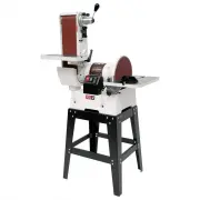
Combination Belt/Disc Sander
Model JSG-6DC
wi th opti onal open stand
wi th opti onal cl osed stand
WALTER MEIER (Manufacturing) Inc.
427 New Sanford Road
LaVergne, Tennessee 37086
Part No. M-708598
Ph.: 800-274-6848
Revision G
03/2010
www.waltermeier.com
Copyright © 2010 Walter Meier (Manufactur ing) Inc.
This .pdf document is bookmarked
"Loading the manual" means you need to wait until the file loads and becomes available for online reading. Some manuals are very large, and the time they take to appear depends on your internet speed.
Summary
2 Warranty and Service Walter Meier (Manufacturing) Inc., warrants every product it sells. If one of our tools needs service or repair, one of our Authori zed Service Centers located throughout the United States can give you quick service. In most cases, any of these Walter Meier Authorized Service ...
3 Table of Contents Warranty and Ser vice..........................................................................................................................2 Table of Contents ........................................................................................................................
4 Warni ng 1. Read and understand t he entire owner’s manual before attempting assembly or operation. 2. Read and understand t he war nings posted on t he machine and in this manual. Failure to comply wit h all of these warnings may cause serious injury. 3. Replace t he warning labels if they become...