Page 2 - Wallplate installation; CAUTION: ELECTRICAL HAZARD
69-2815EFS—03 2 LEVEL HERE M34819 CK Rc R W- O/B YG W2- Aux/E Y2L M34500A Wallplate installation 1. Separate wallplate from thermostat. 2. Mount wallplate as shown below. Drill 3/16" holes for drywall. Drill 7/32" holes for plaster. Wall anchors Wallplate Wire hole Mounting screws CAUTION: E...
Page 3 - Terminal Designations; Wiring; R and Rc
3 69-2815EFS—03 C Common wire from secondary side of cooling transformer (if 2 transformers). K Optional wirer save module. Rc Cooling power. Connect to secondary side of cooling system transformer. R Heating power. Connect to secondary side of heating system transformer. W-O/B 1st stage heat relay....
Page 4 - Wiring guide — conventional systems; NOTES; Wiring Instructions; Jumper Loop
69-2815EFS—03 4 1H/1C System (1 transformer) Rc Power [1] R [R+Rc joined by jumper loop] Y Compressor contactor C 24VAC common W Heat relay G Fan relay Heat-only System Rc Power [1] R [R+Rc joined by jumper loop] C 24VAC common W Heat relay 1H/1C System (2 transformers) Rc Power (cooling transformer...
Page 5 - Wiring guide — heat pump systems
5 69-2815EFS—03 1H/1C Heat Pump System Rc Power [1] R [R+Rc joined by jumper loop] Y Compressor contactor C 24VAC common O/B Changeover valve [7] G Fan relay 2H/1C Heat Pump System Rc Power [1] R [R+Rc joined by jumper loop] Y Compressor contactor C 24VAC common O/B Changeover valve [2] G Fan relay ...
Page 6 - Initial setup
69-2815EFS—03 6 Initial setup Upon initial power up, or after being reset to factory defaults, the initial thermostat options (language, location, and system type) must be set to define the heating/cooling system. Other options can be customized later.Follow prompts on the screen to select appropria...
Page 7 - System setup; Screen Title; From the home screen, touch; Menu; to modify the initial system setup.
7 69-2815EFS—03 System setup System Setup Options (MENU > System Setup) Screen Title Settings and Options Language English/Français/Español. Thermostat installed in Home/Business (Thermostat is used in a residential (default) or commercial setting). Your thermostat location Touch THERMOSTAT butto...
Page 8 - Connecting to the Wi-Fi network; Done
69-2815EFS—03 8 Connecting to the Wi-Fi network Yes Your Network Done Next Done Register online for remote access Press for info After the initial setup, walk the homeowner through connecting to a Wi-Fi network. Or, refer the homeowner to the User’s Guide, so the homeowner can connect the thermostat...
Page 9 - Setting advanced preferences
9 69-2815EFS—03 Setting advanced preferences 1 Touch MENU . The thermostat displays a list of options. 2 Select Preferences > Advanced Preferences . The thermostat displays the first screen of options that you can change. 3 On each screen, make changes as needed, then touch Next to display new op...
Page 10 - Troubleshooting; SYSTEM
69-2815EFS—03 10 Troubleshooting If you have difficulty with your thermostat, please try the following suggestions. Most problems can be corrected quickly and easily. Display is blank • Check circuit breaker and reset if necessary.• Make sure power switch at heating and cooling system is on.• Make s...
Page 11 - Accessories & replacement parts; Please contact your distributor to order replacement parts.; Specifications; Terminal
11 69-2815EFS—03 Accessories & replacement parts Please contact your distributor to order replacement parts. Cover plate assembly . . . . . . . . . . . . . . . . . Part Number THP2400A1027W Specifications Temperature Ranges • Heat: 40° to 90°F (4.5° to 32°C) • Cool: 50° to 99°F (10° to 37°C) Ope...
Page 12 - DISCONNECT POWER BEFORE INSTALLATION.
Automation and Control Systems Honeywell International Inc. 1985 Douglas Drive North Golden Valley, MN 55422 Honeywell Ltd 705 Montrichard Avenue Saint-Jean-sur-Richelieu, Québec J2X 5K8 http://customer.honeywell.com ® U.S. Registered Trademark.Apple, iPhone, iPad, iPod touch and iTunes are trademar...
Page 13 - Installation Guide; à écran; Conditions intérieures.
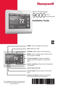
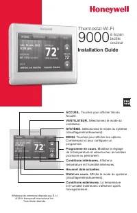
Installation Guide ® Marque de commerce déposée aux É.-U © 2014 Honeywell International Inc. Tous droits réservés. Thermostat Wi-Fi 9000 à écran tactile couleur ACCUEIL. Touchez pour afficher l’écran Accueil. VENTILATEUR. Sélectionnez le mode du ventilateur. SYSTÈME. Sélectionnez le mode du système ...
Page 14 - Installation de la plaque murale; MISE EN GARDE : RISQUE DE CHOC ÉLECTRIQUE
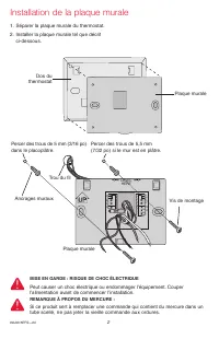
69-2815EFS—03 2 LEVEL HERE M34819 CK Rc R W- O/B YG W2- Aux/E Y2L M34500A Installation de la plaque murale 1. Séparer la plaque murale du thermostat. 2. Installer la plaque murale tel que décrit ci-dessous. Percer des trous de 5 mm (3/16 po) dans le placoplâtre. Ancrages muraux Plaque murale Trou du...
Page 15 - Câblage; Désignation des bornes; et Rc; sont
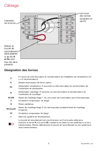
3 69-2815EFS—03 Câblage Désignation des bornes C Fil neutre du côté secondaire du transformateur de l’installation de climatisation (s’il y a 2 transformateurs). K Module économiseur de fils en option. Rc Alimentation climatisation. À raccorder au côté secondaire du transformateur de l’installation ...
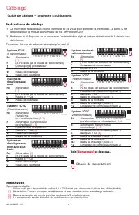
Page 16 - Guide de câblage – systèmes traditionnels; Boucle de raccordement; Instructions de câblage
69-2815EFS—03 4 Système 1C/1C (1 transformateur) Rc Alimentation [1] R [R+Rc reliés par la boucle de raccordement] Y Contacteur de compresseur C Neutre 24 V CA W Relais de chauffage G Relais de la soufflante Système de chauffage seule- ment Rc Alimentation [1] R [R+Rc reliés par la boucle de raccord...
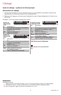
Page 17 - Guide de câblage – systèmes de thermopompes
5 69-2815EFS—03 Système de thermopompe 1C/1F Rc Alimentation [1] R [R+Rc reliés par la boucle de raccordement] Y Contacteur de compresseur C Neutre 24 V CA O/B Robinet de substitution [2] G Relais de la soufflante Système de thermopompe 2C/1F Rc Alimentation [1] R [R+Rc reliés par la boucle de racco...
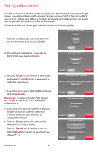
Page 18 - Configuration initiale
69-2815EFS—03 6 Configuration initiale Lors de la mise sous tension initiale, ou après une réinitialisation aux paramètres par défaut, les options initiales du thermostat (langue, emplacement et type de système) doivent être réglées pour définir le système de chauffage/refroidissement. Les autres op...
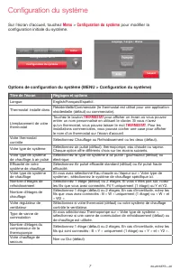
Page 19 - Configuration du système; Sur l’écran d’accueil, touchez; pour modifier la
7 69-2815EFS—03 Options de configuration du système (MENU > Configuration du système) Titre de l’écran Réglages et options Langue English/Français/Español. Thermostat installé dans Résidentielle/Commerciale (le thermostat est utilisé pour une application résidentielle (défaut) ou commerciale). L’...
Page 20 - Se connecter au réseau Wi-Fi; Rebalayer
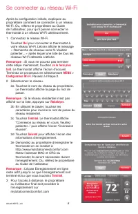
69-2815EFS—03 8 Se connecter au réseau Wi-Fi Après la configuration initiale, expliquez au propriétaire comment se connecter à un réseau Wi-Fi. Ou, référez le propriétaire au Guide de l’utilisateur, pour qu’il puisse connecter le thermostat à un réseau Wi-Fi ultérieurement.1 Connectez le réseau Wi-F...
Page 21 - Réglage des préférences avancées; Titre de l’écran
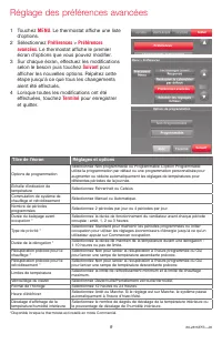
9 69-2815EFS—03 Réglage des préférences avancées 1 Touchez MENU . Le thermostat affiche une liste d’options. 2 Sélectionnez Préférences > Préférences avancées . Le thermostat affiche le premier écran d’options que vous pouvez modifier. 3 Sur chaque écran, effectuez les modifications selon le beso...
Page 22 - Dépannage
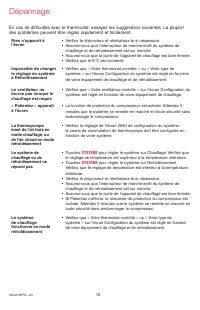
69-2815EFS—03 10 En cas de difficultés avec le thermostat, essayez les suggestions suivantes. La plupart des problèmes peuvent être réglés rapidement et facilement. Rien n’apparaît à l’écran • Vérifiez le disjoncteur et réinitialisez-le si nécessaire.• Assurez-vous que l’interrupteur de marche-arrêt...
Page 24 - AVIS RELATIF AU MERCURE :
® Marque de commerce déposée américaine.Apple, iPhone, iPad, iPod touch et iTunes sont des marques de commerce de Apple Inc. Toutes les autres marques de commerce sont propriété de leurs propriétaires respectifs.© 2014 Honeywell International Inc.69-2815EFS— 03 M.S. 02-14Imprimé aux États-Unis Systè...
Page 25 - Guía de instalación; Termostato con; pantalla; Condiciones interiores.
Guía de instalación ® Marca Registrada en los E.U.A. © 2014 Honeywell International Inc. Todos los derechos reservados. Termostato con conexión WiFi 9000 pantalla táctil a color HOGAR. Presione para visualizar la pantalla de inicio. VENTILADOR. Seleccione una modalidad para el ventilador. SISTEMA. S...
Page 26 - Instalación de la placa para pared; PRECAUCIÓN: RIESGO ELÉCTRICO; AVISO SOBRE EL MERCURIO
69-2815EFS—03 2 LEVEL HERE M34819 CK Rc R W- O/B YG W2- Aux/E Y2L M34500A Instalación de la placa para pared En tablarroca, realice agujeros de 3/16". En yeso, realice agujeros de 7/32". Anclas de expansión Placa para pared Agujero para el cable Tornillos de montaje PRECAUCIÓN: RIESGO ELÉCTR...
Page 27 - Cableado; Designaciones de terminales
3 69-2815EFS—03 Cableado Designaciones de terminales C Cable común del lado secundario del transformador del sistema de refrigeración (si hay 2 transformadores). K Módulo de cableado opcional. Rc Alimentación de energía de refrigeración. Conecte al lado secundario del transformador del sistema de re...
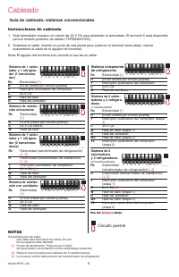
Page 28 - Guía de cableado: sistemas convencionales; NOTAS; Circuito puente
69-2815EFS—03 4 Sistema de 1 calen- tador y 1 refrigera- dor (1 transforma- dor) Rc Electricidad [1] R [R+Rc unidos por circuito puente] Y Interruptor automático del compresor C 24 V CA W Relé de calor G Relé del ventilador Sistema de calefac- ción únicamente Rc Electricidad [1] R [R+Rc unidos por c...
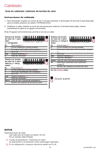
Page 29 - Guía de cableado: sistemas de bomba de calor; Instrucciones de cableado
5 69-2815EFS—03 Sistema de bomba de calor de 1 calen- tador y 1 refrigerador Rc Electricidad [1] R [R+Rc unidos por circuito puente] Y Interruptor automático del compresor C 24 V CA O/B Válvula inversora [2] G Relé del ventilador Sistema de bomba de calor de 2 calen- tadores y 1 refrig- erador Rc El...
Page 30 - Configuración inicial
69-2815EFS—03 6 Siguiente Siguiente Siguiente Siguiente Configuración inicial Luego de la puesta en marcha inicial o después de un reinicio a la programación predeterminada de fábrica, las opciones iniciales del termostato (idioma, ubicación y tipo de sistema) se deben configurar para definir el sis...
Page 31 - Configuración del sistema; En la pantalla de inicio, toque; Menú; para modificar la
7 69-2815EFS—03 Opciones de la configuración del sistema (MENÚ > Configuración del sistema ) Título de la pantalla Configuraciones y opciones Idioma English/Français/Español. Termostato instalado en Hogar/comercio (El termostato se utiliza en un ambiente residencial (predeterminado) o comercial)....
Page 32 - Conexión con la red de Wi-Fi; Lo haré después; Terminado
69-2815EFS—03 8 Conexión con la red de Wi-Fi Después de la configuración inicial, indique al propietario residencial los pasos necesarios para la conexión a una red de WiFi. O refiera al propietario residencial a la Guía del usuario para que él pueda conectar el termostato a una red WiFi en otro mom...
Page 33 - Configuración de preferencias avanzadas; Título de la pantalla
9 69-2815EFS—03 Configuración de preferencias avanzadas 1 Toque MENÚ . El termostato muestra una lista de opciones. 2 Seleccione Preferencias > Preferencias avanzadas . El termostato muestra la primera pantalla de opciones que puede modificar. 3 En cada pantalla, realice los cambios necesarios; l...
Page 34 - Localización y solución de problemas; SISTEMA
69-2815EFS—03 10 Localización y solución de problemas Si tiene dificultades con el termostato, intente seguir las sugerencias que se indican a continuación. La mayoría de los problemas pueden solucionarse de manera fácil y rápida. La pantalla está en blanco • Revise el interruptor de circuito y, si ...
Page 35 - Accesorios y piezas de repuesto; Póngase en contacto con su distribuidor para solicitar piezas de; Especificaciones
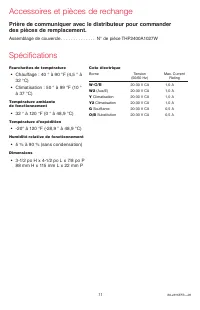
11 69-2815EFS—03 Accesorios y piezas de repuesto Póngase en contacto con su distribuidor para solicitar piezas de repuesto. Ensamblaje de la placa de cubierta ............. Pieza número THP2400A1027W Especificaciones Rangos de temperatura • Calor: 40 °F a 90 °F (4,5 °C a 32 °C). • Frío: 50 °F a 99 °...
Page 36 - Automatización y control desenlace; ¿Necesita asistencia?; Para obtener asistencia relacionada con este producto,; DESCONECTE LA ELECTRICIDAD ANTES DE LA INSTALACIÓN.; AVISO SOBRE EL MERCURIO:
® Marca Registrada en los E.U.A.Apple, iPhone, iPad, iPod touch y iTunes son marcas comerciales de Apple Inc. Todas las demás marcas comerciales son propiedad de sus respectivos dueños.© 2014 Honeywell International Inc.69-2815EFS— 03 M.S. 02-14Impreso en EE. UU. Automatización y control desenlace H...


 Honeywell TH8320U1016 Manual
 Honeywell TH8320WF Manual
 Honeywell TH8320ZW User Manual
 Honeywell TH8321 Manual
 Honeywell TH8321U Manual
 Honeywell Thermostat CM921 User Manual
 Honeywell Thermostat PRO 4000 User Manual
 Honeywell Thermostat RTH111 User Manual
 Honeywell Thermostat RTH230B User Manual
 Honeywell Thermostat RTH2510 User Manual
 Honeywell Thermostat RTH6500WF User Manual