Honeywell D - Manual

Honeywell D – Manual, read for free online in PDF format. We hope this helps you resolve any issues you may have. If you have further questions, please contact us through the contact form.


Table of Contents:
- Page 2 – T8112C,D ELECTRONIC PROGRAMMABLE THERMOSTATS; W Y G; Wiring Thermostat; CAUTION
- Page 3 – Fig. 7. Typical hookup in three wire cool
- Page 4 – Mounting Thermostat on Mounting Plate; Engage tabs at the top of thermostat and mounting
- Page 5 – SETTINGS; Fan Switch; FAN ON: The fan runs continuously. Used for improved; System Switch; COOL: The thermostat controls the air conditioning; Installing Batteries; IMPORTANT
- Page 6 – CHECKOUT; Heating
- Page 7 – TROUBLESHOOTING GUIDE; If...
X-XX UL
INSTALLATION INSTRUCTIONS
®U.S. Registered Trademark
Copyright © 1998 Honeywell Inc. • • All Rights Reserved
T8112C,D Electronic
Programmable Thermostats
APPLICATION
The T8112C,D thermostats provide electronic
programmable control for 24 to 30 Vac heating and
cooling systems.
RECYCLING NOTICE
If this control is replacing a control that contains
mercury in a sealed tube, do
not place your old
control in the trash.
Contact your local waste management authority
for instructions regarding recycling and the proper
disposal of the old thermostat.
INSTALLATION
When Installing this Product…
1. Read these instructions carefully. Failure to follow
them could cause a hazardous condition.
2. Check the ratings given in the instructions and on
the product to make sure the product is suitable for
your application.
3. Installer must be a trained experienced service
technician.
4. After installation is complete, check out product
operation as provided in these instructions.
CAUTION
1. Disconnect power supply to prevent electrical
shock or equipment damage.
2. After wiring is complete, push excess wire
back into the hole and plug hole with
nonhardening caulk, putty or insulation to
prevent drafts from affecting thermostat
operation.
Location
Install the thermostat about 5 ft. (1.5m) above the floor in
an area with good air circulation at average temperature.
Do not install the thermostat where it can be affected by:
— drafts, or dead spots behind doors and in corners.
— hot or cold air from ducts.
— radiant heat from sun or appliances.
— concealed pipes and chimneys.
— unheated (uncooled) areas such as an outside wall
behind the thermostat.
Mounting Plate Installation
Position mounting plate on the wall. Use a level to make
sure mounting plate is level. Use a pencil to mark the two
mounting holes. See Fig. 1.
WALL
WIRES THROUGH
WALL OPENING
WALL ANCHORS (2)
MOUNTING
PLATE
MOUNTING
SCREWS (2)
M1718
69-0917-2
Fig. 1. Mounting plate installation.
"Loading the manual" means you need to wait until the file loads and becomes available for online reading. Some manuals are very large, and the time they take to appear depends on your internet speed.
Was this manual helpful?
About this manual
- Brand
- Honeywell
- Model
- D
- Document type
- Manual
- Language(s)
- English
- Pages
- 8
- File size
- 97.9 KB
- Format
Summary
69-0917—2 2 T8112C,D ELECTRONIC PROGRAMMABLE THERMOSTATS 1. Remove mounting plate from the wall, and drill 3/16 inch holes in wall (if drywall) as marked. Forfirmer material such as plaster or wood, drill7/32 inch holes. Gently tap anchors (provided) intodrilled holes until flush with the wall. 2. R...
69-0917—2 3 T8112C,D ELECTRONIC PROGRAMMABLE THERMOSTATS R Rc W Y G B D A C 2-WIRE HEAT-ONLY (JUMPER INTACT) M1709B L1(HOT) L2 POWER SUPPLY. PROVIDE DISCONNECT MEANS ANDOVERLOAD PROTECTION AS REQUIRED. 1 1 HEATINGRELAY ORVALVE COIL JUMPER R Rc W Y G B D A C 5-WIRE HEAT/COOL (JUMPER REMOVED) L1(HOT) ...
69-0917—2 4 T8112C,D ELECTRONIC PROGRAMMABLE THERMOSTATS M1712A JUMPER (FACTORY-INSTALLED) REMOVE IF 5-WIRE SYSTEM INSERTSTRAIGHT UNDER SCREW HEAD 5/16 in. (8 mm)STRIP END OF WIRE VISIBLE HERE R Rc W Y G M3002A T8112C M5780 B. PRESS LOWER EDGE OF CASE TO LATCH. A. ENGAGE TABS AT TOP OF THERMOSTAT AN...
Ask a question
Related manuals
Popular Honeywell Other
More Honeywell Other models
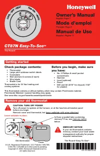 Honeywell CT87N1001 User Manual
 Honeywell CT3200 Manual
 Honeywell CT3455 Manual
 Honeywell CT3600 Manual
 Honeywell CT3611 Manual
 Honeywell D770 User Manual
 Honeywell D780 User Manual
 Honeywell D7900 Manual
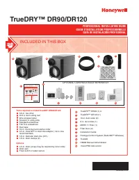 Honeywell Dehumidifier DR90 User Manual
 Honeywell DH-835 Manual
 Honeywell DH50W User Manual
 Honeywell DH90 Manual