Harbor Breeze 41180 - User Manual
Harbor Breeze 41180 Remote Control – User Manual, read for free online in PDF format. We hope this helps you resolve any issues you may have. If you have further questions, please contact us through the contact form.

H
arb or Bree z
e
H
a rb or Br eez
e
Black (to motor)
Note:
White (neutral) supply wires will not
be connected to the wall control.
Black/
White
Black
Black (live)
Blue
Green/
Yellow
(ground)
Green/Bare
Blue (to light)
ASSEMBLY INSTRUCTIONS
SAFETY INFORMATION
1. Use existing pull chains on the
desired fan to set fan speed to high
and to turn the light on.
2. Turn off circuit breakers and wall
switch to the fan.
DANGER:
Failure to
disconnect power supply prior to
installation may result in serious
injury or death.
• Connect Green Wire with Yellow Stripe from wall control
(A) to Bare/Green (ground) supply wire.
• Connect the Black wire from the wall control (A) to the
Black (live) supply wire.
• Connect the Black Wire with White Stripe from the wall
control (A) to the Black wire (fan power) from the outlet box.
• Connect the Blue Wire from the wall control (A) to the Blue
wire (light power) from the outlet box.
5. Wrap electrical tape (not
included) around each wire
connector (C) down to the wire.
Then, push wire connections
into the outlet box. Place
the Green and White wire
connections on the opposite
side of the outlet box from
the Black and Blue wire
connections.
6. Attach the wall control (A) to the
outlet box using the mounting
screws (D).
7. Attach the face plate (B) to
the wall control using the plate
screws (E).
8. Turn on power supply to the wall
control (A).
UNIVERSAL CEILING FAN
WALL CONTROL
ITEM #0745362
MODEL #41180
EB15500
9127 • 102715
Printed in
China
3
4
2
5
6
7
8
1
4.
Secure
all wiring
connections
with wire
connectors (C)
according to
diagram and
these steps:
Fan Pull
Chain
Light Pull
Chain
Outlet Box
Face
Plate
Switch
Outlet
Box
Wire
Connector
Qty. 4
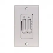
Face Plate
Qty. 1
Wall Control
Qty. 1
Plate
Screw
Qty. 2
Mounting
Screw
Qty. 2
Serial Number
Purchase Date
ATTACH YOUR RECEIPT HERE
Harbor Breeze
®
is a registered trademark of LF, LLC.
All rights reserved.
Questions?
Call our customer service department
at 1-800-643-0067, 8 a.m. - 6 p.m., EST, Monday -
Thursday, 8 a.m. - 5 p.m., EST, Friday.
A
B
C
D
E
Read instructions completely before installing wall control.
WARNING:
If the color of the household supply wires is different than what is referred to in the instructions below, a
professional electrician should determine proper wiring.
CAUTION:
•
Do not install in damp locations. For indoor use only.
•
Do not use with fans that have integrated remote controls.
•
Be sure the outlet box is properly grounded or that a green or bare (ground) wire is present.
•
This unit is intended to control a ceiling fan with electrical source of AC 110/120V, 60Hz.
3. Identify and label wires from existing
fan and light switches. Then, remove
the existing face plate and switch
from the outlet box.
Note:
The white supply wires
(neutral) will remain in the outlet box
secured with a wire connector.
Important:
This wall control
requires separate wiring for the
ceiling fan and light kit. If your fan
and light kit are controlled by a
single switch, additional wiring will
be required.
C
A
C
D
A
E
B
"Loading the manual" means you need to wait until the file loads and becomes available for online reading. Some manuals are very large, and the time they take to appear depends on your internet speed.