Page 2 - anual; FOR QUALIFIED AND SPECIALLY TRAINED PERSONS; special means to avoid injuries to eyes and skins.
O m perator's anual WARNING! BEFORE USING THE WELDING MACHINE READ THE INSTRUCTIONMANUAL CAREFULLY! FOR QUALIFIED AND SPECIALLY TRAINED PERSONS ONLY AFTER PROPER READING OF THIS MANUAL IS ALLOWED TO USE AND TOMAINTAIN THIS WELDING MACHINE. The detailed description, safety rules and all required info...
Page 4 - Technical Specification; escription; diameter of the wire is between 0 6 1 0
2. Technical Specification The manufacturer reserves himself the right to make the manual's content or welder's functionchange without any preliminary notification of the users. 3. D escription MIG Series Inverter is designed to be used with the advanced IGBT (Insulated Gate Bipolar Tube)and rapid r...
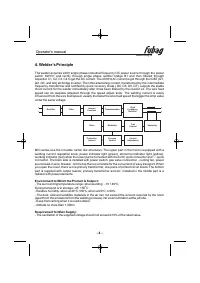
Page 5 - when at; Welder’s Principle
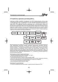
The welder acquires 220V single phase industrial frequency DC power source through the powerswitch SW101 and rectify through single phase rectifier bridge B1 and then filtered throughcapacitor C1, C2, C3, C4 to get the DC current. The 20 KHz AC current is got through the IGBT (Q1,Q2, Q3, and Q4) all...
Page 6 - The cable of torch must be replaced when it worn out.
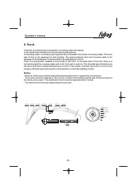
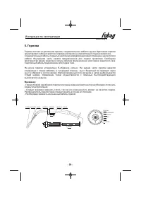
5. orch T The torch is composed by torch stand, connecting cable and handle.Torch stand is the interface of torch and wire feeding device.Connecting cable: covered by nylon pipe the liner is loaded in the center of coreless cable. The innerpart of liner is the passage for wire feeding. The space bet...
Page 7 - Welder’s Placement
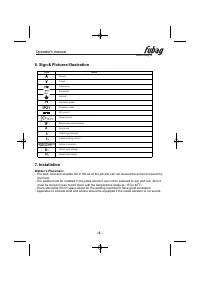
www.fubag.ru O m perator's anual - - 6 6. Sign & Pictures Illustration H 0 7. Installation Welder’s Placement - The dust, acid and erosible dirt in the air at the job site can not exceed the amount required by the norm. The welder must be installed in the place where it can not be exposed to sun...
Page 8 - Connection between Welder and Power Source; Wire end under the “Wire Reel”, opposite wire feeder.
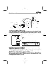
www.fubag.ru O m perator's anual - - 7 Connection between Welder and Power Source The installation and connection of MIG WeldingConnection and installation of the wire feeder Connect the power source cable at the back board of the welder into the single phase 220 voltagepower network with breaker; 3...
Page 9 - welder and work piece.; Connection between Welder and Torch
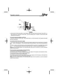
www.fubag.ru O m perator's anual - - 8 - Lead wire into “Wire Guide Pipe” of wire feeder, align wire with roll groove through “Drive Roll”, re- lead “Socket Tip” and press “Drive Roll”. (If more welding wire is needed, it will be done afterswitching on the power.) - Insert the connector of torch int...
Page 10 - Welding current adjustor
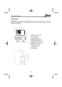
8. Operation ATTENTION: The protection class of MIG Series is IP21S. It is forbidden to put in a finger or insert a round bar less than 12.5 mm (metal bar in particular) into the welder. No heavy force can beemployed on the welder. IN www.fubag.ru O m perator's anual - - 9 1. ... ... . . ... Welding...
Page 11 - Work Piece cleaning Before Welding
Attention: - The ‘protection indicator light’ will be on after a long time operation, it shows that the innertemperature is over the permitted data, then the machine should be stopped using for some time tolet it cool down. It can continue using after the ‘protection indicator light’ is off. The pow...
Page 12 - a) Debugging before welding
Aluminium welding steps Sticking welding steps a) Debugging before welding Change the liner in MIG torch for telfon liner. Connect the torch, gas hose, grounding cable, argon gas tank, work piece and then turn on the power switch, the power indicator is on, at this time, the fan is working Turn on t...
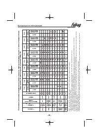
Page 13 - InMig 1
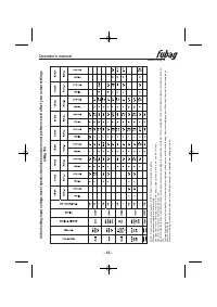
www.fubag.ru O m perator's anual - 2 - 1 Initial setting,input voltage,travel speed,cleanliness,and personal preference will affect your actual settings 6 InMig 1 0 DCEP - Direct current,electrode positive; DCEN - Direct current,electrode negative MIG gun replacement parts are T rafimet style Dual g...
Page 14 - relative humidity can not be more than 90%.
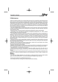
www.fubag.ru O m perator's anual - 3 - 1 9. Maintenance Unlike the traditional welder, the reversible welder belongs to the scientifically sophisticated productwhich uses the modern electronic component parts combined with high technology. Therefore thetrained personnels are required for its mainten...
Page 16 - List of Spare Parts
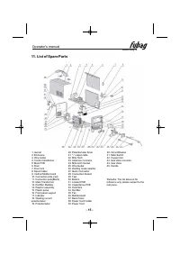
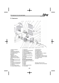
www.fubag.ru O m perator's anual - 5 - 1 11. List of Spare Parts 1. Gemel2. Enclosure3. Wire holder4. Control transformer5. Main PCB6. Door7. Door lock8. Spool holder9. Vertical Middle board10. Connection pole (red)11. Connection pole(Black)12. Main Transformer13. Rectifier Radiator14. Reactor assem...
Page 18 - Complete Set Specification
www.fubag.ru O m perator's anual - 7 - 1 13. Complete Set Specification 14. Transport & Storage 15. Warranty Inverter MIG Welder............................................1Product Certificate..............................................1Operator’s Manual...........................................
Page 19 - Инструкция по эксплуатации; ПЕРЕД ИСПОЛЬЗОВАНИЕМ СВАРОЧНОГО АППАРАТА; Правила безопасности; используйте очки с защитным затемненным стеклом.
www.fubag.ru Инструкция по эксплуатации ВНИМАНИЕ! ПЕРЕД ИСПОЛЬЗОВАНИЕМ СВАРОЧНОГО АППАРАТА ВНИМАТЕЛЬНО ОЗНАКОМЬТЕСЬ С ДАННОЙ ИНСТРУКЦИЕЙ. К использованию и обслуживанию сварочного аппарата допускается толькоквалифицированный и специально обученный персонал, ознакомленный с даннойинструкцией. Вэтой и...
Page 20 - Перед началом работы следует тщательно проверить:
- Проверьте подключение входных и выходных кабелей, заземление и т.д.- Техническое обслуживание должны выполнять только квалифицированные специалисты. - Если ваш сварочный аппарат был только что установлен или к работе приступает новый оператор, следует проверить сопротивление изоляции между обмотка...
Page 21 - Технические характеристики
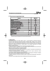
2. Технические характеристики Производитель имеет право вносить изменения как в содержание данной инструкции, так и в конструкцию сварочного аппарата без предварительного уведомления пользователей. 3. Описание Инверторный аппарат для MIG сварки создан с использованием усовершенствованнойтехнологии I...
Page 24 - Расшифровка пиктограмм; Размещение сварочного аппарата; должно быть 50 см
www.fubag.ru Инструкция по эксплуатации - 3 - 2 6. Расшифровка пиктограмм H 0 7. Установка Размещение сварочного аппарата - Количество пыли, кислоты и грязи в воздухе в рабочей зоне не должно превышать значение, указанное в нормативах (за исключением выбросов от сварочного аппарата) - Сварочный аппа...
Page 25 - Подсоединение источника питания; Конец проволоки должен
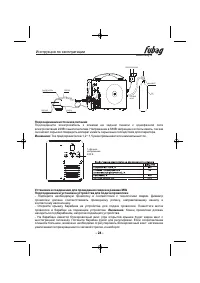
www.fubag.ru Инструкция по эксплуатации - 4 - 2 Подсоединение источника питания Установки и соединения для проведения сварки в режиме MIG Подсоединение и установка устройства для подачи проволоки Подсоедините электрок абель к клемам на задней панели к однофазной сетиэлектропитания 220Вс выключателем...
Page 26 - Подсоединение горелки
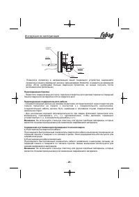
www.fubag.ru Инструкция по эксплуатации - 5 - 2 - Поместите проволоку в направляющий канал подающего устройства, выровняйте проволоку в канале приводного ролика, перенаправьте Socket tip и нажмите на приводнойролик. (Если необходимо больше сварочной проволоки, ее можно получить послевключения электр...
Page 28 - а) Регулировка перед проведением сварки; Зачистка свариваемого материала перед выполнением сварки
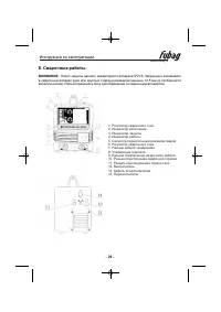
Внимание: - Индикатор защиты загорится после долгого периода работы, что означает, что внутренняятемпература превышает допустимое значение, в таком случае следует остановить аппаратна некоторое время и дать ему остыть. Работу можно продолжить после того, как индикаторзащиты погаснет.- После завершен...
Page 31 - Техническое обслуживание
www.fubag.ru Инструкция по эксплуатации - 0 - 3 9. Техническое обслуживание Вотличие от стандартного сварочного аппарата, данный сварочный аппарат являетсяусовершенствованным, в котором используются современные электронные компоненты исовершенная технология. Поэтому проведение технического обслужива...
Page 32 - Неисправности и их устранение
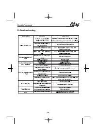
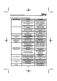
www.fubag.ru Инструкция по эксплуатации - 1 - 3 10. Неисправности и их устранение
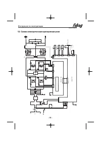
Page 34 - Схема электрическая принципиальная
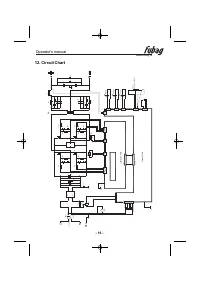
www.fubag.ru Инструкция по эксплуатации - 3 - 3 12. Схема электрическая принципиальная M MA- 18 0- P W R 2 1 2 1 4321 4321 CN 1 CN 20 2 F FA N 1 CT 1 21 H and y M IG -S CN 201 21 21 YEL L OW LED20 3 GR EEN LE D 201 CN1 01 5 4 3 2 1 220: 23+ 23 |19/ 15V A T1 0 1 A C 220V 50 /60H z PE N L 1 6 A /25 0V...
Page 35 - Хранение и транспортировка
www.fubag.ru Инструкция по эксплуатации - 4 - 3 13. Комплектация 14. Хранение и транспортировка 5. Гарантийные обязательства 1 Инверторный аппарат............................................1 штСертификат............................................................1 штРуководство по эксплуатации........