Page 3 - PRODUCT LABEL; codes and specifications:
3 3 Dear Customer, Thank you for having purchased and given your preference to our product. The safety precautions and recommendations reported below are for your own safety and that of others. They will also provide a means by which to make full use of the features offered by your appliance. Please...
Page 4 - IMPORTANT SAFETY PRECAUTIONS AND RECOMMENDATIONS; professionally qualified technician.; This film must be removed before using the; IMPORTANT: The use of suitable protective clothing/gloves is
4 4 IMPORTANT SAFETY PRECAUTIONS AND RECOMMENDATIONS IMPORTANT: This appliance is designed and manufactured solely for the cooking of domestic (household) food and is not suitable for any non domestic application and therefore should not be used in a commercial environment. The appliance guarantee w...
Page 5 - After use, ensure that the controls are in the off position.
5 5 • Do not attempt to modify the technical characteristics of the appliance as this may become dangerous to use. The manufacturer declines all responsibility for any inconvenience resulting from the inobservance of this condition. • Do not operate your appliance by means of an external timer or se...
Page 10 - INSTALLATION; personal injury of damage.; handling or installing this appliance.
10 10 INSTALLATION 1 IMPORTANT: • The appliance is designed and approved for domestic use only and should not be installed in a commercial, semi commercial or communal environment. Your product will not be guaranteed if installed in any of the above environments and could affect any third party or p...
Page 11 - STANDARD INSTALLATION; Description; for flush
11 11 FLUSH INSTALLATION (MODELS WITHOUT METAL TRIM/S ONLY) If you wish to install the hob flush with the work surface, it is neccessary to execute/carry out a miling in the hole of the cut-out as indicated in fig. 1.1b. STANDARD INSTALLATION Measures (mm) Description A (*) B (*) C (**) D D1 E E1 60...
Page 12 - FITTING REQUIREMENTS
12 12 FITTING REQUIREMENTS This cooktop can be built into a working surface from 20 mm thick and 600 mm deep. In order to install the ceramic hob into the kitchen fixture, a hole with the dimensions shown in figures 1.1a or 1.1b has to be made, keeping in consideration the following: • The cooktop s...
Page 13 - Oven with
13 13 min 5 mm min 30 mm min 25 mm min 5 mm min 30 mm min 25 mm Minimum clearances and ventilation requirements (oven installed below) Minimum clearances and ventilation requirements (cupboard or drawer space below) Oven with cooling fan 650 mm 500 mm 450 mm 50 mm minimum between the side of the cut...
Page 14 - FASTENING THE COOKTOP; metal clips are mounted correctly as shown in the figure 1.5.; Adhesive side
14 14 FASTENING THE COOKTOP Each cooktop is provided with an installation kit including brackets and screws for fastening the cooktop to benches from 20 mm thick. Before you install the cooktop, make sure that the work surface is square and level, and no structural members interfere with space requi...
Page 15 - ELECTRICAL SECTION; ELECTRICAL REQUIREMENTS; and following the appropriate safety regulations.; multiple power points as these may overheat and catch fire.; VOLTAGE AND POWER CONSUMPTION
15 15 ELECTRICAL SECTION 2 IMPORTANT: Installation must be carried out according to the manufacturer’s instructions. Incorrect installation may cause harm and damage to people, animals or property, for which the manufacturer accepts no responsibility.Before carrying out any work on the electrical se...
Page 16 - MODELS SUPPLIED WITH POWER CORD ALREADY FITTED TO THE APPLIANCE; FEEDER CABLE SECTION TYPE:; agent or a similarly qualified person in order to avoid a hazard.; Connection with wall box connection.
16 16 MODELS SUPPLIED WITH POWER CORD ALREADY FITTED TO THE APPLIANCE FEEDER CABLE SECTION TYPE: • H05RR-F, H07RN-F; • or H05VV-F, H05V2V2-F (resistant to temperatures of 90°C) 220-240 V ac 3 x 6 mm 2 (*) or 5 x 2,5 mm 2 (*) (**) 380-415 V 2N ac 5 x 2,5 mm 2 (*) (**) 380-415 V 3N ac 5 x 2,5 mm 2 (*)...
Page 17 - CONNECTION OF THE POWER SUPPLY CABLE; Unscrew the screw “; A B
17 17 CONNECTION OF THE POWER SUPPLY CABLE Important! This cooktop must be connected to the electricity supply only by an authorised person. To connect the feeder cable to the hob it is necessary to carry out the following operations: • Unscrew the screw “ A ” • Unhook the terminal board cover by in...
Page 18 - MODELS SUPPLIED WITH POWER CORD 5x2,5 mm
18 18 • The cooktop is supplied with a power cord already fitted to the appliance and it is suitable for a single-phase type electrical connection. (fig. 2.4). • For the two-phase type electrical connection (fig. 2.5): – separate the black and brown wires by removing the metallic terminal; – remove ...
Page 19 - Grey
19 19 “220-240 V ac” connection “380-415 V 2N ac” connection “380-415 V 3N ac” connection Green - Yellow Green - Yellow Green - Yellow N Blue and Grey N Blue and Grey N Blue L Black and Brown L1 Black L1 Black / L2 Brown L2 Brown / / L3 Grey L N L1 N L2 220...240 V ac 220...240 V ac 220-240 V ac 380...
Page 20 - ELECTRIC DIAGRAM; Main power board; User interface; TB; Terminal block; UI
20 20 ELECTRIC DIAGRAM ELECTRIC DIAGRAM KEYMPB Main power board PS/FI Power supply/Filter UI User interface ID_145 Induction zone Ø145mm ID_160 Induction zone Ø160mm ID_OC Induction ‘Octa’ zone 160x180mm TB Terminal block ID_OC ID_OC UI ID_145 ID_160 TB MPB PS/FI
Page 21 - User guide
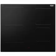
Page 22 - FEATURES AND TECHNICAL DATA; “Bridge” function: when enabled, the
22 22 FEATURES AND TECHNICAL DATA 1 Fig. 1.1 1. Induction cooking zone 190 x 210 mm Normal Power: 2100 W Booster Power: 2300 W Double Booster: 3000 W “Bridge” function: when enabled, the cooking zones work together as a single zone - 3700 W. 2. Induction cooking zone Ø 145 mm Normal Power: 1400 W Bo...
Page 23 - TOUCH CONTROLS; hob surface since they can get hot.
23 23 1 1 2 3 4 TOUCH CONTROLS 1. ON/OFF key 2. Setting selector 3. Pause function key 4. Child lock selection key 5. Chef cook function key 6. Warming function key 7. Automatic cooking (timer) display and keys 8. Selection zone key (one for each zone) 9. Timer key (one for each zone) Notes: • Each ...
Page 24 - USE OF INDUCTION HOB; INDUCTION COOKING SYSTEM; loss between the induction hob and the food.
24 24 The ceramic hob is fitted with induction cooking zones. These zones, shown by painted disks on the ceramic surface, are controlled by a touch control system.In the front central area of the hob, the displays of the touch control system indicate: USE OF INDUCTION HOB 2 = Cooking zone Off (not a...
Page 25 - zone switches Off automatically.; REMAINING HEAT INDICATORS; POWER IGNITION AND ADJUSTMENT OF A; COOKWARE/COFFEE POT FOR INDUCTION COOKING; To check if a pan/coffee pot is suitable or not:; Induction cooking zone; Cooking zones Bridged
25 25 If the pan detection symbol appears on the display, your pan is not suitable and your induction hob will not operate. After 10 minutes without detecting any pan, the cooking zone switches Off automatically. If the induction cooktop emits a humming noise when a zone is used on a high power leve...
Page 26 - Always use pans/coffee pots with thick, completely flat bottom.
26 26 IMPORTANT: Some cookware available on the market has an effective ferromagnetic area which is much smaller than the diameter of the pan itself. Avoid using this cookware because the induction cooktop may not function properly or may be damaged. Pay attention: The pan/coffee pot shall always be...
Page 27 - HOW TO SWITCH ON/OFF THE COOKTOP; Switching ON; Auto switch-Off: If a cooking zone is; Switching OFF; The cooktop may be switched Off at any time by pressing the key; POWER IGNITION AND ADJUSTMENT OF A COOKING ZONE; The power level can be modified at any time.; Increase
27 27 HOW TO SWITCH ON/OFF THE COOKTOP Switching ON Touch the key until the touch control system is lit (fig. 2.1). The displays of the cooking zones read “ 0 . ” or “ . ” (depending if a pan is placed or not on the relative zone). Notes: • If the safety Child Lock Safety or Key Lock Safety is activ...
Page 28 - “FAST HEATING” FUNCTION; To activate the “Fast Heating” function:; Power level of
28 28 GENTLEHEAT LOW SETTING (WARMING/MELTING) This function is ideal for the most delicate cooking tasks (such as melting chocolate), as the cooking zone will provide a very low continuous gentle heat. It is also ideal for keeping cooked food warm and the gentle warming of delicate foods.To turn On...
Page 29 - “FULL BRIDGE” FUNCTION (EXTENDABLE MAXI ZONE); Select the power level [from “; Note: It is not possible to activate the Double Booster function.
29 29 “FULL BRIDGE” FUNCTION (EXTENDABLE MAXI ZONE) This function can be used to link the two zones (only for induction cooking zone 160 x 180 mm) in “Bridge” mode, to create an extended maxi zone which is ideal for large rectangular pans or specialist fish cookware.To enable this function: • Switch...
Page 30 - BOOSTER FUNCTION; To activate the “Booster” function:
30 30 BOOSTER FUNCTION This function allows the cooking zone to operate at the “Booster” maximum power (above the nominal power) for maximum 5 minutes; it could be used, for example, to rapidly heat up large amount of water. To activate the “Booster” function: • T he touch control must be switched O...
Page 31 - available because the hob is set at a too low maximum power level).; To activate the “Chef Cook” function press the key; DOUBLE BOOSTER FUNCTION; To activate the “Double Booster” function:; “Bridge” function is operating.
31 31 “CHEF COOK” FUNCTION (if this function is not displayed, it means that it is not available because the hob is set at a too low maximum power level). This function allows the zone to be ready to use at preset power levels for a maximum of 2 hours. This means that, once selecting the “Chef Cook”...
Page 33 - switched Off after a maximum preset; POWER LEVEL OF
33 33 OPERATION TIME LIMIT OF THE COOKING ZONES Each cooking zone is automatically switched Off after a maximum preset time if no operation is performed. The maximum preset time limit depends on the set power level, as illustrated in this schedule. Each operation on the cooking hob by using the touc...
Page 37 - Controlled by
37 37 MAXIMUM USABLE POWER FOR THE COOKING ZONES The cooking zones are controlled by 2 separate power boards: The maximum total power per each power board is 3700 W. Should the cooking zones of one power board require more than 3700 W, the last selected power level has priority and the power of the ...
Page 38 - USER MENU; To access the User Menu:
38 38 USER MENU With the user menu it is possible to customize some features as described in table 9.1. To access the User Menu: • Switch On the cooktop by touching the key . • Touch the key again and keep it pressed until the symbol starts blinking. • Touch the key and keeping it pressed touch, one...
Page 40 - MAXIMUM POWER MANAGEMENT; carry out any modification.; POWER MANAGEMENT WHEN USING THE COOKTOP; automatically displaying the new power level.
40 40 MAXIMUM POWER MANAGEMENT Depending on the specific market requirements, the product is supplied with a maximum power (factory setting) as indicated on the rating label (see possible options in table below). The maximum power can be modified in any time (100W steps) by accessing the User Menu, ...
Page 41 - Erxx; Switch Off the cooktop and disconnect it from the mains.; ERROR CODES ON THE DISPLAYS OF THE COOKING ZONES
41 41 Error code What to do Erxx or display not operative 1. Switch Off the cooktop and disconnect it from the mains. 2. Wait for about 1 minute, then reconnect the cooktop and turn on the cooking zones. 3. Wait for about 1 minute and if the error message does not appear again the cooking zones can ...
Page 42 - SAFETY HINTS; • Do not use the hob if the glass
42 42 SAFETY HINTS • Before switching on make sure that you have the correct cooking zone for the hotplate chosen. It is advisable to put the pan on the hotplate before switching on and to take it away after switching off. • Use correct cookware suitable for induction cooking (normally identified by...
Page 43 - CLEANING AND MAINTENANCE; GENERAL ADVICE; and disconnected from the electrical power supply.; It is advisable to clean when the appliance is cold.; handling or cleaning of this appliance.; which could cause irreparable surface damage.; and may contain sharp or rough edges, that may cause injury.
43 43 CLEANING AND MAINTENANCE 3 GENERAL ADVICE • Before you begin cleaning, you must ensure that the appliance is switched off and disconnected from the electrical power supply. • It is advisable to clean when the appliance is cold. • Avoid leaving alkaline or acidic substances (lemon juice, vinega...
Page 44 - CLEANING THE CERAMIC HOB
44 44 CLEANING THE CERAMIC HOB • Remove spillages and other types of incrustations. • Dust or food particles can be removed with a damp cloth. • If you use a detergent, please make sure that it is not abrasive or scouring. Abrasive or scouring powders can damage the glass surface of the hob. • All t...
Page 45 - SERVICE AND MAINTENANCE; Servicing the appliance:; Both the fuse and the mains fuse are intact.
45 45 SERVICE AND MAINTENANCE Servicing the appliance: Service may be obtained by contacting our Customer Service Centre to locate the nearest Authorised ELBA APPLIANCES Service Agent shared services with Fisher and Paykel Australia PTY LTD (ELBA Appliances AUS, a division of F&P AUS PTY LTD).: ...
Page 48 - w w w. d e l o n g h i c o o k i n g a p p l i a n c e s . c o m . a u
C o d . 11 0 6 3 3 6 - ß 2 D e s c r i p t i o n s a n d i l l u s t r a t i o n s i n t h i s b o o k l e t a r e g i v e n a s s i m p l y i n d i c a t i v e . T h e m a n u f a c t u r e r r e s e r v e s t h e r i g h t , c o n s i d e r i n g t h e c h a r a c t e r i s t i c s o f t h e m o d...