DeLonghi DEIND804 - User Manual
DeLonghi DEIND804 Hob – User Manual, read for free online in PDF format. We hope this helps you resolve any issues you may have. If you have further questions, please contact us through the contact form.
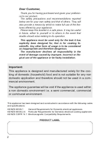
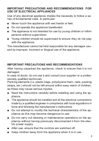
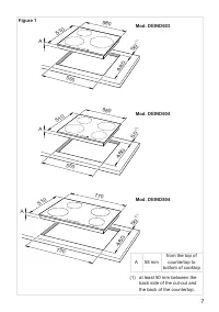
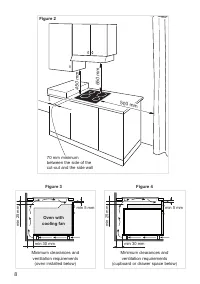
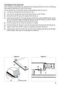
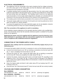
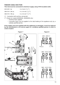
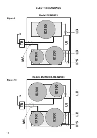
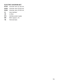
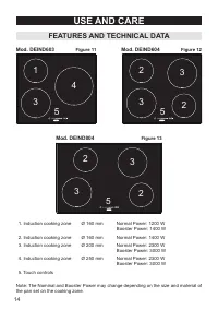
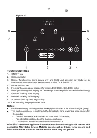
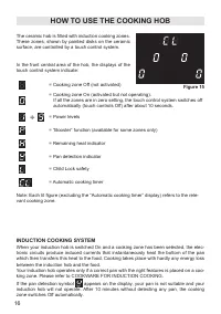
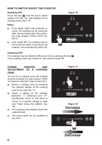
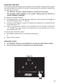
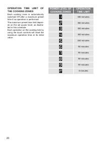
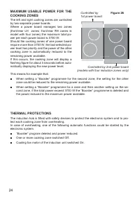
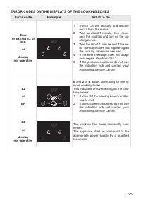
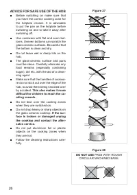
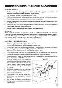


Table of Contents:
- Page 2 – PRODUCT LABEL; AS/NZS CISPR 14.1 Electromagnetic Compatibility Requirements.; This appliance is designed and manufactured solely for the coo-
- Page 3 – ries of fundamental rules. In particular:; IMPORTANT PRECAUTIONS AND RECOMMENDATIONS; sionally qualified technician.
- Page 4 – agent or a similarly qualified person in order to avoid a hazard.
- Page 5 – will not be affected by the electromagnetic field.
- Page 6 – INSTALLATION; FITTING REQUIREMENTS; in figure 1 has to be made, keeping in consideration the following:
- Page 7 – Figure 1
- Page 8 – Oven with
- Page 9 – FASTENING THE COOKTOP; Cut the unit according to the dimensions in fig. 1.; min; Figure 5
- Page 10 – ELECTRICAL REQUIREMENTS; withstand the load specified on the plate.; and in compliance with established electrical regulations.; CONNECTION OF THE POWER SUPPLY CABLE
- Page 11 – FEEDER CABLE SECTION; Notes for models DEIND604, DEIND804 only:; Figure 7
- Page 12 – ELECTRIC DIAGRAMS; Figure 9
- Page 13 – ELECTRIC DIAGRAM KEY; UI
- Page 14 – USE AND CARE; Induction cooking zone; FEATURES AND TECHNICAL DATA
- Page 15 – TOUCH CONTROLS; combination with other keys, see chapter CHILD LOCK SAFETY); lids should not be placed on the hob surface since they can get hot.
- Page 16 – The ceramic hob is fitted with induction cooking zones.; INDUCTION COOKING SYSTEM; king zone. Please refer to COOKWARE FOR INDUCTION COOKING.; HOW TO USE THE COOKING HOB
- Page 17 – Induction cooking zone
- Page 18 – HOW TO SWITCH ON/OFF THE COOKTOP; Switching ON; POWER IGNITION AND; increase; Increase
- Page 19 – BOOSTER FUNCTION; The “Booster” function is always limited to a maximum of 5 minutes.; To activate the “Booster” function:
- Page 20 – switched Off after a maximum preset; POWER LEVEL OF
- Page 22 – CL
- Page 24 – flashing figure for about 3 seconds before auto; THERMAL PROTECTIONS; One or more cooking zone switched Off.
- Page 25 – Switch Off the cooktop and discon; ERROR CODES ON THE DISPLAYS OF THE COOKING ZONES
- Page 26 – ADVICE FOR SAFE USE OF THE HOB; Use cookware with flat and even bot; This also makes it more; PANS WITH ROUGH
- Page 27 – GENERAL ADVICE; and disconnected from the electrical power supply.; It is advisable to clean when the appliance is cold.; handling or cleaning of this appliance.; CLEANING THE CERAMIC HOB; CLEANING AND MAINTENANCE
- Page 28 – SERVICE AND MAINTENANCE; Servicing the appliance:; Authorised Delonghi Service Agent:; Servicing shall be carried out only by authorized personnel.
D E ’ L O N G H I
C O O K I N G
I N S TA L L AT I O N a n d S E R V I C E I N S T R U C T I O N S
U S E a n d C A R E I N S T R U C T I O N S
D E I N D 6 0 3
D E I N D 6 0 4
D E I N D 8 0 4
I N D U C T I O N B U I L T- I N C O O K T O P S
distributed by
DeLonghi Australia Pty Ltd
DeLonghi New Zealand Ltd
"Loading the manual" means you need to wait until the file loads and becomes available for online reading. Some manuals are very large, and the time they take to appear depends on your internet speed.
Other Manuals for DeLonghi DEIND804
Summary
2 Dear Customer, Thank you for having purchased and given your preferen- ce to our product. The safety precautions and recommendations reported below are for your own safety and that of others. They will also provide a means by which to make full use of the fea- tures offered by your appliance. Plea...
3 IMPORTANT PRECAUTIONS AND RECOMMENDATIONS FOR USE OF ELECTRICAL APPLIANCES Use of any electrical appliance implies the necessity to follow a se- ries of fundamental rules. In particular: ■ Never touch the appliance with wet hands or feet. ■ Do not operate the appliance barefooted. ■ The appliance ...
4 ■ WARNING: Accessible parts will become hot when in use. To avoid burns and scalds, young children should be kept away. ■ Young children should be supervised to ensure that they do not play with the appliance. ■ Children, or persons with a disability which limits their ability to use the appliance...