Page 3 - Contents
Contents 1 About your Dell PowerEdge FX2/FX2s.............................................................. 6 Terms used in the document ................................................................................................................6 Sled slot numbering ................................
Page 4 - Installing and removing PowerEdge FX2/FX2s enclosure
4 Installing and removing PowerEdge FX2/FX2s enclosure components............................................................................................................ 35 Customer and field replaceable units—PowerEdge FX2/FX2s .......................................................... 35 Safet...
Page 6 - About your Dell PowerEdge FX2/FX2s; Terms used in the document
1 About your Dell PowerEdge FX2/FX2s The Dell PowerEdge FX2/FX2s is a 2U enclosure that can support up to four half-width compute sleds, up to eight quarter-width compute sleds, up to two full-width compute sleds, or a mix of compute sled types. The PowerEdge FX2s enclosure also supports half-width ...
Page 8 - Sled slot numbering
Sled slot numbering Figure 1. Sled slot numbering—four-bay chassis Figure 2. Sled slot numbering—eight-bay chassis Figure 3. Sled slot numbering—two-bay chassis Figure 4. Sled slot numbering — six-bay chassis 8
Page 9 - Front panel features and indicators—PowerEdge FX2/
Figure 5. Sled slot numbering—three-bay chassis Front panel features and indicators—PowerEdge FX2/ FX2s Figure 6. Front panel features and indicators—PowerEdge FX2/FX2s Item Indicator, Button, or Connector Icon Description 1 System identification button The identification buttons on the front and ba...
Page 10 - Diagnostic indicators
Item Indicator, Button, or Connector Icon Description 4 KVM select button Enables you to map the KVM to the sleds. 5 Sleds PowerEdge FX2/FX2s supports up to:• four half-width compute sleds, or• eight quarter-width compute sleds, or• two full-width compute sleds, or• four quarter-width compute sleds ...
Page 11 - Power button functions
Health indicator Electrical indicator Condition Corrective Action The indicator blinks amber if the system experiences an electrical error (for example, voltage out of range, or a failed power supply or voltage regulator). See the CMC Chassis Log or system messages for the specific issue. If it is d...
Page 12 - KVM features; Back panel features and indicators—PowerEdge FX2s and
Powering off the chassis and sleds For a graceful shutdown of all the sleds and the chassis, press and hold the chassis power button for 4 to 10 seconds and release it. NOTE: Depending on the status of the sleds, graceful shutdown may not be possible. You may opt for a forced shutdown by pressing an...
Page 14 - Power supply unit indicators
Item Indicator, Button, or Connector Description 8 I/O module (2) Provides Ethernet connectivity to the compute sleds in the enclosure. 9 I/O module ports Network interface for I/O modules. 10 I/O module indicators Two indicators for:• Status• Power Power supply unit indicators Each AC power supply ...
Page 15 - I/O module indicators
Convent ion Power indicator pattern Condition CAUTION: When correcting a PSU mismatch, replace only the PSU with the flashing indicator. Swapping the opposite PSU to make a matched pair can result in an error condition and unexpected system shutdown. To change from a High Output configuration to a L...
Page 16 - CMC module; CMC indicators
Indicator Description Status indicator Blue The I/O module is operating normally. Blinking Blue The CMC is identifying the I/O module. Blinking Amber The I/O module is in a fault condition. Off The I/O module is powered off, or booting is in progress. For more information, see the I/O module documen...
Page 17 - Daisy-chain CMC network connection
– Supports setting an optional enclosure Maximum Power Limit, which either alerts or takes actions, such as throttling compute sleds and/or preventing the power up of new compute sleds to keep the enclosure under the defined maximum power limit. – Monitors and automatically controls cooling fans bas...
Page 18 - Cooling fan indicator codes
Figure 12. CMC daisy-chaining 1. management network 2. CMC Cooling fan indicator codes Each cooling fan has an LED that indicates the power status of the cooling fan. Indicator Pattern Condition Not lit Cooling fan is functioning correctly. Flashing Amber Indicates a problem with the cooling fan. 18
Page 19 - Configuration wizard; System messages
Figure 13. Cooling fan indicators 1. status indicator Configuration wizard The CMC is pre-configured to use a static IP address. To use Dynamic Host Configuration Protocol (DHCP): 1. Access the Chassis Management Controller (CMC) 2. Click Network . 3. Click IPv4 or IPv6 . 4. Select DHCP Enable . For...
Page 20 - Documentation matrix
Documentation matrix The documentation matrix provides information about documents that you can refer to, for setting up and managing your system. To... Refer to... Install your system into a rack Rack documentation included with your rack solution Set up your system and know the technical specifica...
Page 21 - Quick Resource Locator
To... Refer to... Know the features of the storage controller cards, deploy the cards, and manage the storage subsystem Storage controller documentation at dell.com/ storagecontrollermanuals See the event and error messages generated by the system firmware and agents that monitor system components D...
Page 22 - Initial system configuration; Before you begin; Setting up your PowerEdge FX2/FX2s
2 Initial system configuration Before you begin CAUTION: The enclosure power supplies must be connected to a PDU or to an electrical outlet. The power supplies require a 100 V to 120 V or 200 V to 240 V power source. You can select only one AC power input, as the system does not operate at both rang...
Page 23 - Logging in to the CMC
• Connect to one of the compute sleds and boot to the Human Interface Infrastructure (HII) browser to retrieve the CMC IP address. 10. Connect to the CMC IP address through the Web browser by using the default logon credentials. NOTE: The default IP address of the CMC is 192.168.0.120. The default u...
Page 24 - LAN On Motherboard network; Supported I/O modules
3 PowerEdge FX2/FX2s mapping configurations This section provides the following information on the connectivity of the compute sleds to the I/O module(s), PCIe slots, and Chassis Management Controller (CMC) of the enclosure: • LAN On Motherboard network and compute sled to I/O module port mapping co...
Page 26 - I/O module port mapping—eight-bay chassis
Figure 17. I/O module port mapping—half-width compute sleds with quad port NDC/network output A half-width compute sled configured with quad-port NDC is mapped to two ports on each I/O module. A half-width compute sled with four compute nodes is configured with a quad-port network output, which is m...
Page 28 - I/O module port mapping—three-bay chassis
Table 5. I/O module port mapping in a six-bay chassis Compute sled IO Module A1 (Top) IO Module A2 (Bottom) 1a 1 1 1b 2 2 1c 3 3 1d 4 4 3 5, 6 (for half-width compute sled with quad-port NDC)5 (for half-width compute sled with dual- port NDC) 5, 6 (for half-width compute sled with quad-port NDC)5 (f...
Page 29 - I/O module and PCIe mezzanine card configuration
In the three-bay chassis, a full-width compute sled is mapped to four ports on each I/O module. A half-width compute sled with quad port NDC is mapped to two ports on each I/O module. NOTE: A half-width compute sled with dual-port NDC is mapped to a single port on each I/O module. NOTE: In the three...
Page 30 - Configuring network settings for the I/O module; PCIe expansion slot mapping; PCIe slot mapping from compute sleds
Manual at dell.com/poweredgemanuals . The PCIe mezzanine cards are mapped to the PCIe expansion slots on the enclosure. For more information, see PCIe expansion slot mapping . NOTE: Only PCIe mezzanine cards can be installed in the compute sleds. Non-PCIe mezzanine cards such as Ethernet, Fibre Chan...
Page 32 - PCIe slot mapping from compute sleds mapped to storage sleds
Figure 24. Compute sled to PCIe slot mapping—six-bay chassis Figure 25. Compute sled to PCIe slot mapping—two-bay chassis Figure 26. Compute sled to PCIe slot mapping—three-bay chassis PCIe slot mapping from compute sleds mapped to storage sleds In PowerEdge FX2s enclosure configurations that suppor...
Page 34 - Managing PCIe slots; Internal management network
Figure 29. PCIe slot mapping from compute sled mapped to storage sleds—three-bay chassis Figure 30. PCIe slot mapping from compute sleds mapped to storage sleds—six-bay chassis Managing PCIe slots You can view the status of PCIe slots in the system, both individually as well as all of them at a time...
Page 35 - Customer and field replaceable units—PowerEdge FX2/; Safety instructions
4 Installing and removing PowerEdge FX2/ FX2s enclosure components This section provides information on installing and removing the enclosure components. For information on removing and installing the sled components, see the relevant sled Owner’s Manual at dell.com/ poweredgemanuals . Customer and ...
Page 36 - Removing the system cover
CAUTION: Do not operate the system without the cover for a duration exceeding three minutes. CAUTION: Many repairs may only be done by a certified service technician. You should only perform troubleshooting and simple repairs as authorized in your product documentation, or as directed by the online ...
Page 37 - Installing the system cover
NOTE: To ensure proper operation and cooling, replace the system cover within three minutes of removal. 1. Ensure that you read the Safety instructions . 2. Follow the procedure listed in Before working inside your system . Steps1. Rotate the cover lock counterclockwise to the unlock position. 2. Pr...
Page 38 - Sleds; Removing a compute sled
Steps1. Place the bottom edge of the cover, opposite the cover lock, into the slots on the system. 2. Lower the cover onto the system. 3. Slide the system cover toward the back of the system until the system cover is flush with the system surface. 4. Turn the cover lock clockwise to the lock positio...
Page 39 - Installing a compute sled
Figure 32. Removing and installing a compute sled 1. enclosure 2. compute sled 3. compute sled handle 4. release button on sled handle Next steps Install the compute sled or sled blank. Related Links Installing a compute sled Installing a compute sled Prerequisites CAUTION: Many repairs may only be ...
Page 40 - Removing a storage sled
3. Align the compute sled with the bay in the enclosure. 4. Slide the sled into the enclosure until the sled connectors are firmly engaged with the midplane connectors.The sled handle rotates toward the enclosure as the sled slides into the enclosure. 5. Press the sled handle to closed position unti...
Page 42 - Installing a storage sled
Installing a storage sled Installing a storage sled Prerequisites CAUTION: Many repairs may only be done by a certified service technician. You should only perform troubleshooting and simple repairs as authorized in your product documentation, or as directed by the online or telephone service and su...
Page 43 - Inside the system
Figure 35. Installing a storage sled 1. dotted line on storage sled 2. sled lock (2) Next steps Turn on the compute sled(s) to which the storage sled is mapped. The storage sled turns on. Related Links Safety instructionsRemoving a storage sled Inside the system CAUTION: Many repairs may only be don...
Page 45 - Removing the CMC module
CMC module Your system supports a hot-swappable CMC module that provides multiple systems management functions. Removing the CMC module Prerequisites CAUTION: Many repairs may only be done by a certified service technician. You should only perform troubleshooting and simple repairs as authorized in ...
Page 46 - Installing the CMC module; CMC module SD card
Installing the CMC module Prerequisites CAUTION: Many repairs may only be done by a certified service technician. You should only perform troubleshooting and simple repairs as authorized in your product documentation, or as directed by the online or telephone service and support team. Damage due to ...
Page 47 - Removing an I/O module
Figure 38. Removing and installing a CMC module SD card 1. SD card 2. SD card connector Next steps Install the CMC module and reattach any cables that were disconnected.The SD card is activated automatically. Related Links Removing the CMC moduleInstalling the CMC module I/O module Your system suppo...
Page 48 - Installing an I/O module; PCIe module
Figure 39. Removing and installing an I/O module 1. I/O module 2. I/O module handle 3. release latch Next steps Install the I/O module. Related Links Installing an I/O module Installing an I/O module Prerequisites CAUTION: Many repairs may only be done by a certified service technician. You should o...
Page 49 - Removing a PCIe module
Removing a PCIe module Prerequisites CAUTION: Many repairs may only be done by a certified service technician. You should only perform troubleshooting and simple repairs as authorized in your product documentation, or as directed by the online or telephone service and support team. Damage due to ser...
Page 50 - Installing a PCIe module; Expansion cards; Expansion card types and form factor
Installing a PCIe module Prerequisites CAUTION: Many repairs may only be done by a certified service technician. You should only perform troubleshooting and simple repairs as authorized in your product documentation, or as directed by the online or telephone service and support team. Damage due to s...
Page 51 - Expansion card operational power status; PCIe module indicators
Expansion card operational power status The following table provides information on the operational power status of expansion cards when they are installed in a PCIe slot mapped to a compute sled. Chassis status Compute sled status Expansion card status Off Off Off Standby Off Off On Off Off On On O...
Page 52 - Removing an expansion card
Removing an expansion card Prerequisites CAUTION: Many repairs may only be done by a certified service technician. You should only perform troubleshooting and simple repairs as authorized in your product documentation, or as directed by the online or telephone service and support team. Damage due to...
Page 53 - Installing an expansion card; Power supply units
Next steps 1. Install the PCIe module. 2. Turn on the compute sled to which the expansion card is mapped. Related Links Removing a PCIe moduleInstalling a PCIe module Installing an expansion card Prerequisites CAUTION: Many repairs may only be done by a certified service technician. You should only ...
Page 54 - Removing a power supply unit
Removing a power supply unit Prerequisites CAUTION: Many repairs may only be done by a certified service technician. You should only perform troubleshooting and simple repairs as authorized in your product documentation, or as directed by the online or telephone service and support team. Damage due ...
Page 55 - Installing a power supply unit; Cooling fans; Removing a cooling fan
Installing a power supply unit Prerequisites CAUTION: Many repairs may only be done by a certified service technician. You should only perform troubleshooting and simple repairs as authorized in your product documentation, or as directed by the online or telephone service and support team. Damage du...
Page 57 - Installing a cooling fan; Removing the cooling-fan cage
3. cooling fan (8) Next steps Install the cooling fan. Related Links Installing a cooling fanRemoving the system cover Installing a cooling fan Prerequisites CAUTION: Many repairs may only be done by a certified service technician. You should only perform troubleshooting and simple repairs as author...
Page 59 - Installing the cooling-fan cage; PCIe switch board; Removing the PCIe switch board
Removing the system coverRemoving a cooling fan Installing the cooling-fan cage Prerequisites CAUTION: Many repairs may only be done by a certified service technician. You should only perform troubleshooting and simple repairs as authorized in your product documentation, or as directed by the online...
Page 61 - Installing the PCIe switch board; Fan interface board
Removing a cooling fanRemoving the cooling-fan cageRemoving a PCIe module Installing the PCIe switch board Prerequisites CAUTION: Many repairs may only be done by a certified service technician. You should only perform troubleshooting and simple repairs as authorized in your product documentation, o...
Page 62 - Removing the fan interface board
Removing the fan interface board Prerequisites CAUTION: Many repairs may only be done by a certified service technician. You should only perform troubleshooting and simple repairs as authorized in your product documentation, or as directed by the online or telephone service and support team. Damage ...
Page 63 - Installing the fan interface board
3. spring-loaded screw (2) Next steps Install the fan interface board. Related Links Installing the fan interface boardRemoving the system coverRemoving a cooling fanRemoving the cooling-fan cage Installing the fan interface board Prerequisites CAUTION: Many repairs may only be done by a certified s...
Page 64 - Interposer module
Interposer module The interposer module allows you to install quarter-width sleds in the PowerEdge FX2/FX2s enclosure that comes pre-installed with half-width or full-width sleds. Your system supports up to two interposer modules. Figure 48. Top view of the interposer module 1. midplane connector (2...
Page 65 - Removing the bottom interposer module
Removing the bottom interposer module Prerequisites CAUTION: Many repairs may only be done by a certified service technician. You should only perform troubleshooting and simple repairs as authorized in your product documentation, or as directed by the online or telephone service and support team. Da...
Page 68 - Installing the bottom interposer module
Removing a storage sledRemoving a power supply unitRemoving the CMC moduleRemoving an I/O moduleRemoving a PCIe moduleRemoving the system coverRemoving a cooling fanRemoving the cooling-fan cage Installing the bottom interposer module Prerequisites CAUTION: Many repairs may only be done by a certifi...
Page 69 - Removing the top interposer module
2. Follow the procedure listed in After working inside your system . Related Links Removing the bottom interposer moduleInstalling the cooling-fan cageInstalling a cooling fanInstalling the system coverInstalling a PCIe moduleInstalling an I/O moduleInstalling the CMC moduleInstalling a power supply...
Page 72 - Installing the top interposer module
Removing a compute sledRemoving a storage sledRemoving a power supply unitRemoving the CMC moduleRemoving an I/O moduleRemoving a PCIe moduleRemoving the system coverRemoving a cooling fanRemoving the cooling-fan cageRemoving the bottom interposer module Installing the top interposer module Prerequi...
Page 73 - Midplane assembly; Removing the midplane assembly
• CMC module• power supplies• sleds 2. Follow the procedure listed in After working inside your system . Related Links Removing the top interposer moduleInstalling the bottom interposer moduleInstalling the cooling-fan cageInstalling a cooling fanInstalling the system coverInstalling a PCIe moduleIn...
Page 75 - Installing the midplane assembly
7. power interposer board Next steps 1. Install the midplane assembly. Related Links Installing the midplane assemblyRemoving a compute sledRemoving a storage sledRemoving a power supply unitRemoving the CMC moduleRemoving an I/O moduleRemoving the system coverRemoving a cooling fanRemoving the cool...
Page 76 - Power interposer board; Removing the power interposer board
Next steps 1. Install the following: • interposer module(s)• fan interface board, if applicable• PCIe modules and PCIe switch board, if applicable• cooling-fan cage• cooling fans• system cover• I/O module(s)• CMC module• power supplies• sleds 2. Follow the procedure listed in After working inside yo...
Page 77 - Installing the power interposer board
Steps1. Remove the Mylar insulator. 2. Disconnect the power bus bar and the cable cover from the midplane assembly. 3. Disconnect the power bus bar and the cable cover from the power interposer board. 4. Remove the four screws that secure the power interposer board to the carrier. 5. Lift the power ...
Page 78 - Control panel; Removing the control panel
Steps1. Place the power interposer board in the carrier. 2. Install the four screws to secure the power interposer board to the carrier. 3. Reconnect the power bus bar and cable cover to the power interposer board. 4. Reconnect the power bus bar and cable cover to the midplane assembly. 5. Install t...
Page 80 - Installing the control panel; KVM panel; Removing the KVM panel
Next steps Install the control panel. Related Links Installing the control panel Installing the control panel Prerequisites CAUTION: Many repairs may only be done by a certified service technician. You should only perform troubleshooting and simple repairs as authorized in your product documentation...
Page 82 - Installing the KVM panel
Figure 63. Removing and installing the KVM panel 1. screw 2. KVM panel cable 3. connector 4. KVM panel 5. KVM panel cover Next steps Install the KVM panel. Related Links Installing the KVM panel Installing the KVM panel Prerequisites CAUTION: Many repairs may only be done by a certified service tech...
Page 84 - Troubleshooting your system; Safety first—for you and your system
5 Troubleshooting your system NOTE: This chapter provides troubleshooting information for the PowerEdge FX2 and FX2s enclosures only. For troubleshooting information on the sleds, see the sled documentation at dell.com/poweredgemanuals . Safety first—for you and your system CAUTION: Many repairs may...
Page 85 - Troubleshooting enclosure components; Troubleshooting a wet enclosure; Troubleshooting power supply units
If the tests fail, see Getting Help . Troubleshooting enclosure components The following procedures describe how to troubleshoot the enclosure components. Troubleshooting a wet enclosure Prerequisites CAUTION: Many repairs may only be done by a certified service technician. You should only perform t...
Page 86 - Troubleshooting cooling problems; Troubleshooting cooling fans
NOTE: After installing a PSU, allow several seconds for the system to recognize the PSU and determine whether it is working properly. 3. If the problem is not resolved, swap or replace the PSU with a known good PSU. 4. If none of the power supplies show a fault LED and the sleds do not power on, che...
Page 87 - Troubleshooting expansion cards; Troubleshooting I/O modules
Troubleshooting expansion cards Prerequisites CAUTION: Many repairs may only be done by a certified service technician. You should only perform troubleshooting and simple repairs as authorized in your product documentation, or as directed by the online or telephone service and support team. Damage d...
Page 89 - Technical specifications—PowerEdge
6 Technical specifications—PowerEdge FX2/FX2s Enclosure specifications Physical Height 8.68 cm (3.41 inch) Width 43.35 cm (17.06 inch) without rack ears48.19 cm (18.97 inch) with rack ears Depth 85.16 cm (33.52 inch) Weight (maximum) 53 kg (116.8 lb) Weight (empty) 21.5 kg (47.4 lb) Compute sleds Po...
Page 94 - Getting help; Contacting Dell; Locating your system Service Tag
7 Getting help Contacting Dell Dell provides several online and telephone-based support and service options. If you do not have an active Internet connection, you can find contact information on your purchase invoice, packing slip, bill, or Dell product catalog. Availability varies by country and pr...


 Dell PowerEdge C4130 User Manual
 Dell PowerEdge C6100 User Manual
 Dell PowerEdge C6145 User Manual
 Dell PowerEdge C6220 User Manual
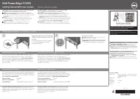 Dell Poweredge FC630 User Manual
 Dell PowerEdge M520 User Manual
 Dell PowerEdge M600 User Manual
 Dell PowerEdge M610 Quick Guide
 Dell PowerEdge M620 User Manual
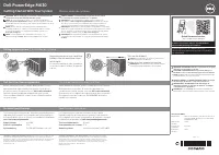 Dell PowerEdge M630 User Manual
 Dell PowerEdge M820 User Manual