Dell OPTIPLEX 9010 ALL-IN-ONE - User Manual

Dell OPTIPLEX 9010 ALL-IN-ONE – User Manual, read for free online in PDF format. We hope this helps you resolve any issues you may have. If you have further questions, please contact us through the contact form.


Table of Contents:
- Page 3 – Contents
- Page 7 – Working on Your Computer; Before Working Inside Your Computer
- Page 9 – Removing and Installing Components; Recommended Tools
- Page 13 – Installing the VESA Mount Bracket; Removing the Touchscreen Board
- Page 16 – Installing the Coin-Cell Battery; Removing the Optical Drive
- Page 19 – Installing the Hard Drive; Removing the Intrusion Switch
- Page 20 – Installing the Intrusion Switch
- Page 22 – Installing the Power-Supply Fan
- Page 25 – Removing the Input/Output Board Shield
- Page 30 – Removing the Speakers
- Page 32 – System Board Layout
- Page 33 – Installing the System Board
- Page 34 – Jumper Settings
- Page 35 – Removing the Display Panel
- Page 41 – Installing the Camera
- Page 43 – System Setup; Boot Sequence
- Page 44 – System Setup Options — BIOS Setup
- Page 52 – Updating the BIOS
- Page 53 – System and Setup Password
- Page 55 – Diagnostics; Power Supply Built in Self-Test
- Page 57 – Troubleshooting Your Computer; Diagnostic Power LED Codes
- Page 61 – Technical Specifications
- Page 67 – Contacting Dell
Dell OptiPlex 9010 All-In-One Touch
Owner's Manual
Regulatory Model: W04C
Regulatory Type: W04C001
"Loading the manual" means you need to wait until the file loads and becomes available for online reading. Some manuals are very large, and the time they take to appear depends on your internet speed.
Was this manual helpful?
About this manual
- Brand
- Dell
- Model
- OPTIPLEX 9010 ALL-IN-ONE
- Document type
- User Manual
- Language(s)
- English
- Pages
- 67
- File size
- 8.3 MB
- Format
Summary
Contents Notes, Cautions, and Warnings...................................................................................................2 1 Working on Your Computer.......................................................................................................7 Before Working Inside Your Com...
1 Working on Your Computer Before Working Inside Your Computer Use the following safety guidelines to help protect your computer from potential damage and to help to ensure your personal safety. Unless otherwise noted, each procedure included in this document assumes that the following conditions ex...
2 Removing and Installing Components This section provides detailed information on how to remove or install the components from your computer. Recommended Tools The procedures in this document may require the following tools: • Small flat-blade screwdriver • Phillips screwdriver • Small plastic scri...
Ask a question
Related manuals
Popular Dell Other
More Dell Other models
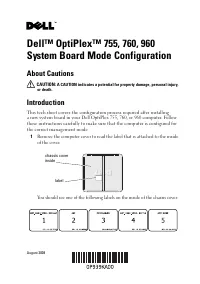 Dell OptiPlex 960 User Manual
 Dell OptiPlex 980 User Manual
 Dell OPTIPLEX 3010 Desktop User Manual
 Dell OptiPlex 3020M User Manual
 Dell OptiPlex 7010 User Manual
 Dell OptiPlex 9010 User Manual
 Dell OptiPlex 9020 User Manual
 Dell OptiPlex 9020 AIO User Manual
 Dell OptiPlex 9020M User Manual
 Dell OptiPlex 9030 User Manual
 Dell OptiPlex FX170 User Manual
- Dell OptiPlex G1 User Manual