Viking VGIC54828BSS - Manuals
Viking VGIC54828BSS Range – User Manual in PDF format online.
Manuals:
User Manual Viking VGIC54828BSS


Summary
3 Important - Read and Follow! Before beginning, please read these instructions completely and carefully. •DO NOT remove permanently affi xed labels, warnings, or plates from product. This may void the warranty. • All local and national codes and ordinances must be observed. Installation must confor...
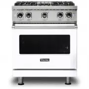
4 Dimensions 30” AND 36” W. RANGES 35-7/8” (91.1 cm) min. to 37” (94.0 cm) max. 1” (2.5 cm) 29-7/8” (75.9 cm) 35-7/8” (91.1 cm) 25-3/4” (65.4 cm) 45-1/8” (114.6 cm) 19-3/8” (49.2 cm) 8-1/8” (20.6 cm) 26-7/16” (67.2 cm) 1-5/8” (4.1 cm) 1” (2.5 cm) 35-7/8” (91.1 cm) min. to 37” (94.0 cm) max. 24-5/16”...
5 Specifi cations Description 30” W. (76 cm) Wide 36” W. (91 cm) Wide 48” W. (122 cm) Wide Overall width 29-7/8” (75.9 cm) 35-7/8” (91.1 cm) 47-7/8” (121.6 cm) Overall height from bottom To top of side panl Leg adjustment 35-7/8” (91.1 cm) min to 37” (94.0 cm) max 1-1/8” (2.9 cm) Overall depth from ...
Viking Ranges Manuals
-
 Viking EVGR530-4BAB
User Manual
Viking EVGR530-4BAB
User Manual
-
 Viking EVGR530-4BAG
User Manual
Viking EVGR530-4BAG
User Manual
-
 Viking EVGR530-4BBK
User Manual
Viking EVGR530-4BBK
User Manual
-
 Viking EVGR530-4BSS
User Manual
Viking EVGR530-4BSS
User Manual
-
 Viking EVGR530-4BWH
User Manual
Viking EVGR530-4BWH
User Manual
-
 Viking RVDR33025BSS
User Manual
Viking RVDR33025BSS
User Manual
-
Viking RVDR33025BSSLP
User Manual
-
 Viking RVER3301-5BSS
User Manual
Viking RVER3301-5BSS
User Manual
-
 Viking RVER3301-5BWH
User Manual
Viking RVER3301-5BWH
User Manual
-
 Viking RVGR33025BRE
User Manual
Viking RVGR33025BRE
User Manual
-
Viking RVGR33025BSS
User Manual
-
Viking RVGR33025BSSLP
User Manual
-
Viking RVGR33025BWH
User Manual
-
 Viking TVDR4814GDG
User Manual
Viking TVDR4814GDG
User Manual
-
Viking TVDR4816BBW
User Manual
-
Viking TVDR4816BKA
User Manual
-
Viking TVDR6618BSB
User Manual
-
 Viking VDR5304BSB
User Manual
Viking VDR5304BSB
User Manual
-
Viking VDR5304BSS
User Manual
-
Viking VDR5304BSSLP
User Manual