Triplett MG600 - Manuals
User Manual Triplett MG600


Summary
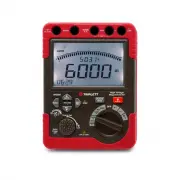
Introduction Congratulations on your purchase of the Triplett MG600 High Voltage Megohmeter/Insulation Tester. This meter provides four Insulation Resistance test ranges plus Continuity, AC/DC Voltage, Polarization Index and Dielectric Absorption Ratio measurements. Safety International Safety Symbo...
If the equipment is used in a manner not specified by the manufacturer, the protection provided by the equipment may be impaired. Do not use the Insulation resistance tester near explosive gas, vapor or dust. When using the test leads, keep fingers away from the lead contacts. Keep fingers behind th...
14. Function Indicator Insulation Resistance Testing CAUTIONS: Ensure that no electrical charge exists on the circuit under test. Insulated gloves should be worn while testing. Use extreme caution to avoid touching the tips of the test leads or the circuit under test when the PRESS TO TEST button is...
Triplett Multimeters Manuals
-
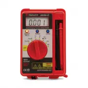 Triplett 2030
User Manual
Triplett 2030
User Manual
-
 Triplett 9055
User Manual
Triplett 9055
User Manual
-
 Triplett 9325
User Manual
Triplett 9325
User Manual
-
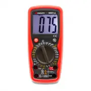 Triplett 9007A
User Manual
Triplett 9007A
User Manual
-
 Triplett 9007A-NIST
User Manual
Triplett 9007A-NIST
User Manual
-
 Triplett BBT858L
User Manual
Triplett BBT858L
User Manual
-
 Triplett CM1000
User Manual
Triplett CM1000
User Manual
-
 Triplett CM1000-NIST
User Manual
Triplett CM1000-NIST
User Manual
-
 Triplett CM1050
User Manual
Triplett CM1050
User Manual
-
 Triplett CM1050-NIST
User Manual
Triplett CM1050-NIST
User Manual
-
 Triplett CM1070
User Manual
Triplett CM1070
User Manual
-
 Triplett CM200
User Manual
Triplett CM200
User Manual
-
 Triplett CM200-NIST
User Manual
Triplett CM200-NIST
User Manual
-
 Triplett CM24
User Manual
Triplett CM24
User Manual
-
 Triplett CM400
User Manual
Triplett CM400
User Manual
-
 Triplett CM400-NIST
User Manual
Triplett CM400-NIST
User Manual
-
 Triplett CM450
User Manual
Triplett CM450
User Manual
-
 Triplett CM450-NIST
User Manual
Triplett CM450-NIST
User Manual
-
 Triplett CM600
User Manual
Triplett CM600
User Manual
-
Triplett CM600-NIST
User Manual