Page 3 - Preface; SAFETY PRECAUTIONS
Satellite P100 Maintenance Manual (960-Q02) 3 Preface This maintenance manual describes how to perform hardware service maintenance for the Toshiba Personal Computer Satellite P100 Series. The procedures described in this manual are intended to help service technicians isolate faulty Field Replaceab...
Page 5 - Conventions; Acronyms; Ctrl; and at the same time press
Satellite P100 Maintenance Manual (960-Q02) 5 Conventions This manual uses the following formats to describe, identify, and highlight terms and operating procedures. Acronyms On the first appearance and whenever necessary for clarification acronyms are enclosed in parentheses following their definit...
Page 6 - Table of Contents; Chapter 1; Procedure 1
6 Satellite P100 Maintenance Manual (960-Q02) Table of Contents Chapter 1 Hardware Overview 1.1 Features ..........................................................................................................................1 1.2 System Block Diagram .................................................
Page 8 - VGA
8 Satellite P100 Maintenance Manual (960-Q02) 2.9 Display Troubleshooting..............................................................................................35 Procedure 1 External Monitor Check...........................................................35 Procedure 2 Diagnostic Test Progra...
Page 9 - Chapter 3 Test Program for Field; Check DMI Information................................................ 3-55; Common
Satellite P100 Maintenance Manual (960-Q02) 9 Chapter 3 Test Program for Field 3.1 Tests and Diagnostics Software Overview ................................................................. 3-3 3.2 Executing the Diagnostic Test ............................................................................
Page 10 - Chapter 4
10 Satellite P100 Maintenance Manual (960-Q02) 3.21.1 How to operate a window …………………………………………3-62 3.21.2 How to Stop the Test Program ……………………………………. 3-62 3.21.3 Test Status Screen …………………………………………………3-62 3.21.4 Test Stop Display……………………………………………………3-64 3.21.5 How to enter data ……………………………………………………...
Page 12 - Appendices; Appendix E
12 Satellite P100 Maintenance Manual (960-Q02) Appendices Appendix A Handling the LCD Module ........................................................................... A-1 Appendix B Board Layout .................................................................................................B-1 Ap...
Page 16 - Satellite P100 Maintenance Manual(960-Q02) 1-1; Inverter
Hardware Overview Chapter 1 Satellite P100 Maintenance Manual(960-Q02) 1-1 Chapter 1 Contents 1.1 Features ..........................................................................................................................1 1.2 System Block Diagram ...............................................
Page 18 - Chapter 1 Hardware Overview; Satellite P100 Maintenance Manual (960-Q02) 1
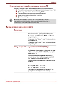
Chapter 1 Hardware Overview Satellite P100 Maintenance Manual (960-Q02) 1 Features 1.1 Features The Satellite P100 (Intel Platform) series are 2 spindle PCs running Intel® Celeron® M Processor 410 or higher. Intel® Core™ Solo Processor T1300 or higher. Intel® Core™ Duo Processor T2300 or higher. The...
Page 20 - Satellite P100 Maintenance Manual (960-Q02) 3
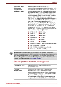
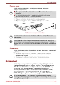
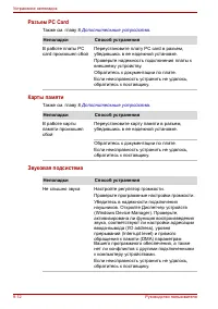
Chapter 1 Hardware Overview Satellite P100 Maintenance Manual (960-Q02) 3 θ PC card slot The PC card slot (PCMCIA) accommodates one 5mm Type II card. The slot support 16-bit PC cards and Card Bus PC cards. Card Bus supports 32-bit PC cards. θ Optical devices A DVD-ROM & CD-R/RW drive or DVD Supe...
Page 21 - Express Card
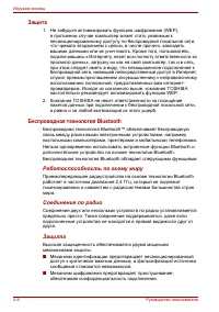
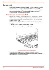
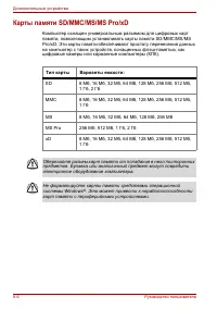
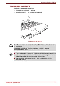
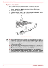
Chapter 1 Hardware Overview 4 Satellite P100 Maintenance Manual(960-Q02) θ Express Card ExpressCard/34 and ExpressCard/54 are supported. θ Multiple Digital Media Card Slot MD/MS/MS pro/SDIO/MMC are supported θ Bluetooth USB Bluetooth Module (BTO) V2.0 & EDR(Enhanced Data Rate) equipped θ Securit...
Page 22 - Satellite P100 Maintenance Manual (960-Q02) 5
Chapter 1 Hardware Overview Satellite P100 Maintenance Manual (960-Q02) 5
Page 24 - Block; Figure 1-2 shows the system block diagram.; Figure 1-2 System block diagram for Intel Platform Platform; Satellite P100 Maintenance Manual (960-Q02) 7
Chapter 1 Hardware Overview 1.2 System Block Diagram Figure 1-2 shows the system block diagram. Figure 1-2 System block diagram for Intel Platform Platform Satellite P100 Maintenance Manual (960-Q02) 7
Page 26 - Satellite P100 Maintenance Manual (960-Q02) 9
Chapter 1 Hardware Overview Satellite P100 Maintenance Manual (960-Q02) 9 • South Bridge (Intel 82801GBM (ICH7-M)) − PCI slot − PCI Express − IDE controller − Serial ATA Host Controller − DMA controller − USB host interface − USB 2.0 host controller − UHCI host controller − Interrupt controller − SM...
Page 27 - Mini Card
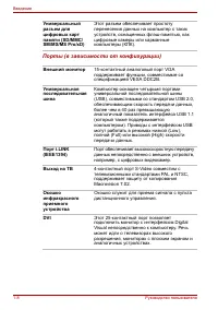
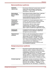
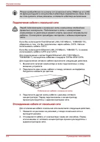
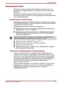
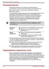
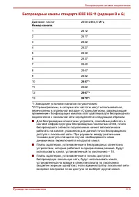
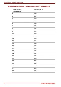
Chapter 1 Hardware Overview 10 Satellite P100 Maintenance Manual(960-Q02) θ Mini Card Wireless LAN card (BTO) 2.4GHz DSSS/OFDM LAN card is equipped. Conformity with IEEE 802.11b/g and IEEE 802.11a/b/g.. Transfer speed maximum is 54Mbit/sec. supports 128bit WEP. θ LAN (Intel) Controls LAN. Intel EP82...
Page 28 - Satellite P100 Maintenance Manual (960-Q02) 11
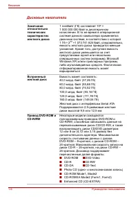
Chapter 1 Hardware Overview 1.3 2.5-inch Hard Disk Drive A compact, high-capacity HDD with a height of 9.5mm. Contains a 2.5-inch magnetic disk and magnetic heads. Figure 1-3 shows a view of the 2.5-inch HDD and Tables 1-1 and 1-2 list the specifications. Figure 1-3 2.5-inch HDD Table 1-1 2.5-inch H...
Page 30 - Satellite P100 Maintenance Manual (960-Q02) 13
Chapter 1 Hardware Overview Satellite P100 Maintenance Manual (960-Q02) 13 Specification Parameter FUJITSU MHV2120B H FUJITSU MHV2100B H FUJITSU MHV2080B H FUJITSU MHV2060B H FUJITSU MHV2040B H FUJITSU MHV2160BT Storage size (formatted) 120GB 100GB 80GB 60GB 40GB 160GB Speed (RPM) 5,400 4,200 Data t...
Page 31 - support
Chapter 1 Hardware Overview Specification Parameter HITACHI HTS541040G9SA00 HITACHI HTS541040G9SA00 HITACHI HTS541040G9SA00 HITACHI HTS541040G9SA00 Storage size (formatted) 40GB 60GB 80GB 100GB Speed (RPM) 5,400 Data transfer speed(Mbits/s) 493 493 493 493 bus transfer rate (MB/s) 150 ATA7/SERIAL AT...
Page 32 - HITACHI; Buffer Size; Satellite P100 Maintenance Manual (960-Q02) 15
Chapter 1 Hardware Overview Specification Parameter HITACHI HTS721060G9AT00 HITACHI HTS721080G9AT00 HITACHI HTS721010G9AT00 Storage size (formatted) 60GB 80GB 100GB Speed (RPM) 7,200 Data transfer speed(Mbits/s) 267-629 bus transfer rate (MB/s) 150 ATA7/SERIAL ATA1.0a/Serial ATAII 1.2 interface supp...
Page 33 - Drive; Parameter Standard; MATSUSHITA
Chapter 1 Hardware Overview 1.4 Optical Drive 1.4.1 DVD-ROM & CD-R/RW Drive The DVD-ROM & CD-R/RW drive accommodates either 12 cm (4.72-inch) or 8 cm (3.15-inch) CD/DVD-ROM and CD-R/RW. It is a high-performance drive that reads DVD at maximum 8-speed and CD at maximum 24-speed. The DVD-ROM &...
Page 34 - Satellite P100 Maintenance Manual (960-Q02) 17
Chapter 1 Hardware Overview Satellite P100 Maintenance Manual (960-Q02) 17 Table 1-4 DVD-ROM & CD-R/RW drive specifications (1/3) Drive Specification Parameter MATSUSHITA (UJDA770TT-A) Read (KB/s) DVD-ROM MAX 8X CAV (MAX 10800 KB/s) CD-ROM MAX 24X CAV (MAX 3600 KB/s) Write CD-R 4X , 8X (CLV), 16...
Page 35 - Drive Specification
Chapter 1 Hardware Overview 18 Satellite P100 Maintenance Manual(960-Q02) Table 1-4 DVD-ROM & CD-R/RW drive specifications (2/3) Drive Specification Parameter HLDS (GCC-4244N.ATAKN0) Read (KB/s) DVD-ROM Single Layer3.3x -8x (CAV):Approx. 4,710 r/min Dual Layer3.3x -8x (CAV): Approx. 5,180 r/min ...
Page 36 - Satellite P100 Maintenance Manual (960-Q02) 19
Chapter 1 Hardware Overview Satellite P100 Maintenance Manual (960-Q02) 19 CD CD-ROM Mode1&2S CD-ROM XA Modo2 (Form1&2) CD-DA, CD-I, CD-Extra/CD-Plus, Video-CD Supported disk format DVD DVD-ROM DVD Video DVD-R (General, Authoring) DVD-RW (Single/Multi-boarder, Packet) DVD-RAM DVD+R/RW
Page 38 - Satellite P100 Maintenance Manual (960-Q02) 21
Chapter 1 Hardware Overview 1.4.2 DVD Super Multi Drive The DVD Super Multi drive accommodates either 12 cm (4.72-inch) or 8 cm (3.15-inch) CD/DVD-ROM, CD-R/RW, DVD±R/±RW and DVD-RAM. It is a high-performance drive that reads DVD-ROM at maximum 8-speed and CD at maximum 24-speed. Write speed of DVD±...
Page 40 - Satellite P100 Maintenance Manual (960-Q02) 23
Chapter 1 Hardware Overview Satellite P100 Maintenance Manual (960-Q02) 23 Table 1-2 DVD Super Multi drive specifications (2/4) Drive Specification Parameter HLDS (GSA-4082N.ATAKN0) Read(KB/s) DVD-R/RW/ROM 8x/8x/8x max. DVD-RAM (Ver.1.0)2x (Ver.2.2)2x, 3x, 5x DVD-Video (CSSCompliant Disc)4x max.(Sin...
Page 42 - Satellite P100 Maintenance Manual (960-Q02) 25
Chapter 1 Hardware Overview Satellite P100 Maintenance Manual (960-Q02) 25 Table 1-6 DVD Super Multi drive specifications (4/4) Drive Specification Parameter TEAC (DV-W28EA) Read(KB/s) 8X CAV at DVD-ROM (Single Layer),DVD-R/ +R 4X CAV at DVD-RW/ +RW 4X CAV at DVD+R (Dual Layer), DVD-R DL and +R DL 3...
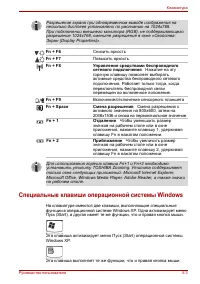
Page 44 - Keyboard; See Appendix E for details of the keyboard layout.; Satellite P100 Maintenance Manual (960-Q02) 27
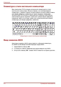
Chapter 1 Hardware Overview 1.5 Keyboard The Satellite P100 comes with a "desktop-style" keyboard built into it. This means it is full-sized and features a full set of numeric function keys (also known as calculator keys) on the right-hand side. Unlike other notebooks computers with smaller ...
Page 45 - TFT Color Display; Module; Item
Chapter 1 Hardware Overview 1.6 TFT Color Display The TFT color display is 17.1 inch and consists of LCD module and FL inverter board. 1.6.1 LCD Module The LCD module used for the TFT color display uses a backlight as the light source and can display with 1,440x 900 dots (WXGA+) or 1,680x1,050 dots(...
Page 46 - Satellite P100 Maintenance Manual (960-Q02) 29; Table 1-10 lists the FL inverter board specifications.; Table 1-8 FL inverter board specifications; Specifications
Chapter 1 Hardware Overview Satellite P100 Maintenance Manual (960-Q02) 29 1.6.2 FL Inverter Board The FL inverter board supplies a high frequency current to illuminate the LCD module FL. Table 1-10 lists the FL inverter board specifications. Table 1-8 FL inverter board specifications Specifications...
Page 47 - Supply
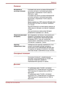
Chapter 1 Hardware Overview 30 Satellite P100 Maintenance Manual(960-Q02) 1.7 Power Supply The power supply supplies 23 different voltages to the system board. The power supply microcontroller has the following functions. 1. Judges if the DC power supply (AC adapter) is connected to the computer. 2....
Page 48 - Satellite P100 Maintenance Manual (960-Q02) 31; Table 1-9 Power supply output rating; Name
Chapter 1 Hardware Overview Satellite P100 Maintenance Manual (960-Q02) 31 Table 1-9 Power supply output rating Power supply ( Yes/No ) Name Voltage [V] Power OFF Suspend mode Power OFF Boot mode No Battery Object VCC_CORE 1.484 - 0.748 No No No CPU VTT 1.05 No No No CPU, 915GM, ICH4-M +1.8V 1.8 No ...
Page 49 - The PC has the following two batteries.; Table 1-10 Battery specifications; Battery Name; Battery
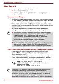
Chapter 1 Hardware Overview 32 Satellite P100 Maintenance Manual(960-Q02) 1.8 Batteries The PC has the following two batteries. θ Main battery θ Real time clock (RTC) battery Table 1-10 lists the specifications for these two batteries. Table 1-10 Battery specifications Battery Name Battery Element O...
Page 50 - Satellite P100 Maintenance Manual (960-Q02) 33; Table 1-11 Time required for charges of main battery; Condition Charging; Table 1-12 Data preservation time; Condition preservation
Chapter 1 Hardware Overview Satellite P100 Maintenance Manual (960-Q02) 33 1.8.2 Battery Charging Control Battery charging is controlled by a power supply microprocessor. The power supply microprocessor controls power supply and detects a full charge when the AC adaptor and battery are connected to ...
Page 51 - Condition Time
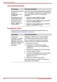
Chapter 1 Hardware Overview 34 Satellite P100 Maintenance Manual(960-Q02) 1.8.3 RTC Battery The RTC battery provides the power supply to maintain the date, time, and other system information in memory. Table 1-13 lists the Time required for charges of RTC battery and data preservation time. Table 1-...
Page 52 - Satellite P100 Maintenance Manual (960-Q02) 35; Adapter; The AC adapter is used to charge the battery.; Table 1-14 AC adapter specifications
Chapter 1 Hardware Overview Satellite P100 Maintenance Manual (960-Q02) 35 1.9 AC Adapter The AC adapter is used to charge the battery. Table 1-14 lists the AC adapter specifications. Table 1-14 AC adapter specifications Parameter Specification With Led DELTA/ LITE-ON DELTA/ LITE-ON DELTA/LITE-ON Po...
Page 54 - -2 [CONFIDENTIAL]
2-2 [CONFIDENTIAL] Satellite P100 Maintenance Manual(960-Q02) 2
Page 56 - -4 [CONFIDENTIAL]
2-4 [CONFIDENTIAL] Satellite P100 Maintenance Manual(960-Q02)
Page 58 - -6 [CONFIDENTIAL]
2-6 [CONFIDENTIAL] Satellite P100 Maintenance Manual(960-Q02)
Page 59 - Troubleshooting Procedures; lue
2 Troubleshooting Procedures Satellite P100 Maintenance Manual (960-Q02) 1 2 2.1 Troubleshooting Chapter 2 describes how to determine which Field Replaceable Unit (FRU) in the computer is causing the computer to malfunction. The FRUs covered are: 1. Power supply 6. Touch pad 11. Wireless LAN 2. Syst...
Page 61 - Flowchart; Ask him or her to enter the password if a password is registered.
2 Troubleshooting Procedures Satellite P100 Maintenance Manual (960-Q02) 3 2.2 Troubleshooting Flowchart Use the flowchart in Figure 2-1 as a guide for determining which troubleshooting procedures to execute. Before going through the flowchart steps, verify the following: Ask him or her to enter t...
Page 65 - Battery icon
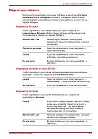
2 Troubleshooting Procedures Satellite P100 Maintenance Manual (960-Q02) 7 2.3 Power Supply Troubleshooting The power supply controller controls many functions and components. To determine if the power supply is functioning properly, start with Procedure 1 and continue with the other Procedures as i...
Page 66 - DC IN icon; When the icon is blinking, perform the following procedure.
2 Troubleshooting Procedures 8 Satellite P100 Maintenance Manual(960-Q02) Table 2-2 DC IN icon DC IN icon Power supply status Lights green DC power is being supplied from the AC adapter. Blinks orange Power supply malfunction *1 Doesn’t light Any condition other than those above. *1 When the power s...
Page 67 - Procedure 2
2 Troubleshooting Procedures Satellite P100 Maintenance Manual (960-Q02) 9 Procedure 2
Page 69 - Check 4
2 Troubleshooting Procedures Satellite P100 Maintenance Manual (960-Q02) 11 Check 4 The battery’s temperature is too high or low. Leave the battery for a while to adjust it in the right temperature. If the battery pack is still not charged, go to Check 5. Check 5 Replace the battery pack with a new ...
Page 71 - Board; Procedure 1: Message Check
2 Troubleshooting Procedures Satellite P100 Maintenance Manual (960-Q02) 13 2.4 System Board Troubleshooting This section describes how to determine if the system board is malfunctioning or not. Start with Procedure 1 and continue with the other procedures as instructed. The procedures described in ...
Page 72 - Check 2; PRESS ANY KEY TO CONTINUE.; If any other error message displays, perform Check 3.
2 Troubleshooting Procedures 14 Satellite P100 Maintenance Manual(960-Q02) Procedure 1 Message Check When the power is turned on, the system performs the Power On Self Test (POST) installed in the BIOS ROM. The POST tests each IC on the system board and initializes it. If an error message is shown...
Page 73 - Check 3
2 Troubleshooting Procedures Satellite P100 Maintenance Manual (960-Q02) 15 Check 3 The IRT checks the system board. When the IRT detects an error, the system stops or an error message appears. If one of the following error messages (1) through (17), (24) or (25) is displayed, go to Procedure 4. If ...
Page 74 - The test procedures are follows:
2 Troubleshooting Procedures Procedure 2 Debugging Port Check Check the MiniPCI Debug board. The tool for debug port test is shown below. Figure 2-2 A set of tool for debug port test The test procedures are follows: 1. Replace Mini PCI debug port with Wireless LAN card, check LED in the Mini PCI deb...
Page 76 - Disable onboard Super I/O ports and IRQs
2 Troubleshooting Procedures 18 Satellite P100 Maintenance Manual(960-Q02) 66h Configure advanced cache registers 67h Initialize Multi Processor APIC 68h Enable external and CPU caches 69h Setup System Management Mode (SMM) area 6Ah Display external L2 cache size 6Bh Load custom defaults (optional) ...
Page 77 - Initialize POST Error Manager (PEM)
2 Troubleshooting Procedures Satellite P100 Maintenance Manual (960-Q02) 19 Code Beeps POST Routine Description AAh Scan for F2 key stroke ACh Enter SETUP AEh Clear Boot flag B0h Check for errors B2h POST done - prepare to boot operating system B4h 1 One short beep before boot B5h Terminate QuietBoo...
Page 80 - USB FDD Troubleshooting; Procedure 1: FDD Head Cleaning Check; Detailed operation is given in Chapter 3,; Tests and Diagnostics
2 Troubleshooting Procedures 22 Satellite P100 Maintenance Manual(960-Q02) 2.5 USB FDD Troubleshooting To check if the USB FDD is malfunctioning or not, follow the troubleshooting procedures below as instructed. Procedure 1: FDD Head Cleaning Check Procedure 2: Diagnostic Test Program Execution Chec...
Page 81 - for more information about the diagnostics test procedures.; Table 2-7 FDD error code and status; Code Status; Check 1
2 Troubleshooting Procedures Satellite P100 Maintenance Manual (960-Q02) 23 Procedure 2 Diagnostic Test Program Execution Check Insert the Diagnostics Disk in the USB FDD, turn on the computer and run the test. Refer to Chapter 3, Tests and Diagnostics, for more information about the diagnostics tes...
Page 82 - and perform the following checks.
2 Troubleshooting Procedures Procedure 3 Connector Check and Replacement Check USB FDD is connected to USB port on system board and US board. US board is also connected to system board by cable. The connection of cable and board may be defective. Otherwise, they may be faulty. Disassemble the comput...
Page 83 - Replacement Procedures
2 Troubleshooting Procedures Satellite P100 Maintenance Manual (960-Q02) 25 Check 2 USB FDD may be faulty. Replace it with a new one. If the problem still occurs, perform Check 3. Check 3 Connect USB FDD to each port embedded on system board. If it does not work properly when connected to CN12, CN19...
Page 85 - HDC ERROR; or; System Transferred
2 Troubleshooting Procedures Satellite P100 Maintenance Manual (960-Q02) 27 Procedure 2 Message Check When the power is turned on, the system performs the Initial Reliability Test (IRT) installed in the BIOS ROM. When the test detects an error, an error message is displayed on the screen. Make sure ...
Page 87 - for more information about; Table 2-8 2.5” Hard disk drive error code and status
2 Troubleshooting Procedures Satellite P100 Maintenance Manual (960-Q02) 29 Procedure 4 Diagnostic Test Program Execution Check The HDD test program is stored in the Diagnostics Disk. Perform all of the HDD tests in the Hard Disk Drive Test. Refer to Chapter 3, Tests and Diagnostics, for more inform...
Page 88 - and perform the following; and check the operation. If the
2 Troubleshooting Procedures Procedure 5 Connector Check and Replacement Check HDD(s) is/are connected to the connector(s) on the system board. The connection of HDD(s) and board may be defective. Otherwise, they may be faulty. Disassemble the computer following instructions in Chapter 4, Replacemen...
Page 89 - Keyboard Troubleshooting; Procedure 1: Diagnostic Test Program Execution Check; information on how to perform the test program.
2 Troubleshooting Procedures Satellite P100 Maintenance Manual (960-Q02) 31 2.7 Keyboard Troubleshooting To check if the computer’s keyboard is malfunctioning or not, follow the troubleshooting procedures below as instructed. Procedure 1: Diagnostic Test Program Execution Check Procedure 2: Connecto...
Page 91 - Touch pad Troubleshooting; , for more information on how to perform the test program.
2 Troubleshooting Procedures Satellite P100 Maintenance Manual (960-Q02) 33 2.8 Touch pad Troubleshooting To check if the computer’s touch pad is malfunctioning or not, follow the troubleshooting procedures below as instructed. Procedure 1: Diagnostic Test Program Execution Check Procedure 2: Connec...
Page 93 - Troubleshooting Procedures; Satellite P100 Maintenance Manual; Display Troubleshooting; Procedure 1: External Monitor Check
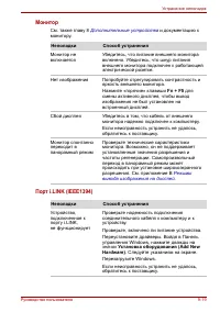
Troubleshooting Procedures Satellite P100 Maintenance Manual 35 2.9 Display Troubleshooting To check if the computer’s display is malfunctioning or not, follow the troubleshooting procedures below as instructed. Procedure 1: External Monitor Check Procedure 2: Diagnostic Test Program Execution Check...
Page 95 - Procedure 4
Troubleshooting Procedures Satellite P100 Maintenance Manual 37 Procedure 4 Replacement Check Fluorescent lamp, FL inverter, LCD module, HV cable and LCD/FL cable are connected to display circuits. Any of these components may be faulty. Refer to Chapter 4, Replacement Procedures, for instructions on...
Page 96 - Optical Disk Drive Troubleshooting
Troubleshooting Procedures 2.10 Optical Disk Drive Troubleshooting To check if optical disk drive is malfunctioning or not, follow the troubleshooting procedures below as instructed. Procedure 1: Diagnostic Test Program Execution Check Procedure 2: Connector Check and Replacement Check Procedure 1 D...
Page 97 - Modem Troubleshooting
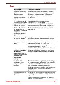
Troubleshooting Procedures 2.11 Modem Troubleshooting To check if modem is malfunctioning or not, follow the troubleshooting procedures below as instructed. Procedure 1: Diagnostic Test Program Execution Check Procedure 2: Connector Check and Replacement Check Procedure 1 Diagnostic Test Program Exe...
Page 99 - LAN Troubleshooting
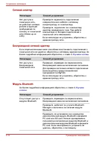
Troubleshooting Procedures 2.12 LAN Troubleshooting To check if the computer’s LAN is malfunctioning or not, follow the troubleshooting procedures below as instructed. Procedure 1: Diagnostic Test Program Execution Check Procedure 2: Connector Check and Replacement Check Procedure 1 Diagnostic Test ...
Page 100 - Wireless LAN Troubleshooting; Procedure 1: Transmitting-Receiving Check
Troubleshooting Procedures 42 Satellite P100 Maintenance Manual 2.13 Wireless LAN Troubleshooting To check if the computer's Wireless LAN is malfunctioning or not, follow the troubleshooting procedures below as instructed. Procedure 1: Transmitting-Receiving Check Procedure 2: Antennas' Connection C...
Page 101 - The wireless LAN function-wiring diagram is shown below:
Troubleshooting Procedures Procedure 2 Antennas' Connection Check The wireless LAN function-wiring diagram is shown below: Any of the connections may be defective. Disassemble the computer following the steps described in Chapter 4, Replacement Procedures , and perform the following checks: Check 1 ...
Page 102 - Procedure 3; for instructions on how to disassemble the computer and then; Check3
Troubleshooting Procedures 44 Satellite P100 Maintenance Manual Procedure 3 Replacement Check Wireless LAN card, wireless LAN antenna or system board may be faulty. Refer to Chapter 4, Replacement Procedures, for instructions on how to disassemble the computer and then perform the following checks: ...
Page 103 - Sound Troubleshooting; Procedure 1: Connector Check; The connection of sound system is shown in the following figure.
Troubleshooting Procedures 2.14 Sound Troubleshooting To check if the sound function is malfunctioning or not, follow the troubleshooting procedures below as instructed. Procedure 1: Connector Check Procedure 2: Replacement Check Procedure 1 Connector Check The connection of sound system is shown in...
Page 105 - VGA Troubleshooting
Troubleshooting Procedures 2.15 VGA Troubleshooting Procedure 1 Diagnostic Test Program Execution Check Execute VGA test in the test program. Refer to Chapter 3, Tests and Diagnostics for more information on how to perform the test program. If any error is detected, perform Procedure 2. Procedure 2 ...
Page 106 - Check 5
Troubleshooting Procedures 48 Satellite P100 Maintenance Manual Check 5 System board may be faulty. Replace it with a new one following the instruction in Chapter 4.
Page 107 - Fingerprint Troubleshooting
Troubleshooting Procedures 2.16 Fingerprint Troubleshooting To check if the computer’s Fingerprint is malfunctioning or not, follow the troubleshooting procedures below as instructed. Procedure 1: Connector Check and Replacement Check Procedure 1 Diagnostic Test Program Execution Check Execute Finge...
Page 108 - Bluetooth Troubleshooting
Troubleshooting Procedures 2.17 Bluetooth Troubleshooting To check if the computer’s B lue tooth is malfunctioning or not, follow the troubleshooting procedure below as instructed. Procedure 1: Connector Check and Replacement Check Procedure 1 Connector Check and Replacement Check The B lue tooth fu...
Page 109 - Test Program for Field.; Chapter 3
Test Program for Field. Satellite P100 and Satellite Pro P100 Tests and Diagnostics Manual 1 Chapter 3 Diagnostic Programs
Page 110 - Chapter 3 Contents
Test Program for Field. 2 Satellite P100 and Satellite Pro P100 Tests and Diagnostics Manual Chapter 3 Contents 3.1 Tests and Diagnostics Software Overview ............................................................ 3-3 3.2 Executing the Diagnostic Test ................................................
Page 111 - Tests and Diagnostics Software Overview; NOTES: Before starting the Tests and Diagnostics software:
Test Program for Field. Satellite P100 and Satellite Pro P100 Tests and Diagnostics Manual 3 3.1 Tests and Diagnostics Software Overview This chapter explains how to use the Tests and Diagnostics Software for the Satellite P100 and Satellite Pro P100 computer systems. NOTES: Before starting the Test...
Page 112 - Executing the Diagnostic Test; The following screen displays:
Test Program for Field. 4 Satellite P100 and Satellite Pro P100 Tests and Diagnostics Manual 3.2 Executing the Diagnostic Test DOS is required to run the Diagnostics Program. To start the programs follow these steps: 1. Create a DOS bootable disk and copy all the files from the Tests and Diagnostics...
Page 113 - The following menu displays:
Test Program for Field. Satellite P100 and Satellite Pro P100 Tests and Diagnostics Manual 5 The following menu displays: :Select item Enter:Decision item Esc:Escape TOSHIBA Satellite(Pro) P100 Diagnostics Version V1.00 (C) Copyright QUANTA Corp. 2005- [ DIAGNOSTICS MENU ] 01. DIAGNOSTIC TEST 02. RU...
Page 116 - names; Test Name
Test Program for Field. 8 Satellite P100 and Satellite Pro P100 Tests and Diagnostics Manual 3.3 Subtest names Table 3-1 lists the subtest names for each test program in the Diagnostic Test menu. Table 3-1 Subtest Names(1/3) No. Test Name No. Subtest Name 01 SYSTEM TEST 01 02 03 04 05 FAN ON/OFF che...
Page 119 - Test; Fan2 Status On Fan2RPM : 4000 or Fan2 Status OFF Fan2RPM : 0
Test Program for Field. Satellite P100 and Satellite Pro P100 Tests and Diagnostics Manual 11 3.4 System Test To execute the System Test select 01 from the Diagnostic Test Menu, press Enter and follow the directions on the screen. The System Test contains two subtests. Move the highlight bar to the ...
Page 120 - CPU Temperature; NOTE: Execution of this program destroys fingerprint data .
Test Program for Field. 12 Satellite P100 and Satellite Pro P100 Tests and Diagnostics Manual Subtest 03 CPU Temperature This will display CPU Temperature for check , press [ESC] to exit . [CPU_TEMP.EXE] Program Version : 1.0 08-08-2005 CPU Temperature : XX Subtest 04 CIR Remote Control Test When yo...
Page 121 - Conventional Memory
Test Program for Field. Satellite P100 and Satellite Pro P100 Tests and Diagnostics Manual 13 3.5 Memory Test To execute the Memory Test select 02 from the Diagnostic Test Menu, press Enter and follow the directions on the screen. The Memory Test contains five subtests that test the computer’s memor...
Page 122 - Protected Mode
Test Program for Field. 14 Satellite P100 and Satellite Pro P100 Tests and Diagnostics Manual 5. Address pattern test “16 bit write and 16 bit read” of address pattern data is executed and the new data is compared with the original data. Test data = 0000H, 0004H, 0008H, 000CH,...8000H, 8004H, throug...
Page 123 - Tests memory addresses 0 to the maximum installed.
Test Program for Field. Satellite P100 and Satellite Pro P100 Tests and Diagnostics Manual 15 Test Process: 1. Checks the memory size to determine the maximum size of installed memory. 2. Tests memory addresses 0 to the maximum installed. 3. Writes, reads, and compares test data after a memory refre...
Page 125 - Keyboard LED
Test Program for Field. Satellite P100 and Satellite Pro P100 Tests and Diagnostics Manual 17 Subtest 03 Hot Key Display [6 Key] This subtest is used for the 6 hot key and functions the same as Subtest 1. Subtest 04 Hot Key Display [7 Key] This subtest is used for the 7 hot key and functions the sam...
Page 126 - PRESS
Test Program for Field. 18 Satellite P100 and Satellite Pro P100 Tests and Diagnostics Manual LEFT PRESS RIGHT PRESS TOUCH_PAD TEST Please Do Not Press the Left and Right Button At The Same Time
Page 127 - Character Attributes
Test Program for Field. Satellite P100 and Satellite Pro P100 Tests and Diagnostics Manual 19 3.7 Display Test To execute the Display Test select 04 from the Diagnostic Test Menu, press Enter and follow the directions displayed on the screen. The Display Test contains twelve subtests that test the d...
Page 131 - To exit this subtest and return to the Display Test menu:; on the Test Parameter Menu.; Test Loop; on the Test Parameter
Test Program for Field. Satellite P100 and Satellite Pro P100 Tests and Diagnostics Manual 23 Press ENTER to display 64 gradations of red, green, blue and white on the screen To exit this subtest and return to the Display Test menu: Press Enter if NO was selected for Test Loop on the Test Parameter ...
Page 138 - Color Attributes Display
Test Program for Field. 30 Satellite P100 and Satellite Pro P100 Tests and Diagnostics Manual Subtest 11 Color Attributes Display This subtest displays 16 colors: black, blue, green, cyan, red, magenta, brown, white, dark gray, light blue, light green, light cyan, light red, light magenta, yellow, a...
Page 139 - Press Enter to display VRAM mapping test using the all dots Mode.
Test Program for Field. Satellite P100 and Satellite Pro P100 Tests and Diagnostics Manual 31 NOTE: The following screen does not display correctly. It will be amended in the next version. Press Enter to execute the VRAM mapping test which displays a vertical line at four dot intervals using Mode 12...
Page 142 - Floppy Disk Test; Sequential Read
Test Program for Field. 34 Satellite P100 and Satellite Pro P100 Tests and Diagnostics Manual 3.8 Floppy Disk Test CAUTION: Before running the floppy disk test, prepare a formatted work disk. Remove the diagnostics disk and insert the work disk into the FDD. The contents of the floppy disk will be e...
Page 143 - Write Specified Address
Test Program for Field. Satellite P100 and Satellite Pro P100 Tests and Diagnostics Manual 35 Subtest 04 Write Specified Address NOTE: The first two digits of the ADDRESS indicate which track is being tested, the next two digits indicates the head, and the last two digits indicate the sector. This s...
Page 145 - Cross Talk and Peak Shift; TEST DATA; Read Specified Address
Test Program for Field. Satellite P100 and Satellite Pro P100 Tests and Diagnostics Manual 37 Subtest 04 Cross Talk and Peak Shift This subtest writes eight of the most likely to fail data patterns (shown below) to a cylinder on the HDD, then reads the data while moving from cylinder to cylinder. Da...
Page 146 - Sequential Write
Test Program for Field. 38 Satellite P100 and Satellite Pro P100 Tests and Diagnostics Manual Subtest 07 Sequential Write This subtest writes specified data to all cylinders on the HDD. The following message displays on the screen to enter the test data. TEST DATA ????(=37b3H) Subtest 08 W-R-C Speci...
Page 147 - Real Time Clock Test
Test Program for Field. Satellite P100 and Satellite Pro P100 Tests and Diagnostics Manual 39 3.10 Real Time Clock Test To execute the Real Time Clock Test select 07 from the Diagnostic Test Menu, press Enter and follow the directions on the screen. The Real Time Clock Test contains three subtests t...
Page 149 - Cache Memory Test; Constant Data Test
Test Program for Field. Satellite P100 and Satellite Pro P100 Tests and Diagnostics Manual 41 3.11 Cache Memory Test To execute the Cache Memory Test select 08 from the Diagnostic Test Menu, press Enter and follow the directions on the screen. The Cache Memory Test contains eight subtests that test ...
Page 151 - High Resolution Display Test
Test Program for Field. Satellite P100 and Satellite Pro P100 Tests and Diagnostics Manual 43 3.12 High Resolution Display Test To execute the High Resolution Display Test select 09 from the Diagnostic Test Menu, press Enter and follow the directions on the screen. The High Resolution Display Test c...
Page 152 - Enter if NO was selected for
Test Program for Field. 44 Satellite P100 and Satellite Pro P100 Tests and Diagnostics Manual [ 640*480 256 ] Press [ Enter ]key 0---+---1---+---2---+---3---+---4---+---5---+---6--- 256 letter types indication WHITE RED GREEN BLUE Subtest 02 640*480 Mode Display This subtest uses 640*480 video resol...
Page 157 - Multimedia Test; Sequential Read Test
Test Program for Field. Satellite P100 and Satellite Pro P100 Tests and Diagnostics Manual 49 3.13 Multimedia Test To execute the Multimedia Test select 10 from the Diagnostic Test Menu, press Enter and follow the directions on the screen. The Multimedia Test contains four subtests that test the com...
Page 158 - All one/All zero test
Test Program for Field. 50 Satellite P100 and Satellite Pro P100 Tests and Diagnostics Manual 3.14 MEMORY2 Test To execute the Expansion Test select 11 from the Diagnostic Test Menu, press Enter and follow the directions on the screen. The MEMORY2 Test contains four subtests that test the computer's...
Page 160 - Error Codes and Error Status Names; Device Name
Test Program for Field. 52 Satellite P100 and Satellite Pro P100 Tests and Diagnostics Manual 3.15 Error Codes and Error Status Names The following table lists the error codes and error status names for the Diagnostic Tests. Table 3-2 Error codes and error status names (1/2) Device Name Error Code E...
Page 162 - Count Loop; number selected in the
Test Program for Field. 54 Satellite P100 and Satellite Pro P100 Tests and Diagnostics Manual 3.16 Running Test NOTES: 1. You may add or delete subtests using the Running Test Edit Item function, see Section 3.20. 2. Do not forget to insert a work disk in the FDD. If a work disk is not inserted an e...
Page 163 - DMI INFOEMATION; NOTE: Please set the media of DVD before starting a test.
Test Program for Field. Satellite P100 and Satellite Pro P100 Tests and Diagnostics Manual 55 3.17 DMI INFOEMATION Select 03 from the Diagnostics Menu and press Enter to Check or Write DMI Information Data: 3.17.1 Check DMI Information The Check DMI Configuration program contains the following confi...
Page 167 - System Configuration; SYSTEM CONFIGURATION :
Test Program for Field. Satellite P100 and Satellite Pro P100 Tests and Diagnostics Manual 59 3.19 System Configuration Select 05 from the Diagnostics Menu and press Enter to display the following system configuration: SYSTEM CONFIGURATION : * - BIOS VER = VX.XX KBC VER = XXXX * - MAC ADDRESS : XXXX...
Page 168 - Running Test Edit Item
Test Program for Field. 60 Satellite P100 and Satellite Pro P100 Tests and Diagnostics Manual 3.20 Running Test Edit Item 3.20.1 Function Description Function description lets you add or delete the subtests used to execute the Running Test. The following screen displays after pressing the Tab key to...
Page 169 - Save to disk
Test Program for Field. Satellite P100 and Satellite Pro P100 Tests and Diagnostics Manual 61 1. Enter a number or 0 for Loop Count and press Enter. Select a number from 1 to 65535 to define the number of times the Running Test executes. Select 0 to run the test continuously until halted by the user...
Page 170 - Common Tests and Operation; To input parameters, or open a window use the following keys.; Displays the name of the test being executed.
Test Program for Field. 62 Satellite P100 and Satellite Pro P100 Tests and Diagnostics Manual 3.21 Common Tests and Operation 3.21.1 How to operate a window To input parameters, or open a window use the following keys. key : to move a highlight bar [Enter] key : to select an item at the highlight ba...
Page 172 - The three selections have the following functions:
Test Program for Field. 64 Satellite P100 and Satellite Pro P100 Tests and Diagnostics Manual 3.21.4 Test Stop Display If an error occurs during a Subtest and YES is selected for Error Stop, the following message displays: * Select 1, 2, or 3 The three selections have the following functions: 1: Ter...
Page 174 - Satellite
Replacement Procedures 4-ii Satellite P100 Maintenance Manual (960-Q02) 4
Page 175 - disk
Replacement Procedures Satellite P100 Maintenance Manual (960-Q02) 4-iii Chapter 4 Contents 4.1 Overview .................................................................................................................... 4-1 Safety Precautions ..........................................................
Page 176 - Figures
Replacement Procedures 4-iv Satellite P100 Maintenance Manual (960-Q02) Figures Figure 4-1 Removing the battery pack................................................................................. 4-8 Figure 4-2-1 Removing a PC card .....................................................................
Page 179 - Safety Precautions
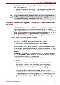
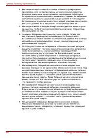
Replacement Procedures 4-2 Satellite P100 Maintenance Manual (960-Q02) Safety Precautions Please read the following safety instructions before disassembling the computer and always follow the instructions while working on the computer. DANGER: 1. In the case of the battery, always use authentic part...
Page 181 - Three main types of cable connector are used.; Pressure plate connector
Replacement Procedures 4-4 Satellite P100 Maintenance Manual (960-Q02) Disassembly Procedure Three main types of cable connector are used. • Pressure plate connector • Spring connector • Normal pin connector When disconnecting a pressure plate connector, lift up the tag on one side of the plastic pr...
Page 182 - Check that all cables and connectors are securely connected.; Tools and Equipment; One Philips screwdriver with type 0 bit (for THIN HEAD screws)
Replacement Procedures Satellite P100 Maintenance Manual (960-Q02) 4-5 Assembly Procedure After the computer has been disassembled and the part that caused the fault has been repaired or replaced, the computer must be reassembled. Take note of the following general points when assembling the compute...
Page 183 - Use the following torque when tightening screws.; Grip Color; Even numbered length screws: Brown
Replacement Procedures 4-6 Satellite P100 Maintenance Manual (960-Q02) Screw Tightening Torque Use the following torque when tightening screws. CAUTION: Overtightening may damage screws or parts. Undertightening may allow screws to loosen (and possibly fall out) causing a short circuit or other dama...
Page 184 - Screw shape
Replacement Procedures Satellite P100 Maintenance Manual (960-Q02) 4-7 Screw Notation To make maintenance of the computer easier, markings of the kinds of the screws including the types and lengths of the screws are indicated on the computer body. Format: Screw shape + Screw length (mm) Screw shape ...
Page 185 - pack; Removing the battery pack; Turn off the power of the computer.; Figure 4-1 Removing the battery pack; Latch 2
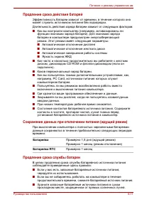
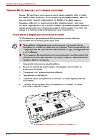
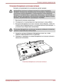
Replacement Procedures 4-8 Satellite P100 Maintenance Manual (960-Q02) 4.2 Battery pack Removing the battery pack The following describes the procedure for removing the battery pack (See Figure 4-1). CAUTION: Take care not to short circuit the terminals when removing the battery pack. Similarly, do ...
Page 187 - card; manual or the manuals of the computer system you are using.; Grasp one of PC card and remove it.; to push a PC card firmly and press the eject button again.; Eject Button1
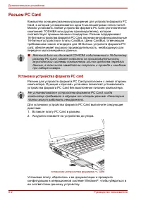
Replacement Procedures 4-10 Satellite P100 Maintenance Manual (960-Q02) 4.3 PC card Removing a PC card The following describes the procedure for removing a PC card (See Figure 4-2-1). CAUTION: Insert or remove a PC card in accordance with any instructions in a PC card manual or the manuals of the co...
Page 188 - Make sure the eject button does not stick out.
Replacement Procedures Satellite P100 Maintenance Manual (960-Q02) 4-11 Installing a PC card The following describes the procedure for inserting a PC card (See Figure 4-2-2). 1. Make sure the eject button does not stick out. 2. Insert a PC card and press it until it is securely connected. Figure 4-2...
Page 189 - Turn the computer upside down.
Replacement Procedures 4-12 Satellite P100 Maintenance Manual (960-Q02) 4.4 HDD Removing a HDD The following describes the procedure for removing a HDD (See Figure 4-3 to 4-4). CAUTION: Take care not to press on the top or bottom of a HDD. Pressure may cause data loss or damage to the device. 1. Tur...
Page 191 - FLAT BIND screw; Figure 4-4 Removing a HDD
Replacement Procedures 4-14 Satellite P100 Maintenance Manual (960-Q02) 5. Remove the following screws securing the HDD holder and remove the HDD holder. • M3.0 × 3.5B FLAT BIND screw x4 Figure 4-4 Removing a HDD HDD holder HDD M3.0x3.5 FLAT BIND
Page 192 - four screws securing the HDD holder.; Secure the HDD assembly with the following screw.
Replacement Procedures Satellite P100 Maintenance Manual (960-Q02) 4-15 Installing a HDD The following describes the procedure for installing a HDD (See Figure 4-3 to 4-4). 1. Install a HDD to the HDD holder and secure it with the following screws. • M3.0 × 3.5F FLAT BIND screw x4 NOTE: Although the...
Page 193 - Wireless LAN card; Removing a Wireless LAN card; screw; Figure 4-5 Removing a wireless LAN card
Replacement Procedures 4-16 Satellite P100 Maintenance Manual (960-Q02) 4.5 Wireless LAN card Removing a Wireless LAN card The following describes the procedure for removing a Wireless LAN card (See Figure 4-5). 1. Remove the following screw of wireless cover securing wireless LAN card cover and rem...
Page 195 - module; Do not touch memory module terminals. Any dirt on the terminals may; Loose the screw securing the memory slot cover.
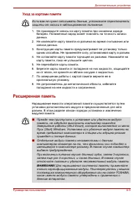
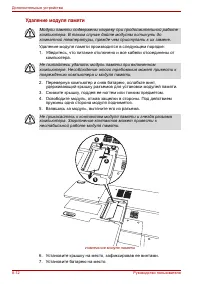
Replacement Procedures 4-18 Satellite P100 Maintenance Manual (960-Q02) 4.6 Memory module CAUTION: The power of the computer must be turned off when you remove a memory module. Removing a memory module with the power on risks damaging the module or the computer itself. Do not touch memory module ter...
Page 197 - Install the memory slot cover and secure it with the screw.; Figure 4-7 Insert a memory module; Socket1
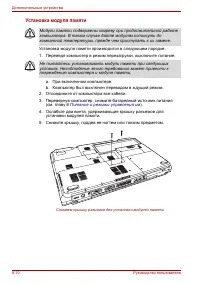
Replacement Procedures 4-20 Satellite P100 Maintenance Manual (960-Q02) Installing a memory module To install a memory module, confirm that the computer is in boot mode. Then perform the following procedure (See Figure 4-7). 1. Insert a memory module into the connector of the computer slantwise (ter...
Page 198 - urn the computer upside down
Replacement Procedures Satellite P100 Maintenance Manual (960-Q02) 4-21 4.7 Keyboard Removing the keyboard The following describes the procedure for removing the keyboard (See Figure 4-8 to 4-9). CAUTION: As the keycap may fall out, when handling the keyboard always hold it by the frame and do not t...
Page 201 - Function Button Board; Removing the Function Board; Remove the following screw securing the switch membrane.; Figure 4-10 Removing the Function board
Replacement Procedures 4-24 Satellite P100 Maintenance Manual (960-Q02) 4.8 Function Button Board Removing the Function Board The following describes the procedure for removing the Function board (See Figure 4-10). 1. Remove the following screw securing the switch membrane. • M2.5 × 3.0B FLAT BIND s...
Page 202 - Press Function board in the computer.
Replacement Procedures Satellite P100 Maintenance Manual (960-Q02) 4-25 Installing the Function Board The following describes the procedure for installing the switch membrane. 1. Press Function board in the computer. 2. Secure the Function board with the following screw. • M2.5 × 3.0B FLAT BIND scre...
Page 203 - Removing an optical disk drive; B FLAT BIND screw; Figure 4-11 Removing an optical disk drive
Replacement Procedures 4-26 Satellite P100 Maintenance Manual (960-Q02) 4.9 Optical disk drive NOTE: Do not apply excessive force to the top of an optical disk drive. Do not touch the shaded portion of the figure below, when the drive is removed or installed. Removing an optical disk drive The follo...
Page 204 - Flat BIND screw
Replacement Procedures Satellite P100 Maintenance Manual (960-Q02) 4-27 Figure 4-12 Disassembling the side bracket Installing an optical disk drive The following describes the procedure for installing an optical disk drive (See Figure 4-11 and 4-12). 1. Attach the ODD bracket to an optical disk driv...
Page 205 - Display assembly; Removing the display assembly; Close the display and turn the computer upside down.
Replacement Procedures 4-28 Satellite P100 Maintenance Manual (960-Q02) 4 4.10 Display assembly Removing the display assembly The following describes the procedure for removing the display assembly (See Figure 4-13 to 4-17). 1. Close the display and turn the computer upside down. 2. Open the MINIPCI...
Page 206 - Open the display and removing the k/b cover and keyboard.; Figure 4-25 Removing the Wireless Antenna and Bluetooth
Replacement Procedures Satellite P100 Maintenance Manual (960-Q02) 4-29 3. Open the display and removing the k/b cover and keyboard. Figure 4-14 Removing keyboard cover 4. Disassembly Function board and pull out the wireless LAN antenna and LCD cables from the guide, If there was Bluetooth Antenna, ...
Page 207 - Opening the display to 180 degree, and remove the hinge screw .; Figure 4-36 Removing the hinge screw
Replacement Procedures 4-30 Satellite P100 Maintenance Manual (960-Q02) 4. Opening the display to 180 degree, and remove the hinge screw . ‧ M2.5 × 6.0 FLAT BIND screw x4 (Locktight) . . Figure 4-36 Removing the hinge screw M2.5x6.0 FLAT BIND (Locktight) M2.5x6.0 FLAT BIND (Locktight)
Page 209 - Installing the display assembly
Replacement Procedures 4-32 Satellite P100 Maintenance Manual (960-Q02) Installing the display assembly The following describes the procedure for installing the display assembly (See Figure 4-13 to 4-17). 1. Inserting the pole of hinge to the hole of hinge assembly, set the display assembly on the b...
Page 210 - Removing the Bluetooth; Figure 4-18 Removing the Bluetooth; Fix the below screw
Replacement Procedures Satellite P100 Maintenance Manual (960-Q02) 4-33 4.11 Bluetooth The following describes for installing the display assembly (See Figure 4-18). Removing the Bluetooth 1. Pull out the Bluetooth cable connect from Bluetooth board 2. Loose the below screw and pull out the MB->B...
Page 211 - Removing the cover assembly
Replacement Procedures 4-34 Satellite P100 Maintenance Manual (960-Q02) 4.12 Cover assembly Removing the cover assembly The following describes the procedure for removing the cover assembly (See Figure 4-19 to 4-21). 1. Turn over the computer. 2. Remove the following screws securing the cover assemb...
Page 213 - Pull up and remove the cover assembly from the base assembly.; Figure 4-21 Removing the cover assembly
Replacement Procedures 4-36 Satellite P100 Maintenance Manual (960-Q02) 4. Pull up and remove the cover assembly from the base assembly. Figure 4-21 Removing the cover assembly Cover assembly Base assembly Cable drain
Page 214 - Install the cover assembly to the base assembly.
Replacement Procedures Satellite P100 Maintenance Manual (960-Q02) 4-37 Installing the cover assembly The following describes the procedure for installing the cover assembly (See Figure 4-19 to 4-21). 1. Install the cover assembly to the base assembly. NOTE: Be careful not to catch the cables betwee...
Page 215 - Removing the touch pad; Remove the following screws securing the touch pad plate.; Figure 4-22 Removing the touch pad; Touch pad
Replacement Procedures 4-38 Satellite P100 Maintenance Manual (960-Q02) 4.13 Touch pad Removing the touch pad The following describes the procedure for removing the touch pad (See Figure 4-22). 1. Peel off the glass tape and disconnect the touch pad flat cable from the connector on the touch pad and...
Page 216 - Stick and install the touch pad on the cover assembly.
Replacement Procedures Satellite P100 Maintenance Manual (960-Q02) 4-39 Installing the touch pad The following describes the procedure for installing the touch pad (See Figure 4-22). 1. Peel off the separator covering on the sensor portion of a new touch pad. NOTE: Do not reuse the touch pad so that...
Page 217 - Removing the audio board; Pull out the audio board cable from audio board connect CN4; Figure 4-23 Removing the Audio Board; Fix the below screws
Replacement Procedures 4-40 Satellite P100 Maintenance Manual (960-Q02) 4.14 Audio Board The following describes for removing the cover assembly (See Figure 4-23). Removing the audio board 1. Pull out the audio board cable from audio board connect CN4 2. Loose the below screws and then incline pull ...
Page 218 - Pull out the fingerprint cable from connect CN5; Figure 4-24 Removing the Fingerprint; Turn over top case and put fingerprint in correct location
Replacement Procedures Satellite P100 Maintenance Manual (960-Q02) 4-41 4.15 Fingerprint The following describes for removing the cover assembly (See Figure 4-24). Remove the Fingerprint 1. Pull out the fingerprint cable from connect CN5 2. Loose below screws from fingerprint board and take it out t...
Page 219 - Removing USB board; Remove the USB cable from CN4 and USBCN1; Figure 4-25 Removing the USB board; Put USB board in correct location and fix below screw
Replacement Procedures 4-42 Satellite P100 Maintenance Manual (960-Q02) 4.16 USB Board The following describes for removing the cover assembly (See Figure 4-25). Removing USB board 1. Remove the USB cable from CN4 and USBCN1 2. Loose below screw from USB board z M2.5x4.0 FLAT BIND screw x1 Figure 4-...
Page 223 - Secure the system board with the following screws.
Replacement Procedures 4-46 Satellite P100 Maintenance Manual (960-Q02) Installing the system board The following describes the procedure for installing the system board (See Figure 4-26). 1. Secure the system board with the following screws. • M2.5 × 4.0 BIND screw x3 2. Connect the speaker cable t...
Page 224 - BIND; order of the number marked on the holder.; Remove the CPU heat sink.; Removing the CPU heat sink
Replacement Procedures Satellite P100 Maintenance Manual (960-Q02) 4-47 4.18 CPU Removing the CPU heat sink The following describes the procedure for removing the CPU heat sink (See Figure 4-27 ). 1. Disconnect the Heat sink cable from the connector CN20 on the system board 2. Remove the following s...
Page 225 - counterclockwise with a flat-blade screwdriver.; Removing the CPU; Check that the mark of cam is in the unlocking position.
Replacement Procedures 4-48 Satellite P100 Maintenance Manual (960-Q02) 4. Unlock the CPU by rotating the cam on the CPU socket 120 degrees to the counterclockwise with a flat-blade screwdriver. 5. Remove the CPU. Figure 4-28 Removing the CPU Installing the CPU The following describes the procedure ...
Page 226 - the number marked on the holder.
Replacement Procedures Satellite P100 Maintenance Manual (960-Q02) 4-49 NOTE: Apply the silicon grease enough to cover the chip surface using the special applicator. Figure 4-29 Applying silicon grease 5. Install the CPU heat sink and heat sink holder and secure them with the following screws along ...
Page 227 - Remove the following screws securing the VGA heat sink along 1 to 5.; Removing the VGA heat sink
Replacement Procedures 4-50 Satellite P100 Maintenance Manual (960-Q02) 4.19 VGA heat sink Removing the VGA heat sink The following describes the procedure for removing the VGA heat sink (See Figure 4-30). 1. Remove the following screws securing the VGA heat sink along 1 to 5. • M2.5 × 3.0 BIND scre...
Page 228 - Install the VGA heat sink.
Replacement Procedures Satellite P100 Maintenance Manual (960-Q02) 4-51 Installing the VGA heat sink The following describes the procedure for installing the VGA heat sink (See Figure 4-30). 1. Install the VGA heat sink. NOTE: For details on applying the silicon grease, refer to Installing the CPU. ...
Page 229 - Remove Screw rubber cover X4; Removing the display mask
Replacement Procedures 4-52 Satellite P100 Maintenance Manual (960-Q02) 4.20 LCD unit / FL inverter CAUTION: When replacing a LCD, it is required that SVP parameter is set. Update with the latest EC/KBC as described in Appendix H “EC/KBC Rewrite Procedures”. Removing the LCD unit / FL inverter The f...
Page 230 - Remove the FL inverter while peeling off the double-sided tape.; Removing the FL inverter; FL inverter
Replacement Procedures Satellite P100 Maintenance Manual (960-Q02) 4-53 4. Pull out one insulator and peel off the other one adhered to the FL inverter. 5. Disconnect the LCD harnesses from the connectors CN1 on the FL inverter. 6. Disconnect the HV harnesses from the connectors CN2 on the FL invert...
Page 231 - Remove the following screws securing the LCD unit.; Removing the LCD unit
Replacement Procedures 4-54 Satellite P100 Maintenance Manual (960-Q02) 8. Remove the following screws securing the LCD unit. • M2.5x4.0 BINK HEAD screw x6 9. With the bottom edge of the LCD unit on the display cover, lift only the top edge of the LCD unit. After peeling off the CONDUTIVE tape, disc...
Page 232 - BINK; Removing the LCD supports
Replacement Procedures Satellite P100 Maintenance Manual (960-Q02) 4-55 11. Remove the following screws securing the LCD support (LCD unit side) and remove the LCD supports from the LCD unit. • M2.0x3.0 BINK screw x4 Figure 4-34 Removing the LCD supports M2.0x3.0 BINK LCD support M2.0x3.0 BINK LCD s...
Page 236 - Appendix Contents
QOSMIO G10 Maintenance Manual (960-497) App-iii Appendix Contents Appendix A Handling the LCD Module .......................................................................... A-1 Appendix B Board Layout ............................................................................................... ...
Page 240 - Appendix A Handling the LCD Module; Precautions for handling the LCD module
Satellite P100 Maintenance Manual(960-Q0 2 ) A-1 Appendix A Appendix A Handling the LCD Module Precautions for handling the LCD module The LCD module can be easily damaged during assembly or disassembly. Observe the following precautions when handling the LCD module: 1. When installing the LCD modul...
Page 241 - Handling the LCD Module
Handling the LCD Module 3. If the panel’s surface gets dirty, wipe it with cotton or a soft cloth. If it is still dirty, try breathing on the surface to create a light condensate and wipe it again. If the surface is very dirty, we recommend a CRT cleaning agent. Apply the agent to a cloth and then w...
Page 246 - Appendix B Board Layout
Satellite P100 Maintenance Manual (960-Q02) B-1 Appendix B Appendix B Board Layout B.1 System Board Figure B-1 System board layout (front)
Page 249 - Button; Figure B-3 Function Button board layout
Board Layout B.2 Function Button board <Front layout> <Back layout> Figure B-3 Function Button board layout Table B-2 Function Button board connectors B-4 Satellite P100 Maintenance Manual(960-Q02)
Page 250 - Board Layout; board; Figure B-3 Modem board layout
Board Layout B.3 Modem board <Front layout> <Back layout> Figure B-3 Modem board layout Table B-3 Modem board connectors Satellite L20 Maintenance Manual(960-Q01) B-5
Page 251 - Touch Pad Board; Figure B-4 Touch pad board layout
Board Layout B.4 Touch Pad Board <Front layout> <Back layout> Figure B-4 Touch pad board layout Table B-4 Touch pad board connectors B-6 Satellite P100 Maintenance Manual(960-Q02)
Page 252 - Figure B-5 Audio board layout
Board Layout B.5 Audio Board <Front layout> <Back layout> Figure B-5 Audio board layout Satellite L20 Maintenance Manual(960-Q01) B-7
Page 256 - Figure B-7 Fingerprint board layout
Board Layout B.7 Fingerprint Board <Front layout> <Back layout> Figure B-7 Fingerprint board layout Table B-7 Fingerprint board connectors Satellite L20 Maintenance Manual(960-Q01) B-11
Page 257 - USB Board; Figure B-8 USB board layout
Board Layout B.8 USB Board <Front layout> <Back layout> Figure B-8 USB board layout Table B-8 USB board connectors B-12 Satellite P100 Maintenance Manual(960-Q02)
Page 258 - Appendix C Pin Assignment; CN1 Bluetooth Connector; CN2 LCD Panel Connector; Signal name
Satellite L10 Maintenance Manual(960-Q01) 1 Appendix C Pin Assignment CN1 Bluetooth Connector CONN SMD FFC 20P 1R FR (P0.5, H2.0) PIN No. Signal name I/O PIN No. Signal name I/O 1 +3V --- 2 NC --- 3 WCS_DAT --- 4 USBP- I/O 5 USBP+ I/O 6 NC --- 7 WCS_CLK --- 8 NC --- 9 NC --- 10 GND --- 11 NC --- 12 ...
Page 259 - CN3 Button Board Connector
Pin Assignment 2 Satellite P100 Maintenance Manual(960-Q02) 7 LVDS_TXL#2 I 8 LVDS_TXL2 I 9 GND --- 10 LVDS_TXL#1 I 11 LVDS_TXL1 I 12 GND --- 13 LVDS_TXL#0 I 14 LVDS_TXL0 I 15 GND --- 16 LVDS_TXLCK# I 17 LVDS_TXLCK I 18 GND --- 19 PNL_CLK I/O 20 PNL_DAT I/O 21 LVDS_TXU#2 I 22 LVDS_TXU2 I 23 GND --- 2...
Page 260 - Pin Assignment; CN4 USB Board Connector
Pin Assignment Satellite P100 Maintenance Manual(960-Q02) 3 PIN No. Signal name I/O PIN No. Signal name I/O 1 NBSWON# O 2 BT1# O 3 BT2# O 4 BT3# O 5 BT4# O 6 BT_IE# O 7 BT_WWW# O 8 CAPSLED I 9 NUMLED I 10 SCRLED I 11 EMAIL_LED I 12 NC --- 13 NC --- 14 NC --- 15 NC --- 16 NC --- 17 GND --- 18 GND ---...
Page 261 - CN5 Finger Print Board Connector; CN6 Internal K/B Connector
Pin Assignment 4 Satellite P100 Maintenance Manual(960-Q02) CN5 Finger Print Board Connector CONN SMD HOUSING 6P 1R FR (P1.25, H1.85) EP PIN No. Signal name I/O PIN No. Signal name I/O 1 +3VSUS --- 2 +3VSUS --- 3 BUSBP+ I/O 4 BUSBP- I/O 5 GND --- 6 GND --- CN6 Internal K/B Connector CONN SMD FPC 26P...
Page 262 - CN7 Touchpad Board Connector
Pin Assignment Satellite P100 Maintenance Manual(960-Q02) 5 CN7 Touchpad Board Connector CONN SMD FFC 6P 1R FR (P1.0, H1.95) PIN No. Signal name I/O PIN No. Signal name I/O 1 +5V_TP --- 2 +5V_TP --- 3 TPDATA I/O 4 TPCLK I/O 5 GND --- 6 GND --- CN8 RTC Battery Connector CONN SMD HEADER 2P MS (P1.25) ...
Page 264 - CN10 Speaker Connector
Pin Assignment Satellite P100 Maintenance Manual(960-Q02) 7 59 A_CSERR# I 60 A_CREQ# I 61 A_CC/BE3# O 62 A_CAUDIO I 63 A_CSTSCHG I 64 A_CAD28 I/O 65 A_CAD30 I/O 66 A_CAD31 I/O 67 A_CCD2# I/O 68 GND --- CN10 Speaker Connector CONN SMD HD 4P 1R MR (P1.25, H3.2) PIN No. Signal name I/O PIN No. Signal n...
Page 265 - CN13 DVI Connector
Pin Assignment 8 Satellite P100 Maintenance Manual(960-Q02) CONN DIP D-SUB 15P 2R FR (P0.76) L-F PIN No. Signal name I/O PIN No. Signal name I/O 1 CRT_R I 2 CRT_G I 3 CRT_B I 4 NC --- 5 GND --- 6 GND --- 7 GND --- 8 GND --- 9 +5V_CRT --- 10 GND --- 11 CRT_SENSE# O 12 CRTDDAT I 13 CRTHSYNC I 14 CRTVS...
Page 268 - CN19 HDD Connector
Pin Assignment Satellite P100 Maintenance Manual(960-Q02) 11 CONN SMD HEADER 2P 1R MR (P1.25, H1.95) PIN No. Signal name I/O PIN No. Signal name I/O 1 TIPL --- 2 RINGL --- CN19 HDD Connector CONN DIP HS 22P 1R FR (P1.27, H13.99) PIN No. Signal name I/O PIN No. Signal name I/O 1 GND --- 2 SATA_TXP0 I...
Page 269 - CN22 VGA Power Connector
Pin Assignment 12 Satellite P100 Maintenance Manual(960-Q02) 1 GND --- 2 GND --- 3 VA --- 4 VA --- CN22 VGA Power Connector CONN SMD HEADER 10P MS (P1.5, H5.0) PIN No. Signal name I/O PIN No. Signal name I/O 1 GND --- 2 GND --- 3 GND --- 4 GND --- 5 GND --- 6 VIN --- 7 VIN --- 8 VIN --- 9 VIN --- 10...
Page 278 - CN26 ODD Connector
Pin Assignment Satellite P100 Maintenance Manual(960-Q02) 21 189 SM_DQ62 I/O 190 GND --- 191 SM_DQ58 I/O 192 SM_DQ59 I/O 193 GND --- 194 SM_DQ63 I/O 195 CGDAT_SMB I/O 196 GND --- 197 CGCLK_SMB I/O 198 SA0 --- 199 +3V --- 200 SA1 --- CN25 1394 Port CONN DIP (1394) 4P 2R FR(P1.6,H5.6) L-F PIN No. Sign...
Page 280 - CN27 VGA Interface Connector
Pin Assignment Satellite P100 Maintenance Manual(960-Q02) 23 CN27 VGA Interface Connector CONN SMD HS 180P FR (P0.5, H4.15) EP PIN No. Signal name I/O PIN No. Signal name I/O 1 PEG_TXP0 I/O 2 PEG_RXP0 I/O 3 PEG_TXN0 I/O 4 PEG_RXN0 I/O 5 GND --- 6 GND --- 7 PEG_TXP1 I/O 8 PEG_RXP1 I/O 9 PEG_TXN1 I/O ...
Page 284 - CN28 Modem Board Connector
Pin Assignment Satellite P100 Maintenance Manual(960-Q02) 27 CN28 Modem Board Connector CONN SMD HEADER 12P, 2R, MS (P0.8, H2.4) PIN No. Signal name I/O PIN No. Signal name I/O 1 PWRCLKN I/O 2 GND --- 3 PWRCLKP I/O 4 GND --- 5 NC --- 6 GND --- 7 DIB_DATAP I/O 8 GND --- 9 DIB_DATAN I/O 10 GND --- 11 ...
Page 285 - CN30 Mini Card Connector
Pin Assignment 28 Satellite P100 Maintenance Manual(960-Q02) 11 WAKW# --- 12 +NEW_3VAUX --- 13 PERST# O 14 +NEW_3V --- 15 +NEW_3V --- 16 NEW_CLKREQ# O 17 CPPE# O 18 PECLK_NEW# I 19 PECLK_NEW I 20 GND --- 21 PCIE_RXN O 22 PCIE_RXP O 23 GND --- 24 PCIE_TXN I 25 PCIE_TXP I 26 GND --- 27 GND --- 28 GND ...
Page 286 - CN31 5 in 1 Card Connector; PIN
Pin Assignment Satellite P100 Maintenance Manual(960-Q02) 29 19 NC --- 20 RF_EN I 21 GND --- 22 PLTRST# I 23 PCIE_RXN O 24 +3VSUS --- 25 PCIE_RXP O 26 GND --- 27 GND --- 28 +1.5V --- 29 GND --- 30 PCLK_SMB I/O 31 PCIE_TXN I 32 PDAT_SMB I/O 33 PCIE_TXP I 34 GND --- 35 GND --- 36 USBP- I/O 37 NC --- 3...
Page 287 - GND; CN32 Audio Board Connector
Pin Assignment 30 Satellite P100 Maintenance Manual(960-Q02) 3 MSD1_SDD1_SMD1 I/O 4 MSD0_SDD0_SMD0 I/O 5 MSD2_SDD2_SMD2 I/O 6 MS_CD# O 7 MSD3_SDD3_SMD3 I/O 8 MSCK_SDCK_SMWP# I 9 VCC_FM --- 10 GND --- 11 MSD2_SDD2_SMD2 I/O 12 MSD3_SDD3_SMD3 I/O 13 MSBS_SDCMD_SMWE# O 14 GND --- 15 VCC_FM --- 16 MSCK_S...
Page 288 - CN33 Speaker LED Connector
Pin Assignment Satellite P100 Maintenance Manual(960-Q02) 31 CONN SMD FFC 20P 1R FR (P0.5, H2.0) PIN No. Signal name I/O PIN No. Signal name I/O 1 SPKL O 2 SPKR O 3 PORT_B_L O 4 PORT_B_R O 5 MIC_R O 6 MIC_L O 7 SENSEA O 8 SENSEB O 9 AUD_VOL --- 10 GND --- 11 IRRX O 12 WLAN_LED O 13 Kill_LED O 14 LID...
Page 289 - DATA
Pin Assignment 32 Satellite P100 Maintenance Manual(960-Q02) 3 NC --- 4 TEMP_MBAT O 5 DATA I/O 6 CLK O 7 GND ---
Page 290 - Appendix D Display Codes; Codes
Satellite P100 Maintenance Manual(960-Q0 2 ) D-1 Appendix. D Appendix D Display Codes D.1 Display Codes Table D-1 Scan codes (set 1 and set 2) (1/4) Code set 1 Code set 2 Cap No. Keytop Make Break Make Break Note 01 ‘ ~ 29 A9 0E F0 0E 02 1 ! 02 82 16 F0 16 03 2 @ 03 83 1E F0 1E 04 3 # 04 84 26 F0 26...
Page 292 - Display codes
Display codes Satellite L20 Maintenance Manual (960-497) D-3 Table D-1 Scan codes (set 1 and set 2) (3/4) Code set 1 Code set 2 Cap No. Keytop Make Break Make Break Note 58 Ctrl 1D 9D 14 F0 14 *3 60 Alt (L) 38 B8 11 F0 11 *3 61 Space 39 B9 29 F0 29 62 ALT (R) E0 38 E0 B8 E0 11 E0 F0 11 75 Ins E0 52 ...
Page 293 - * Scan codes differ by overlay function.; key makes different codes.; Fn; key does not generate a code by itself.
Display codes D-4 Satellite P100 Maintenance Manual(960-Q0 2 ) Table D-1 Scan codes (set 1 and set 2) (4/4) Code set 1 Code set 2 Cap No. Keytop Make Break Make Break Note 122 F11 57 D7 78 F0 78 *3 123 F12 58 D8 07 F0 07 *3 124 PrintSc *6 *6 *6 *6 *6 126 Pause *7 *7 *7 *7 *7 202 Fn — — — — *4 203 Wi...
Page 294 - Shift
Display codes Satellite L20 Maintenance Manual (960-497) D-5 Table D-2 Scan codes with left Shift key Code set 1 Code set 2 Cap No. Key top Make Break Make Break 55 / E0 AA E0 35 E0 B5 E0 2A E0 F0 12 E0 4A E0 F0 4A E0 12 75 INS E0 AA E0 52 E0 D2 E0 2A E0 F0 12 E0 70 E0 F0 70 E0 12 76 DEL E0 AA E0 53...
Page 295 - Table D-3 Scan codes in Numlock mode; Code set 1
Display codes D-6 Satellite P100 Maintenance Manual(960-Q0 2 ) Table D-3 Scan codes in Numlock mode Code set 1 Code set 2 Cap No. Key top Make Break Make Break 75 INS E0 2A E0 52 E0 D2 E0 AA E0 12 E0 70 E0 F0 70 E0 F0 12 76 DEL E0 2A E0 53 E0 D3 E0 AA E0 12 E0 71 E0 F0 71 E0 F0 12 79 ← E0 2A E0 4B E...
Page 298 - Appendix E Keyboard Layout; Figure E-1 US Keyboard layout
Satellite P100 Maintenance Manual(960-Q0 2 ) E-1 Appendix E Key Layout Appendix E Keyboard Layout E.1 United States (US) Keyboard Figure E-1 US Keyboard layout E.2 United Kingdom (UK) Keyboard Figure E-2 UK Keyboard layout
Page 300 - Satellite Denver Maintenance Manual(P100)
Keyboard Layout Appendices E.5 Czech (CZ) Keyboard FigureE-5 CZ Keyboard layout E.6 German (GR) Keyboard Figure E-6 GR Keyboard layout Satellite Denver Maintenance Manual(P100) E-3
Page 308 - Figure E-21 Keyboard layout; Greek Keyboard; Figure E-22 GK Keyboard layout
Keyboard Layout Appendices E.21 Hebrew Keyboard Figure E-21 Keyboard layout E.22 Greek Keyboard Figure E-22 GK Keyboard layout Satellite Denver Maintenance Manual(P100) E-11
Page 309 - Appendix F Wiring Diagrams; F.1 RGB Monitor ID Wraparound connector; Figure F-1 RGB Monitor ID Wraparound connector (15PIN to 15PIN); Loopback; Figure F-2 LAN loopback connector
Satellite P100 Maintenance Manual(960-Q0 2 ) F-1 Appendix F Appendix F Wiring Diagrams F.1 RGB Monitor ID Wraparound connector (1) RED (2) GREEN (3) BLUE (4) NC (5) GND (6) GND (7) GND (8) GND (9) 5V (10) GND (11) NC (12) SDA (13) HSYNC (14) VSYNC (15) SDL RED (1) GREEN (2) BLUE (3) NC (4) GND (5) G...
Page 311 - Appendix G BIOS Rewrite Procedures; Rewriting the BIOS
Satellite P100 Maintenance Manual(960-Q02) G-1 Appendix G Appendix G BIOS Rewrite Procedures This Appendix explains how to rewrite the system BIOS program when you update the system BIOS. Tools To rewrite the BIOS, you need the following tool: BIOS/EC/KBC rewriting disk USB doggle Rewriting the ...
Page 312 - Appendix H EC/KBC Rewrite Procedures; Same as BIOS rewrite Procedures, please refer appendix G
Satellite P100 Maintenance Manual(960-Q02) H-1 Appendix H Appendix H EC/KBC Rewrite Procedures Same as BIOS rewrite Procedures, please refer appendix G
Page 313 - Appendix I; Component Time
Satellite P100 Maintenance Manual(960-Q02) I-1 Appendix I Reliability Appendix I Reliability The following table shows MTBF (Mean Time Between Failures) in maximum configuration. Table I-1 MTBF Component Time (hours) System 6678.69
Page 314 - Reliability
Reliability I-2 Satellite L10 Maintenance Manual(960-Q01)


 Toshiba Portege Z830
User Manual
Toshiba Portege Z830
User Manual
 Toshiba Qosmio G30
User Manual
Toshiba Qosmio G30
User Manual
 Toshiba Qosmio X300
User Manual
Toshiba Qosmio X300
User Manual
 Toshiba Satellite 5200
User Manual
Toshiba Satellite 5200
User Manual
 Toshiba Satellite A10
User Manual
Toshiba Satellite A10
User Manual
 Toshiba Satellite A100
User Manual
Toshiba Satellite A100
User Manual
 Toshiba Satellite A20
User Manual
Toshiba Satellite A20
User Manual
 Toshiba Satellite A200
User Manual
Toshiba Satellite A200
User Manual
 Toshiba Satellite A210
User Manual
Toshiba Satellite A210
User Manual
 Toshiba Satellite A40
User Manual
Toshiba Satellite A40
User Manual
 Toshiba Satellite A50
User Manual
Toshiba Satellite A50
User Manual
 Toshiba Satellite A60
User Manual
Toshiba Satellite A60
User Manual
 Toshiba Satellite C670 (D)
User Manual
Toshiba Satellite C670 (D)
User Manual
 Toshiba Satellite L100
User Manual
Toshiba Satellite L100
User Manual
 Toshiba Satellite L20
User Manual
Toshiba Satellite L20
User Manual
 Toshiba Satellite L30
User Manual
Toshiba Satellite L30
User Manual
 Toshiba Satellite L40
User Manual
Toshiba Satellite L40
User Manual