Page 2 - ii; Copyright; Toshiba Equium A60/Satellite A60/ Pro A60/A65 Maintenance Manual; Disclaime r
ii Equium A60/Satellite A60/ Pro A60/A65 Maintenance Manual Copyright © 2004 by Toshiba Corporation. All rights reserved. Under the copyright laws, this manual cannot be reproduced in any form without the prior written permission of Toshiba. No patent liability is assumed with respect to the use of ...
Page 3 - iii; Preface; SAFETY PRECAUTIONS; serious bodily injury, if the safety instruction is not observed.
Equium A60/Satellite A60/ Pro A60/A65 Maintenance Manual iii Preface This maintenance manual describes how to perform hardware service maintenance for the Toshiba Personal Computer Equium A60/Satellite A60/ Pro A60/A65, referred to as Equium A60/Satellite A60/ Pro A60/A65 in this manual. The procedu...
Page 4 - iv
iv Equium A60/Satellite A60/ Pro A60/A65 Maintenance Manual The manual is divided into the following parts: Chapter 1 Hardware Overview describes the Equium A60/Satellite A60/ Pro A60/A65 system unit and each FRU. Chapter 2 Troubleshooting Procedures explains how to diagnose and resolve FRU problems...
Page 5 - Conventions; Acronyms; boldface; Key operation; Ctrl; and at the same time press
Equium A60/Satellite A60/ Pro A60/A65 Maintenance Manual v Conventions This manual uses the following formats to describe, identify, and highlight terms and operating procedures. Acronyms On the first appearance and whenever necessary for clarification acronyms are enclosed in parentheses following ...
Page 6 - vi; Table of Contents; Chapter 1; Procedure 3
vi Equium A60/Satellite A60/ Pro A60/A65 Maintenance Manual Table of Contents Chapter 1 Hardware Overview 1.1 Features ................................................................................................................... 1-1 1.2 System Unit Components......................................
Page 7 - vii
Equium A60/Satellite A60/ Pro A60/A65 Maintenance Manual vii Procedure 1 Message Check .............................................................................. 2-11 Procedure 2 Partition Check............................................................................ 2-11 Procedure 3 Format C...
Page 8 - viii; Chapter 3
viii Equium A60/Satellite A60/ Pro A60/A65 Maintenance Manual Procedure 2 Connector Check ......................................................................... 2-24 2.14 Cooling Module...................................................................................................... 2-25 Proc...
Page 9 - ix; Chapter 4; LED Board.................................................................................4-57
Equium A60/Satellite A60/ Pro A60/A65 Maintenance Manual ix Chapter 4 Replacement Procedures 4.1 General .................................................................................................................... 4-1 4.2 Wireless Lan Card........................................................
Page 10 - Appendices
x Equium A60/Satellite A60/ Pro A60/A65 Maintenance Manual Appendices Appendix A Handling the LCD Module .............................................................................. A-1 Appendix B Board Layout............................................................................................
Page 12 - Hardware Overview
1 Hardware Overview 1-ii Equium A60/Satellite A60/ Pro A60/A65 Maintenance Manual
Page 14 - Figures
1 Hardware Overview 1-iv Equium A60/Satellite A60/ Pro A60/A65 Maintenance Manual Figures Figure 1- 1 Parts description placement ................................................................................... 1-5 Figure 1- 2 The computer Block diagram ..............................................
Page 21 - System Board
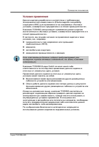
1.1 Features 1 Hardware Overview Equium A60/Satellite A60/ Pro A60/A65 Maintenance Manual 1-7 Figure 1- 3 System Board configuration CPU Expansion Memory SD/MS Card CRT PC Card Slot Speaker Left Speaker Right Head Phone Cooling Module AC Adapter MINI PCI RJ-45 RJ-11 System Board ODD INT HDD LPT Wire...
Page 22 - System Unit Components; Figure 1-4 is a block diagram of the system unit.
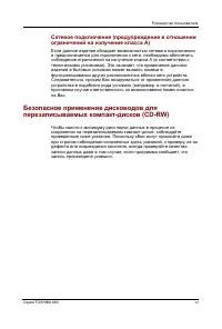
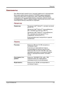
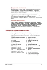
1.2 System Unit Components 1 Hardware Overview Equium A60/Satellite A60/ Pro A60/A65 Maintenance Manual 1-8 1.2 System Unit Components Figure 1-4 is a block diagram of the system unit. P C 270 0 D R A M 3 33 M H z A D M 1032 (T h erm al Se nsor) C P U : I n t e l M ob ileP 4 or Ce lero n 2 .5..,3.7 ...
Page 34 - DVD Super Multi; Table 1- 7 DVD Super Multi drive specifications
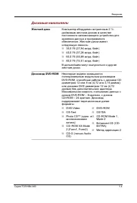
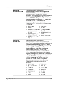
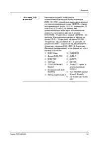
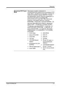
1 Hardware Overview 1.9 DVD Super Multi 1-20 Equium A60/Satellite A60/ Pro A60/A65 Maintenance Manual 1.9 DVD Super Multi The DVD Super Multi drive accepts 12-cm (4.72-inch) and 8-cm (3.15-inch) discs. At maximum, the drive can play back a DVD at 8x speed, read CD-ROM at 24x speed, and write CD-R at...
Page 36 - Main Battery; Battery Charge
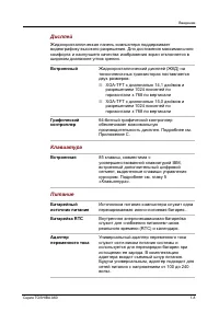
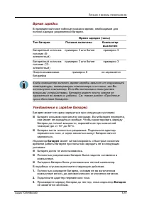
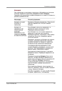
2.1 Batteries 1 Hardware Overview Equium A60/Satellite A60/ Pro A60/A65 Maintenance Manual 1-22 2.1 Batteries The computer has the following three types of batteries: ? Main battery pack ? Real time clock (RTC) battery Table 1-5 lists the specifications of these batteries. Table 1- 8 Battery specifi...
Page 37 - RTC Battery
2.1 Batteries 1 Hardware Overview Equium A60/Satellite A60/ Pro A60/A65 Maintenance Manual 1-23 NOTE: The time required for normal charge depends on the power consumption by the system. Using the fluorescent lamp and frequently accessing the disk consume much power and lengthen the charge time. Any ...
Page 38 - Troubleshooting; Chapter 2
2 Troubleshooting 2-i Equium A60/Satellite A60/ Pro A60/A65 Maintenance Manual 2 ? ? Chapter 2 Troubleshooting
Page 43 - Basic Flowchart; Make sure any piece of optional equipment has been installed.
2 Troubleshooting 2.2 Basic Flowchart 2-2 Equium A60/Satellite A60/ Pro A60/A65 Maintenance Manual 2.2 Basic Flowchart The basic flowchart in Figure 2-1 serves as a guide for identifying a possibly faulty FRU. Before going through the diagnostic flowchart steps, verify the following: ? Ask the user ...
Page 47 - Procedure 1 Power Icon Check
2 Troubleshooting 2.3 Power Supply 2-6 Equium A60/Satellite A60/ Pro A60/A65 Maintenance Manual 2.3 Power Supply The power supply in the computer controls many functions and components. To check if the power supply is defective or malfunctioning, follow the troubleshooting procedures below as instru...
Page 49 - Procedure 2 Connection Check; Power is supplied to the system board as illustrated below:; Check 1; If the DC IN LED does not go on, go to Procedure 3.; Check 3
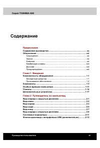
2 Troubleshooting 2.3 Power Supply 2-8 Equium A60/Satellite A60/ Pro A60/A65 Maintenance Manual Procedure 2 Connection Check Power is supplied to the system board as illustrated below: A Ca d a p t o r S y s t e m b o a r d A C p o w e r c o r d A C a d a p t o r c o r d Battery pack Follow the step...
Page 51 - Procedure 3 Replacement Check
2 Troubleshooting 2.4 System Board 2-10 Equium A60/Satellite A60/ Pro A60/A65 Maintenance Manual Procedure 2 Test Program Check The maintenance test program contains several programs for diagnosing the system board and CPU. Execute the following test programs using the procedures described in Chapte...
Page 52 - Procedure 1 Message Check
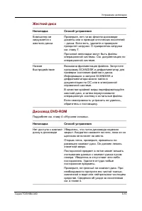
2.5 2.5-inch HDD 2 Troubleshooting Equium A60/Satellite A60/ Pro A60/A65 Maintenance Manual 2-11 2.5 2.5-inch HDD To check if the 2.5- inch HDD is defective or malfunctioning, follow the troubleshooting procedures below as instructed. Procedure 1 Message Check Procedure 2 Partition Check Procedure 3...
Page 53 - Enter; System transferred; Procedure 3 Format Check; Format complete
2 Troubleshooting 2.5 2.5-inch HDD 2-12 Equium A60/Satellite A60/ Pro A60/A65 Maintenance Manual create a DOS partition on drive C. Then restart the computer.. If the problem persists, go to Procedure 3. Check 3 If drive C is listed as active in the FDISK menu, perform Check 4. If drive C is not lis...
Page 54 - Procedure 4 Test Program Check; Table 2- 1 HDD error code and status; Code
2.5 2.5-inch HDD 2 Troubleshooting Equium A60/Satellite A60/ Pro A60/A65 Maintenance Manual 2-13 Procedure 4 Test Program Check Run the HDD test program stored on the maintenance test program disk for all test items. See Chapter 3 for details on how to use the test program. If an error is detected d...
Page 55 - Procedure 5 Connector Check and Replacement Check; H D D
2 Troubleshooting 2.5 2.5-inch HDD 2-14 Equium A60/Satellite A60/ Pro A60/A65 Maintenance Manual Procedure 5 Connector Check and Replacement Check The HDD or system board may be faulty. Disassemble the computer following the steps described in Chapter 4 and perform the following checks: Check 1 M ak...
Page 56 - Procedure 1 Test Program Check; K e y b o a r d; Check 4
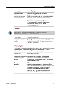
2.6 Keyboard 2 Troubleshooting Equium A60/Satellite A60/ Pro A60/A65 Maintenance Manual 2-15 2.6 Keyboard To check if the computer’s keyboard is defective or malfunctioning, follow the troubleshooting procedures below as instructed. Procedure 1 Test Program Check Procedure 2 Connector Check and Repl...
Page 57 - Procedure 1 External Monitor Check; If the FL does not light, perform Check 1.; F L; Check 2
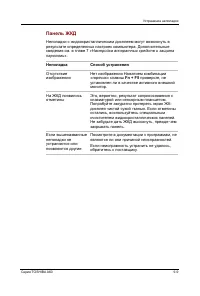
2 Troubleshooting 2.7 Display 2-16 Equium A60/Satellite A60/ Pro A60/A65 Maintenance Manual 2.7 Display To check if the computer’s display is defective or malfunctioning, follow the troubleshooting procedures below as instructed. Procedure 1 External Monitor Check Procedure 2 Test Program Check Proc...
Page 59 - Procedure 1 ODD Cleaning Check; Turn off the power to the computer.; Procedure 2 Test Program Check
2 Troubleshooting 2.8 ODD Drive 2-18 Equium A60/Satellite A60/ Pro A60/A65 Maintenance Manual 2.8 ODD (Optical Disk Drive) To check if the internal ODD drive is defective or malfunctioning, follow the troubleshooting procedures below as instructed. Procedure 1 ODD Cleaning Check Procedure 2 Test Pro...
Page 61 - Procedure 1 Test Program Check
2 Troubleshooting 2.9 LAN 2-20 Equium A60/Satellite A60/ Pro A60/A65 Maintenance Manual 2.9 LAN To check if the computer’s LAN is defective or malfunctioning, follow the troubleshooting procedures below as instructed. Procedure 1 Test Program Check Procedure 2 Connector Check and Replacement Check P...
Page 63 - Procedure 1 Test P rogram Check
2 Troubleshooting 2.11 Parallel Port 2-22 Equium A60/Satellite A60/ Pro A60/A65 Maintenance Manual 2.11 Parallel Port(Optional) To check if the computer’s Parallel Port is defective or malfunctioning, follow the troubleshooting procedures below as instructed. Procedure 1 Test Program Check Procedure...
Page 64 - Speaker
2.12 Audio Test 2 Troubleshooting Equium A60/Satellite A60/ Pro A60/A65 Maintenance Manual 2-23 2.12 Audio Test To check if the computer’s Speaker is defective or malfunctioning, follow the troubleshooting procedures below as instructed. Procedure 1 Test Program Check Procedure 2 Connector Check and...
Page 66 - Cooling Module; C o o l i n g m o d u l e
2.14 Cooling Module 2 Troubleshooting Equium A60/Satellite A60/ Pro A60/A65 Maintenance Manual 2-25 2.14 Cooling Module To check if the computer’s cooling module is defective or malfunctioning, follow the troubleshooting procedures below as instructed. Procedure 1 Test Program Check Procedure 2 Conn...
Page 68 - Diagnostic Programs; Chapter 3 Contents
3 Diagnostic Programs ii dynabook AX/Satellite AW2/Equium A60/Satellite A60/ Satellite Pro A60 A65 Maintenance Manual Chapter 3 Contents 3.1 General ...........................................................................................................................1 3.2 Quick Start .............
Page 71 - Check that all the cables are connected securely.
3.1 General 3 Diagnostic Programs dynabook AX/Satellite AW2/Equium A60/Satellite A60/ Satellite Pro A60 A65 Maintenance Manual 1 3.1 General This chapter explains the diagnostic programs which tests and diagnoses the functions of the hardware components of this computer. The diagnostic programs can ...
Page 72 - Audio Line for audio record test
3 Diagnostic Programs 3.1 General 2 dynabook AX/Satellite AW2/Equium A60/Satellite A60/ Satellite Pro A60 A65 Maintenance Manual ? A CD-ROM Driver (for CD-ROM test) ? Audio Line for audio record test ? A Data CD (for CD-ROM test) ? Loop back connector of LPT ? SD, MS Card The following chapters desc...
Page 73 - Please select a test item or select
3.2 Quick Start 3 Diagnostic Programs dynabook AX/Satellite AW2/Equium A60/Satellite A60/ Satellite Pro A60 A65 Maintenance Manual 3 3.2 Quick Start When the system is booting from Service Diagnostic CD, the following screen will be displayed: Please select a test item or select 0 to exit to MS-DOS:...
Page 74 - Space; marked in the
3 Diagnostic Programs 3.2 Quick Start 4 dynabook AX/Satellite AW2/Equium A60/Satellite A60/ Satellite Pro A60 A65 Maintenance Manual 3.2.2 Customization Test When this item is selected, the system will run the diagnostic programs according to the procedures you defined. When the test is completed, a...
Page 75 - parameter dialog window.
3.2 Quick Start 3 Diagnostic Programs dynabook AX/Satellite AW2/Equium A60/Satellite A60/ Satellite Pro A60 A65 Maintenance Manual 5 Here is another method to run the test: Highlight a test item by using arrow keys, then, press Enter to start. If there are parameters provided, user should set parame...
Page 76 - Test Result; Configuration) Then press
3 Diagnostic Programs 3.2 Quick Start 6 dynabook AX/Satellite AW2/Equium A60/Satellite A60/ Satellite Pro A60 A65 Maintenance Manual 3. Test Result System will automatically run and display the test result as follows: Following is the compar ison report of the two testing methods mentioned above: 1)...
Page 77 - The test screen would be shown as below:; END; ’. When testing the ‘; Fn; must press the ‘; ’ key at the same time.
3.2 Quick Start 3 Diagnostic Programs dynabook AX/Satellite AW2/Equium A60/Satellite A60/ Satellite Pro A60 A65 Maintenance Manual 7 3.2.3 Keyboard Layout test The test purpose is to check whether 18 kinds of European keyboards run well dur ing the test procedure. When users choose the item, the nam...
Page 79 - DMI Write
3.2 Quick Start 3 Diagnostic Programs dynabook AX/Satellite AW2/Equium A60/Satellite A60/ Satellite Pro A60 A65 Maintenance Manual 9 User can press any key to exit the program. 3.2.9 DMI Write In addition to reading the DMI information, DMI Write also permits attributes editing and updating: Manufac...
Page 80 - ESC
3 Diagnostic Programs 3.2 Quick Start 10 dynabook AX/Satellite AW2/Equium A60/Satellite A60/ Satellite Pro A60 A65 Maintenance Manual During the editing, user could press F2 to confirm the DMI attribute update or press F4 to ignore the modification. Press ESC to exit the program of DMI Write. The co...
Page 81 - to view the list and; to exit this program.
3.2 Quick Start 3 Diagnostic Programs dynabook AX/Satellite AW2/Equium A60/Satellite A60/ Satellite Pro A60 A65 Maintenance Manual 11 On the left column of the above screen, the detected hardware components are listed. The corresponding information of the detected hardware components is displayed on...
Page 82 - Select this item to exit to MS DOS.; 3 The Diagnostics Screen Explanation
3 Diagnostic Programs 3.2 Quick Start 12 dynabook AX/Satellite AW2/Equium A60/Satellite A60/ Satellite Pro A60 A65 Maintenance Manual 3.2.12 Exit to MS DOS Select this item to exit to MS DOS. 3.2.13 The Diagnostics Screen Explanation Below is an example of running a test item. It includes the follow...
Page 85 - Pause Enable; : Display ‘PAUSE’ when “Pause Enable ” is enabled; Manual Interrupt Method; : Display ‘Esc: Break’ to tell the user how to manually
3.2 Quick Start 3 Diagnostic Programs dynabook AX/Satellite AW2/Equium A60/Satellite A60/ Satellite Pro A60 A65 Maintenance Manual 15 ? Pause Enable : Display ‘PAUSE’ when “Pause Enable ” is enabled; ? Manual Interrupt Method : Display ‘Esc: Break’ to tell the user how to manually interrupt the test...
Page 86 - Options
3 Diagnostic Programs 3.3 Option 16 dynabook AX/Satellite AW2/Equium A60/Satellite A60/ Satellite Pro A60 A65 Maintenance Manual 3.3 Options 3.3.1 Overview In Service Diagnostics, with the Options menu user can configure the batch parameters, test item’s p arameters and those parameters created by t...
Page 87 - EXIT
3.3 Option 3 Diagnostic Programs dynabook AX/Satellite AW2/Equium A60/Satellite A60/ Satellite Pro A60 A65 Maintenance Manual 17 Configure batch parameters and all the test item’s parameters. ? Load Batch Parameters Upload all the test items and the parameters to the *.ini file. ? Save Batch Paramet...
Page 88 - Choose one of the following options:
3 Diagnostic Programs 3.3 Option 18 dynabook AX/Satellite AW2/Equium A60/Satellite A60/ Satellite Pro A60 A65 Maintenance Manual ? Test Order Specify the order of the test items. Choose 'Sequence' to adopt the sequential mode; choose 'Random' to run the test items in random sequence. ? Test Options ...
Page 89 - Monitor the CPU temperature.; Item’s Parameters Configuration; Repeat times of the test item.
3.3 Option 3 Diagnostic Programs dynabook AX/Satellite AW2/Equium A60/Satellite A60/ Satellite Pro A60 A65 Maintenance Manual 19 ? Monitor CPU Thermal Monitor the CPU temperature. ? Test Mode ? LOOPBOUND The chosen test items will run repeatedly according to the times specified in the 'Number of Loo...
Page 90 - Interactive; Parameters for the specific test items:
3 Diagnostic Programs 3.3 Option 20 dynabook AX/Satellite AW2/Equium A60/Satellite A60/ Satellite Pro A60 A65 Maintenance Manual ? Interactive If the item is enabled during the test, the test items that need user to response can run normally, such as PS2 Mouse test; If it is disabled, those test ite...
Page 92 - If selecting this parameter, the subtest results will be recorded.
3 Diagnostic Programs 3.3 Option 22 dynabook AX/Satellite AW2/Equium A60/Satellite A60/ Satellite Pro A60 A65 Maintenance Manual 3.3.6 LOG Parameters Setting You can access the Log Parameters screen through Service Diagnostics \Options - Generate Report. ? Report Destination If selecting 'NONE', no ...
Page 93 - Append to Old Log File; If selecting this parameter, the new log will be added to the old one.; Log Device Info on Fail; The default viewing program of Service Diagnostics is; Display LOG File
3.3 Option 3 Diagnostic Programs dynabook AX/Satellite AW2/Equium A60/Satellite A60/ Satellite Pro A60 A65 Maintenance Manual 23 If selecting this parameter, errors and time will be recorded only when the test fails. ? Append to Old Log File If selecting this parameter, the new log will be added to ...
Page 94 - Service Diagnostic Log viewer:
3 Diagnostic Programs 3.3 Option 24 dynabook AX/Satellite AW2/Equium A60/Satellite A60/ Satellite Pro A60 A65 Maintenance Manual In this screen, you can specify a Log file and view it with the viewer designated in Specify LOG Viewer. 3.3.9 LOG Viewer Service Diagnostic Log viewer: ? ?, ? Scroll a li...
Page 95 - Esc; DIAG REPORT
3.3 Option 3 Diagnostic Programs dynabook AX/Satellite AW2/Equium A60/Satellite A60/ Satellite Pro A60 A65 Maintenance Manual 25 Scroll a page backward or forward on the screen. ? Esc Exit the Log viewer. ? F1 Display the Help information about the Log viewer operations and the functional keys. ? Ct...
Page 96 - Base Memory Test : PASS
3 Diagnostic Programs 3.3 Option 26 dynabook AX/Satellite AW2/Equium A60/Satellite A60/ Satellite Pro A60 A65 Maintenance Manual Base Memory Test : PASS Extended Memory Test : PASS End Time: Mon Jan 05 10:47:51 2004 <Module Name>: Service Diagnostic Ver 1.01 ... Mouse Test Build Date 2002.12.3...
Page 97 - Chipset Fan Test
3.4 Subtests 3 Diagnostic Programs dynabook AX/Satellite AW2/Equium A60/Satellite A60/ Satellite Pro A60 A65 Maintenance Manual 27 3.4 Subtests Test Group Sub Item ID Subtest Test ID Test items Internal Name System 01 CPU 01 Basic Functionality Test [CPUBasicFun] 02 CPU Speed [CPUSpeed] 03 Coprocess...
Page 101 - CPU Speed Comparison
3.5 System Test 3 Diagnostic Programs dynabook AX/Satellite AW2/Equium A60/Satellite A60/ Satellite Pro A60 A65 Maintenance Manual 31 CPU Speed Comparison --Whether you want to make a comparison of the CPU speed with the value set in ‘Expected CPU Speed’, you should choose ‘Yes’; otherwise, ‘No’. Ex...
Page 102 - Speed Change Comparison
3 Diagnostic Programs 3.5 System Test 32 dynabook AX/Satellite AW2/Equium A60/Satellite A60/ Satellite Pro A60 A65 Maintenance Manual Speedstep is a kind of energy-saving running mode that is supported by the Pentium III or above . This test item is to check whether the CPU supports Speedstep functi...
Page 103 - Subtest 03 FAN Speed Test
3.5 System Test 3 Diagnostic Programs dynabook AX/Satellite AW2/Equium A60/Satellite A60/ Satellite Pro A60 A65 Maintenance Manual 33 This test item is to check whether the system clock/calendar works normally. 4. PCI System This test item is to check whether the bus number, device number and functi...
Page 104 - Chipset Fan Speed Test
3 Diagnostic Programs 3.5 System Test 34 dynabook AX/Satellite AW2/Equium A60/Satellite A60/ Satellite Pro A60 A65 Maintenance Manual 2. Chipset Fan Speed Test This test item is to check whether Chipset Fan exists or not. If it exists, the test will check the speed of Chipset Fan at the status of Po...
Page 105 - Subtest 01 BIOS ROM; Choose the Memory part to take the test– Base Memory or; Extended Memory Test Range:; Specify the test coverage range of
3.6 Memory Test 3 Diagnostic Programs dynabook AX/Satellite AW2/Equium A60/Satellite A60/ Satellite Pro A60 A65 Maintenance Manual 35 3.6 Memory Test This test module is to check whether the memory chip works normally. Subtest 01 BIOS ROM This test item is to check the validity of BIOS ROM that incl...
Page 106 - Extended Pattern
3 Diagnostic Programs 3.6 Memory Test 36 dynabook AX/Satellite AW2/Equium A60/Satellite A60/ Satellite Pro A60 A65 Maintenance Manual test coverage would be based on the setting and the value in ‘Percent (%) me ntioned at below. Pattern Size: Choose the pattern size – BYTE, WORD, DWORD or ALL. Perce...
Page 107 - Subtest 04 Walking 1 ’s Test
3.6 Memory Test 3 Diagnostic Programs dynabook AX/Satellite AW2/Equium A60/Satellite A60/ Satellite Pro A60 A65 Maintenance Manual 37 In addition to the above pattern test of the memory, there is Read/Write Cycle test and Read Cycle Test for the extended memory. Below is the parameter dialog window ...
Page 108 - Subtest 05 Walking 0 ’s Test; parameter dialog window is the same as that in ‘Subtest 02 Pattern’.; Subtest 06 Memory Address; parameter dialog window is as follows:; Subtest 08 Cache Memory; Randomize Test
3 Diagnostic Programs 3.6 Memory Test 38 dynabook AX/Satellite AW2/Equium A60/Satellite A60/ Satellite Pro A60 A65 Maintenance Manual The test item is to ensure that there is no short circuitry issue in memory chip. The parameter dialog window is the same as that in ‘Subtest 02 Pattern’. Subtest 05 ...
Page 109 - Subtest 10 Data Bus Test; This test item is to check whether the data bus works normally.; Subtest 11 Memory Speed Test
3.6 Memory Test 3 Diagnostic Programs dynabook AX/Satellite AW2/Equium A60/Satellite A60/ Satellite Pro A60 A65 Maintenance Manual 39 This test item is to check whether the memory could be correctly accessed with randomized memory address and a series of incremental data. Subtest 10 Data Bus Test Th...
Page 110 - Subtest 01 HDD
3 Diagnostic Programs 3.7 Storage 40 dynabook AX/Satellite AW2/Equium A60/Satellite A60/ Satellite Pro A60 A65 Maintenance Manual 3.7 Storage Subtest 01 HDD This test item runs on IDE hard disks. It checks the functions and performance of IDE hard disk. 1. Sequential/Random R/W This test item is to ...
Page 111 - Option
3.7 Storage 3 Diagnostic Programs dynabook AX/Satellite AW2/Equium A60/Satellite A60/ Satellite Pro A60 A65 Maintenance Manual 41 (1) Read & Write –Write data on the disk, then read it out and compare the two value; (2) Read Verify —Read data only; (3) Unprotected Write —Write data on the disk w...
Page 112 - Subtest 02 ODD
3 Diagnostic Programs 3.7 Storage 42 dynabook AX/Satellite AW2/Equium A60/Satellite A60/ Satellite Pro A60 A65 Maintenance Manual Check the HDD controller’s status, including HDD interrupt and unexpected interrupt. 5. Diagnostic Read/Write This test item is a quick test to verify whether the HDD cou...
Page 113 - Data CD Random Seek
3.7 Storage 3 Diagnostic Programs dynabook AX/Satellite AW2/Equium A60/Satellite A60/ Satellite Pro A60 A65 Maintenance Manual 43 Check the seek function of the ODD drive. It will perform a serial of seeking operations. F irst, locate the minimum LBA address, then the maximum, the sub -minimum, the ...
Page 114 - This test item tests the video b y:; Text Mode; Character Test
3 Diagnostic Programs 3.8 Video 44 dynabook AX/Satellite AW2/Equium A60/Satellite A60/ Satellite Pro A60 A65 Maintenance Manual 3.8 Video This test item tests the video b y: 1. displaying the figures in different graphic modes. 2. disp laying the property and color of the characters in different tex...
Page 116 - Text Color
3 Diagnostic Programs 3.8 Video 46 dynabook AX/Satellite AW2/Equium A60/Satellite A60/ Satellite Pro A60 A65 Maintenance Manual 4. Text Color This test item is to check whether all 16 colors foreground and all 8 colors background works normally in VGA text mode. The bit4-6 of the attribute byte of a...
Page 117 - VESA Video Modes
3.8 Video 3 Diagnostic Programs dynabook AX/Satellite AW2/Equium A60/Satellite A60/ Satellite Pro A60 A65 Maintenance Manual 47 In the test, user is required to respond according to the instruction in the screen. Subtest 02 640 * 480 VGA Mode This test item is to check whether 680*480 VGA Text mode ...
Page 118 - VESA Video Memory
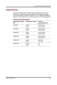
3 Diagnostic Programs 3.8 Video 48 dynabook AX/Satellite AW2/Equium A60/Satellite A60/ Satellite Pro A60 A65 Maintenance Manual 1. 640X480 Video Modes Test p 2. 800X600 Video Modes Test 3. 1024X768 Video Modes Test 4. 1280 x1024 Video Modes Test 5. 1400 X1050 Video Modes Test 6. 1600 X1200 Video Mod...
Page 119 - DDC Test
3.8 Video 3 Diagnostic Programs dynabook AX/Satellite AW2/Equium A60/Satellite A60/ Satellite Pro A60 A65 Maintenance Manual 49 Subtest 05 DDC Test This test item is to check whether the video card and the video display support DDC (Display Data Channel). Subtest 06 AGP Test This test item is to rep...
Page 120 - Register Test
3 Diagnostic Programs 3.8 Video 50 dynabook AX/Satellite AW2/Equium A60/Satellite A60/ Satellite Pro A60 A65 Maintenance Manual Subtest 08 Register Test This test item is to check whether the registers of the video adapter works normally. Subtest 09 Color Purity Test This test item is to check wheth...
Page 121 - DAC/Palette Address
3.8 Video 3 Diagnostic Programs dynabook AX/Satellite AW2/Equium A60/Satellite A60/ Satellite Pro A60 A65 Maintenance Manual 51 Subtest 11 DAC/Palette Address This test item is to check the function of DAC registers and Palette registers. In the test, user is required to respond according to the ins...
Page 122 - BitBlt Engine Test
3 Diagnostic Programs 3.8 Video 52 dynabook AX/Satellite AW2/Equium A60/Satellite A60/ Satellite Pro A60 A65 Maintenance Manual Subtest 12 BitBlt Engine Test This test item is to check whether the BitBlt engine works normally. BitBlt is the abbreviation of ‘Bit Block Translate’, that means the copy ...
Page 124 - LPT
3 Diagnostic Programs 3.9 Communication 54 dynabook AX/Satellite AW2/Equium A60/Satellite A60/ Satellite Pro A60 A65 Maintenance Manual 3.9 Communication (COMM) Subtest 01 LPT This test item is to check whether there is open or short circuit issue in the external pins by looping back the external pi...
Page 125 - IrDA
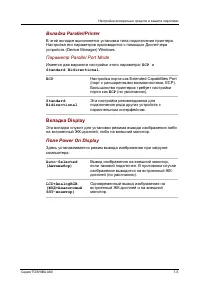
3.9 Communication 3 Diagnostic Programs dynabook AX/Satellite AW2/Equium A60/Satellite A60/ Satellite Pro A60 A65 Maintenance Manual 55 Check whether it supports ECP (Extended Capabilities Port) feature. Subtest 02 IrDA This test item is divided into Fast IR (FIR) and Slow IR (SIR). FIR supports the...
Page 126 - Below is the Master Testing window:; LAN Card; Device ID Detection
3 Diagnostic Programs 3.9 Communication 56 dynabook AX/Satellite AW2/Equium A60/Satellite A60/ Satellite Pro A60 A65 Maintenance Manual Below is the Master Testing window: Subtest 03 LAN Card This test item is to check whether the module can detect the existence of the network card and display its r...
Page 127 - Detect the vendor ID of the network card.
3.9 Communication 3 Diagnostic Programs dynabook AX/Satellite AW2/Equium A60/Satellite A60/ Satellite Pro A60 A65 Maintenance Manual 57 Detect the vendor ID of the network card. 3. MAC Address Detection Detect the MAC address of the network card. Subtest 04 1394 GUID Detection This test item is used...
Page 128 - Keyboard
3 Diagnostic Programs 3.10 Peripheral 58 dynabook AX/Satellite AW2/Equium A60/Satellite A60/ Satellite Pro A60 A65 Maintenance Manual 3.10 Peripheral Subtest 01 Keyboard This test item is to check whether the keyboard works normally. 1. Keyboard Data Line Test Check whether the keyboard data line wo...
Page 130 - Error Codes and description
3 Diagnostic Programs 3.11Error Codes and Description 60 dynabook AX/Satellite AW2/Equium A60/Satellite A60/ Satellite Pro A60 A65 Maintenance Manual 3.11 Error Codes and description The format of ‘Error Code’ is ‘ddxxee ’, and ‘dd ’ is the device ID (1~2 chars), ‘xx’ is test function ID of device (...
Page 131 - Board
3.11Error Codes and Description 3 Diagnostic Programs dynabook AX/Satellite AW2/Equium A60/Satellite A60/ Satellite Pro A60 A65 Maintenance Manual 61 02 Write-Protect Error The ROM BIOS has Physical problems. As above. 03 Base Memory Error Address The test pattern read out from the base memory is di...
Page 132 - FAN
3 Diagnostic Programs 3.11Error Codes and Description 62 dynabook AX/Satellite AW2/Equium A60/Satellite A60/ Satellite Pro A60 A65 Maintenance Manual 08 RTC Alarm Error The PC speaker's sound source ---counter/timer 8253 cannot produce corresponding timing signal. As above. 13 PCI Bus Error No PCI. ...
Page 134 - Audio
3 Diagnostic Programs 3.11Error Codes and Description 64 dynabook AX/Satellite AW2/Equium A60/Satellite A60/ Satellite Pro A60 A65 Maintenance Manual 30 32bits Video Mode Test Error As above. As above. 31xx Audio 01 Audio Play Fail Cannot play music. Check the Audio connection, replace the external ...
Page 135 - Mouse
3.11Error Codes and Description 3 Diagnostic Programs dynabook AX/Satellite AW2/Equium A60/Satellite A60/ Satellite Pro A60 A65 Maintenance Manual 65 04 Data Line Test Fail Data Line Test fails. As above. 05xx Mouse 01 Touch Pad Test Fail Touch Pad Test Fail Check the mouse connection and repeat the...
Page 137 - Quick Test Item List; Device
3.12 Quick Test Item List 3 Diagnostic Programs dynabook AX/Satellite AW2/Equium A60/Satellite A60/ Satellite Pro A60 A65 Maintena nce Manual 67 3.12 Quick Test Item List Device Test Items Comment CPU Basic Functionality NPU Basic Functions CPU Information Memory BIOS ROM Cache Memory Bit Stuck High...
Page 139 - Replacement Procedures
4 Replacement Procedures 4-ii Equium A60/ Satellite A60/ Pro A60/ A65 Maintenance Manua l
Page 140 - Chapter 4 Contents
4 Replacement Procedures Equium A60/ Satellite A60/ Pro A60/ A65 Maintenance Manua l 4-iii Chapter 4 Contents 4.1 General........................................................................................................................ 4-1 Safety Precautions.......................................
Page 145 - For removing the System Board
4.1 General 4 Replacement Procedures Equium A60/ Satellite A60/ Pro A60/ A65 Maintenance Manual 4-1 4 1 4.1 General This chapter explains how to disassemble the computer and replace Field Replaceable Units (FRUs). Some replacement procedures may not require you to remove all the surrounding FRUs to ...
Page 146 - Safety Precautions
4 Replacement Procedures 4.1 General 4-2 Equium A60/ Satellite A60/ Pro A60/ A65 Maintenance Manual Safety Precautions Before you begin disassembling, read the following safety precautions carefully. Be sure to follow them while you are working. DANGER: 1. Always use t he genuine batteries or replac...
Page 148 - Before You Begin; Disassemble the computer only when an abnormality has occurred.
4 Replacement Procedures 4.1 General 4-4 Equium A60/ Satellite A60/ Pro A60/ A65 Maintenance Manual Before You Begin Before you begin disassembling the computer, keep in mind the precautions and advice in this section. Always begin disassembling from removing the AC adapter and battery pack. Remove ...
Page 149 - Disassembly Procedures; The cable connectors come in these two basic types:; Assembly Procedures; Check that all the cable and connectors are fastened securely.
4.1 General 4 Replacement Procedures Equium A60/ Satellite A60/ Pro A60/ A65 Maintenance Manual 4-5 Disassembly Procedures The cable connectors come in these two basic types: ? Pressure plate connectors ? Normal pin connectors To remove a pressure plate connector, pull up the tabs on either side of ...
Page 150 - Tools and Equipment
4 Replacement Procedures 4.1 General 4-6 Equium A60/ Satellite A60/ Pro A60/ A65 Maintenance Manual Tools and Equipment For the safety of you and other people in the working environment, it is strongly recommended to use electrostatic discharge (ESD) equipment. The proper use of this equipment will ...
Page 151 - Colors of Screw Shanks
4.1 General 4 Replacement Procedures Equium A60/ Satellite A60/ Pro A60/ A65 Maintenance Manual 4-7 Colors of Screw Shanks For easy identification of the correct screws, the screw shanks are colored according to their lengths, as follows: ? Screws of an even-numbered length Brown ? Screws of an odd-...
Page 152 - Removing the Battery Pack; CAUTION
4 Replacement Procedures 4.1 General 4-8 Equium A60/ Satellite A60/ Pro A60/ A65 Maintenance Manual Removing the Battery Pack Remove the battery pack according to the following procedures and Figures 4-1, 4-2. CAUTION : When handling the battery packs, use care not to short circuit the terminals. Do...
Page 153 - Figure 4-2 Removing the battery pack; Installing the Battery Pack
4.1 General 4 Replacement Procedures Equium A60/ Satellite A60/ Pro A60/ A65 Maintenance Manual 4-9 B a t t e r y p a c k Figure 4-2 Removing the battery pack Installing the Battery Pack Install the battery pack according to the following procedures and Figures 4-1, 4-2. CAUTION : The battery packs ...
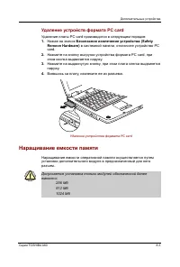
Page 154 - Removing the Optional PC Card; Figure 4-3 Removing the PC card
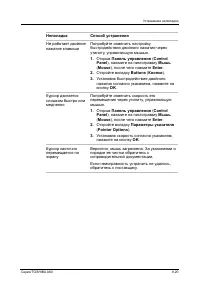
4 Replacement Procedures 4.1 General 4-10 Equium A60/ Satellite A60/ Pro A60/ A65 Maintenance Manual Removing the Optional PC Card Remove the optional PC card according to the following procedures and Figure 4-3, after checking that computer is turned off in boot mode. CAUTION : Install or remove th...
Page 155 - Installing the Optional PC Card; Insert the PC card gently until it stops and is seated securely.
4.1 General 4 Replacement Procedures Equium A60/ Satellite A60/ Pro A60/ A65 Maintenance Manual 4-11 Installing the Optional PC Card Install the optional PC card according to the following procedures and Figure 4-3, after checking that the computer is turned off in boot mode. 1. Insert the PC card g...
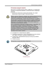
Page 156 - Removing the Optional Memory; Figure 4-4 Removing the memory cover
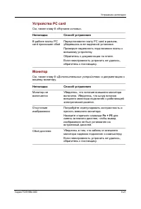
4 Replacement Procedures 4.1 General 4-12 Equium A60/ Satellite A60/ Pro A60/ A65 Maintenance Manual Removing the Optional Memory Remove the optional memory (module) according to the following procedures and Figures 4-4 and 4-5, after checking that the computer is turned off in boot mode. CAUTION : ...
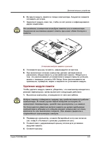
Page 157 - Figure 4-5 Removing the optional memory
4.1 General 4 Replacement Procedures Equium A60/ Satellite A60/ Pro A60/ A65 Maintenance Manual 4-13 4. Spread out the two memory lock stoppers so that the memory module can be raised. 5. Pull the memory module up and out at an angle, using care to the connectors. Menory S l o t S t o p e r Memory F...
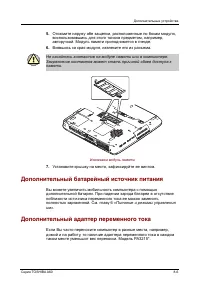
Page 158 - Installing the Optional Memory
4 Replacement Procedures 4.1 General 4-14 Equium A60/ Satellite A60/ Pro A60/ A65 Maintenance Manual Installing the Optional Memory Install the optional memory (module) according to the following procedures and Figures 4-4 and 4-5, after checking that the computer is turned off in boot mode. CAUTION...
Page 159 - Removing the MDC Card; Figure 4-6 Removing the MDC cover
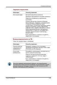
4.1 General 4 Replacement Procedures Equium A60/ Satellite A60/ Pro A60/ A65 Maintenance Manual 4-15 Removing the MDC Card Remove the MDC Card (Modem Daughter Card) according to the following procedures and Figures 4-6 and 4-7, after checking that the computer is turned off in boot mode. CAUTION : R...
Page 160 - Remove the two M2x3 white bind screws for securing the MDC card.; Figure 4-7 Removing the MDC card
4 Replacement Procedures 4.1 General 4-16 Equium A60/ Satellite A60/ Pro A60/ A65 Maintenance Manual 4. Remove the two M2x3 white bind screws for securing the MDC card. 5. Raise the MDC card and disconnect it from CN502 on the system board. 6. Disconnect the MDC cable from the connector JP1 on the M...
Page 161 - Installing the MDC Card
4.1 General 4 Replacement Procedures Equium A60/ Satellite A60/ Pro A60/ A65 Maintenance Manual 4-17 Installing the MDC Card Install the MDC card according to the following procedures and Figures 4-6 and 4-7, after checking that the computer is turned off in boot mode. CAUTION : Install the MDC card...
Page 162 - Wireless LAN Card; Removing the Wireless LAN Card; Figure 4-8 Removing the wireless LAN card cover
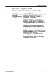
4 Replacement Procedures 4.2 Wireless LAN Card 4-18 Equium A60/ Satellite A60/ Pro A60/ A65 Maintenance Manual 4.2 Wireless LAN Card Removing the Wireless LAN Card Remove the wireless LAN card according to the following procedures and Figures 4-8 and 4-9. CAUTION : Do not touch the connectors on the...
Page 163 - Black wire; Figure 4-9 Removing the wireless LAN card; Installing the Wireless LAN Card; Connect the two antenna cables with the tweezers.
4.2 Wireless LAN Card 4 Replacement Procedures Equium A60/ Satellite A60/ Pro A60/ A65 Maintenance Manual 4-19 Black wire White wire A n t e n n a c a b l e S t o p p e r W i r e l e s s L A N c a r d Figure 4-9 Removing the wireless LAN card Installing the Wireless LAN Card Install the wireless LAN...
Page 164 - Removing the HDD; Figure 4-10 Removing the HDD pack cover
4 Replacement Procedures 4.3 HDD 4-20 Equium A60/ Satellite A60/ Pro A60/ A65 Maintenance Manual 4.3 HDD Removing the HDD CAUTION : Do not press the top or bottom of the drive. Applying such pressure can corrupt the data in the drive or damage the drive. Remove the HDD (hard disk drive) according to...
Page 165 - Figure 4-11 Removing the HDD pack; Figure 4-12 Removing the HDD chassis
4.3 HDD 4 Replacement Procedures Equium A60/ Satellite A60/ Pro A60/ A65 Maintenance Manual 4-21 H D D p a c k Figure 4-11 Removing the HDD pack 4. Remove the HDD pack by pulling the HDD tap attached to the HDD pack. NOTE: Do not disassemble the HDD pack when it is working normally. Disassemble or r...
Page 166 - Installing the HDD
4 Replacement Procedures 4.3 HDD 4-22 Equium A60/ Satellite A60/ Pro A60/ A65 Maintenance Manual Installing the HDD Install the HDD according to the following procedures and Figures 4-10, 4-11 and 4-12. CAUTION : To avoid damage, always hold the HDD only by its sides. 1. Secure the HDD and its brack...
Page 167 - Switch Cover and Hotkey Board; Removing the Switcher; Open the display panel.; Figure 4-13 Removing the switch cover screw
4.4 Switch Cover and Hotkey board 4 Replacement Procedures Equium A60/ Satellite A60/ Pro A60/ A65 Maintenance Manual 4-23 4.4 Switch Cover and Hotkey Board Removing the Switcher Remove the switch cover and hotkey board according to the following procedures and Figures 4-13, 4-14. 1. Open the displa...
Page 168 - Figure 4-14 Removing the hotkey board; Installing the Switch Cover and Hotkey Board; Connect the SUMI-card to CN2000 on the hotkey board.
4 Replacement Procedures 4.4 Switch Cover and Hotkey board 4-24 Equium A60/ Satellite A60/ Pro A60/ A65 Maintenance Manual M2.5x4 black flat-head screw Hotkey board C N 2 0 0 1 S U M I - c a r d Figure 4-14 Removing the hotkey board Installing the Switch Cover and Hotkey Board Install the switch cov...
Page 169 - Removing the Keyboard; Figure 4-15 Removing the keyboard
4.5 Keyboard 4 Replacement Procedures Equium A60/ Satellite A60/ Pro A60/ A65 Maintenance Manual 4-25 4 1 4.5 Keyboard Removing the Keyboard Remove the keyboard according to the following procedures and Figures 4-15. 1. Remove two M2.5x2.6 black bind screws. Figure 4-15 Removing the keyboard 2. Move...
Page 170 - Installing the Keyboard; Connect the keyboard cable to CN16 on the system board.
4 Replacement Procedures 4.5 Keyboard 4-26 Equium A60/ Satellite A60/ Pro A60/ A65 Maintenance Manual Installing the Keyboard Install the keyboard according to the following procedures and Figures 4-15. 1. Connect the keyboard cable to CN16 on the system board. 2. Align the latches on the rear of th...
Page 171 - ODD Bay Modules; Removing the ODD Bay Module; Turn the computer upside down.; Figure 4-16 Removing the ODD bay module
4.6 ODD Bay Module 4 Replacement Procedures Equium A60/ Satellite A60/ Pro A60/ A65 Maintenance Manual 4-27 4.6 ODD Bay Modules Removing the ODD Bay Module NOTE: The installation and removal procedures are the same for all the modules that can be installed in the ODD bays. See the appropriate sectio...
Page 172 - Installing the ODD Bay Module; Place the ODD bay module in the correct position and slide it in.
4 Replacement Procedures 4.6 ODD Bay Module 4-28 Equium A60/ Satellite A60/ Pro A60/ A65 Maintenance Manual Push here ODD bay module Figure 4-16 Removing the ODD bay module Installing the ODD Bay Module Install the ODD bay module according to the following procedures and Figure 4-16, 4-17. 1. Place ...
Page 173 - Disassembling the ODD Drive; replace the ODD drive only if it failed.; Assembling the ODD Drive; Secure the bracket with the two M2x3 white flat-head screws.
4.6 ODD Bay Module 4 Replacement Procedures Equium A60/ Satellite A60/ Pro A60/ A65 Maintenance Manual 4-29 Disassembling the ODD Drive NOTE: Do not disassemble the ODD drive when it is working normally. Disassemble or replace the ODD drive only if it failed. Disassemble the ODD drive according to t...
Page 174 - Display Assembly; Removing the Display Assembly
4 Replacement Procedures 4.7 Display Assembly 4-30 Equium A60/ Satellite A60/ Pro A60/ A65 Maintenance Manual 4.7 Display Assembly Removing the Display Assembly CAUTION : Use care to avoid that the antenna cable for antenna is caught between the display assembly and computer. Remove the display asse...
Page 175 - Installing the Display Assembly; Securing display assembly with four M2.5x5 black flat-head screws.
4.7 Display Assembly 4 Replacement Procedures Equium A60/ Satellite A60/ Pro A60/ A65 Maintenance Manual 4-31 Figure 4-20 Removing the display assembly Installing the Display Assembly Install the display assembly according to the following procedures and Figures 4-19, 4-20. 1. Place the display pane...
Page 176 - Removing the Top Cover; Figure 4-21 Removing the screws from the bottom of the computer
4 Replacement Procedures 4.8 Top Cover 4-32 Equium A60/ Satellite A60/ Pro A60/ A65 Maintenance Manual 4.8 Top Cover Removing the Top Cover Remove the top cover according to the following procedures and Figures 4-21 and 4-22. 1. Turn the computer upside down, and remove the following 25 screws: - Tw...
Page 177 - Figure 4-22 Removing the top cover
4.8 Top Cover 4 Replacement Procedures Equium A60/ Satellite A60/ Pro A60/ A65 Maintenance Manual 4-33 C N 2 3 C N 1 7 LID switch cable L E D S U M I - c a r d T o p c o v e r Figure 4-22 Removing the top cover 3. Disconnect the LED board flat cable from CN17. 4. Lift up the top cover. 5. Disconnect...
Page 178 - Installing the Top cover; Connect the lid switch flat cables to CN23 on the system board.
4 Replacement Procedures 4.8 Top Cover 4-34 Equium A60/ Satellite A60/ Pro A60/ A65 Maintenance Manual Installing the Top cover Install the top cover with the display assembly according to the following procedures and Figures 4-21, 4-22. 1. Connect the lid switch flat cables to CN23 on the system bo...
Page 179 - Removing the Speakers; Remove the speaker cables fix tape.; Figure 4-23 Removing the speakers
4.9 Speakers 4 Replacement Procedures Equium A60/ Satellite A60/ Pro A60/ A65 Maintenance Manual 4-35 4.9 Speakers Removing the Speakers Remove the speakers according to the following procedures and Figure 4-23. 1. Remove the speaker cables fix tape. 2. Remove the speaker cables from the guides (gro...
Page 180 - Installing th e Speakers; Connect the speaker cables to CN20 on the system board.
4 Replacement Procedures 4.9 Speakers 4-36 Equium A60/ Satellite A60/ Pro A60/ A65 Maintenance Manual Installing th e Speakers Install the speakers according to the following procedures and Figure 4-23. 1. Connect the speaker cables to CN20 on the system board. 2. Place the left and right speakers i...
Page 181 - Replacement Procedures; Cooling Module; When removing the cooling module, keep the following in mind:; Removing the Cooling Module; Release the one screw next to the fan.; Figure 4-24 Removing the cooling module
4.10 Cooling Module 4 Replacement Procedures Equium A60/ Satellite A60/ Pro A60/ A65 Maintenance Manual 4 - 37 4.10 Cooling Module CAUTION: When removing the cooling module, keep the following in mind: 1. The cooling module can become very hot during operation. Be sure to let it cool down before sta...
Page 182 - Installing the Cooling Module; When installing the cooling module, keep the following in mind:
4 Replacement Procedures 4.10 Cooling Module 4-38 Equium A60/ Satellite A60/ Pro A60/ A65 Maintenance Manual Installing the Cooling Module Install the cooling module according to the following procedures and Figures 4-24, 4-25. CAUTION: When installing the cooling module, keep the following in mind:...
Page 184 - CPU; When removing the CPU, keep the following in mind:; Removing the CPU; Remove the CPU by aligning the triangle with the shaded area.
4 Replacement Procedures 4.11 CPU 4-40 Equium A60/ Satellite A60/ Pro A60/ A65 Maintenance Manual 4.11 CPU CAUTION: When removing the CPU, keep the following in mind: The CPU can become very hot during operation. Be sure to let it cool down before starting repair work. Removing the CPU Remove the CP...
Page 185 - Installing the CPU; Check that the triangle on the cam is in the unlocking position.; Figure 4-27 Installing the CPU
4.11 CPU 4 Replacement Procedures Equium A60/ Satellite A60/ Pro A60/ A65 Maintenance Manual 4 - 41 Installing the CPU Install the CPU according to the following procedures and Figures 4-26, 4-27 and 4-28. 1. Check that the triangle on the cam is in the unlocking position. 2. Attach the CPU to the c...
Page 187 - Remove the M2.5x5 black flat-head screws for securing the HDD tray.
4.12 System Board 4 Replacement Procedures Equium A60/ Satellite A60/ Pro A60/ A65 Maintenance Manual 4 - 43 4.12 System Board Removing the System Board NOTE: Be careful of the eject button for the PC card. It can be damage when removing the board. Make sure it is pushed in. Remove the system board ...
Page 188 - Installing the System Board; Place the slider for the kill switch on the system board.
4 Replacement Procedures 4.12 System Board 4-44 Equium A60/ Satellite A60/ Pro A60/ A65 Maintenance Manual Installing the System Board Install the touch pad according to the following procedures and figure 4-29. 1. Place the slider for the kill switch on the system board. 2. Seat the system board an...
Page 189 - North Bridge thermal module and MDC cable; Turn the system board upside down.
4.13 North Bridge Thermal Module 4 Replacement Procedures Equium A60/ Satellite A60/ Pro A60/ A65 Maintenance Manual 4 - 45 4.13 North Bridge thermal module and MDC cable Removing North Bridge thermal module and MDC cable Remove the North Bridge thermal module according to the following procedures a...
Page 192 - Display Mask; Figure 4-32 Removing the display mask
4 Replacement Procedures 4.14 Display Mask 4-48 Equium A60/ Satellite A60/ Pro A60/ A65 Maintenance Manual 4.14 Display Mask Removing the Display Mask Remove the display mask according to the following procedures and Figure 4-32. 1. Remove the following 8 seals on the display module in that order: -...
Page 193 - Installing the Display Mask
4.14 Display Mask 4 Replacement Procedures Equium A60/ Satellite A60/ Pro A60/ A65 Maintenance Manual 4 - 49 Installing the Display Mask Install the display mask according to the following procedures and Figure 4-32. 1. Place the display mask in the correct position and fasten the following 18 latch...
Page 194 - FL Inverter Board; Figure 4-33 Removing the FL inverter board
4 Replacement Procedures 4.15 FL Inverter Board 4-50 Equium A60/ Satellite A60/ Pro A60/ A65 Maintenance Manual 4.15 FL Inverter Board Removing the FL Inverter Board Remove the FL inverter board according to the following procedures and Figures 4-33 and 4-34. 1. Remove the M2.5x4.5 black flat-head s...
Page 195 - Figure 4-34 disconnecting the cables; Installing the FL Inverter Board; Place the FL inverter board in the correct position.
4.15 FL Inverter Board 4 Replacement Procedures Equium A60/ Satellite A60/ Pro A60/ A65 Maintenance Manual 4 - 51 F L i n v e r t e r b o a r d L C D / F L c a b l e H V c a b l e Figure 4-34 disconnecting the cables Installing the FL Inverter Board Install the FL inverter board according to the fol...
Page 196 - LCD Modules; edges of the LCD module.
4 Replacement Procedures 4.16 LCD Module 4-52 Equium A60/ Satellite A60/ Pro A60/ A65 Maintenance Manual 4.16 LCD Modules NOTE: ICs are fragile. Use extreme care not to apply pressure to the ICs along the edges of the LCD module. NOTE: Dispose of used LCD panels (fluorescent (FL) tubes) as required ...
Page 197 - Replacement Procedure
4.16 LCD Module 4 Replacement Procedure s Equium A60/ Satellite A60/ Pro A60/ A65 Maintenance Manual 4 - 53 M2x5 white bind screw M2.5x4.5 black flat-head screw Figure 4-35 Removing the 15.0-inch LCD module and screws
Page 203 - LED Board; Remove the ESD tape for fix LED flat cable.; Figure 4-41 Removing the LED board
4.17 LED board 4 Replacement Procedures Equium A60/ Satellite A60/ Pro A60/ A65 Maintenance Manual 4 - 59 4.17 LED Board Removing the LED Board Remove the LED board according to the following procedures and Figure 4-41. NOTE: Be carefully peel away the 3 tapes securing the board bef ore you can remo...
Page 204 - Installing the LED Board; Connect the touch pad flat cables to J1 on the touch pad.
4 Replacement Procedures 4.17 LED Board 4-60 Equium A60/ Satellite A60/ Pro A60/ A65 Maintenance Manual Installing the LED Board Install the LED board according to the following procedures and Figure 4-41. 1. Connect the touch pad flat cables to CN2000 and LED board flat cable to CN2002 on the LED b...
Page 205 - Touch Pad Board; Remove the Touch Pad Board.; Figure 4-42 Removing the touch pad board; Installing the Touch Pad Board; Place the touch pad board in the correct position.
4.18 Touch Pad Board 4 Replacement Procedure s Equium A60/ Satellite A60/ Pro A60/ A65 Maintenance Manual 4 - 61 4.18 Touch Pad Board Removing the Touch Pad Board Remove the s Touch Pad Board according to the following procedures and Figure 4-42. 1. Remove the two M2.5x4 black flat-head screws for s...
Page 208 - Appendix; Appendix A Handling the LCD Module
Appendices Equium A60/Satellite A60/ Pro A60/A65 Maintenance Manual App-iii Appendix Contents Appendix A Handling the LCD Module .............................................................................. A-1 Appendix B Board Layout ...................................................................
Page 209 - Appendix D Keyboard Scan/Character Codes
Appendices App-iv Equium A60/Satellite A60/ Pro A60/A65 Maintenance Manual C.21 CN2002 LED Connector (24-Pin) ........................................................................ C-16 C.22 JACK1 DC_IN Connector (2-Pin)........................................................................ C-17 ...
Page 210 - Tables
Appendices Equium A60/Satellite A60/ Pro A60/A65 Maintenance Manual App-v Figures Figure B-1 Board layout (front) ..............................................................................................B-1 Figure B-2 Board layout (back).............................................................
Page 212 - Precautions for handling the LCD module
Apx. A Handling the LCD Module Appendices Equium A60/ Satellite A60/ Pro A60/A65 Maintenance Manual A-1 Appendix A Appendix A Handling the LCD Module Precautions for handling the LCD module The LCD module can be easily damaged during assembly or disassembly. Observe the following precautions when ha...
Page 217 - Appendix B Board Layout
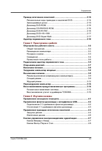
Apx. B Board Layout Appendices Equium A60/ Satellite A60/ Pro A60/A65 Maintenance Manual B-1 Appendix B Appendix B Board Layout B.1 System Board Front View Figure B-1 Board layout (front) \_ A B C D E F G H I J K L M N O P Q R S T
Page 218 - FAN 1
Appendices Apx. B Board Layout B-2 Equium A60/ Satellite A60/ Pro A60/A65 Maintenance Manual Table B-1 System board connectors (front) Mark Number Name A’ CN13 LCD/FL Inverter Connector B’ CN12 ODD Bay Connector C’ CN9 SD/MS Connector D’ CN4 IEEE 1394 Connector E’ CN1 Parallel Connector F’ CN2 Exter...
Page 220 - MINI PCI Connector
Appendices Apx. B Board Layout B-4 Equium A60/ Satellite A60/ Pro A60/A65 Maintenance Manual Table B-2 System board ICs and connectors (back ) Mark Number Name A’ CN501 MINI PCI Connector B’ CN502 MDC Connector C’ CN504 Serial Connector D’ CN503 Memory Slot A Connector
Page 222 - Appendix C Pin Assignments
Appendices Apx. C Pin Assignments C-2 Equium A60/ Satellite A60/ Pro A60/A65 Maintenance Manual Appendix C Appendix C Pin Assignments System Board C.1 CN1 Parallel Connector (25-Pin) Table C-1 Parallel connector pin assignments (25-PIN) Pin No. Signal Name I/O Pin No. Signal Name I/O 1 /STRB#_5R O 2...
Page 241 - * Scan codes differ by overlay function.; key makes different codes.; key does not generate a code by itself.
Appendices Keyboard Scan/Character Codes D-4 Equium A60/Satellite A60/ Pro A60/A65 Maintenance Manual Table D-1 Scan codes (set 1 and set 2) (4/4) Cap Code set 1 Code set 2 No. Keytop Make Break Make Break Note 122 F11 57 D7 78 F0 78 *3 123 F12 58 D8 7 F0 7 *3 124 PrintSc *6 *6 *6 *6 *6 126 Pause *7...
Page 242 - Shift
Keyboard Scan/Character Codes Appendices Equium A60/Satellite A60/ Pro A60/A65 Maintenance Manual D-5 Table D-2 Scan codes with left Shift key Code set 1 Code set 2 Cap No. Key top Make Break Make Break 55 / E0 AA E0 35 E0 B5 E0 2A E0 F0 12 E0 4A E0 F0 4A E0 12 75 INS E0 AA E0 52 E0 D2 E0 2A E0 F0 1...
Page 243 - Table D-3 Scan codes in Numlock mode
Appendices Keyboard Scan/Character Codes D-6 Equium A60/Satellite A60/ Pro A60/A65 Maintenance Manual Table D-3 Scan codes in Numlock mode Code set 1 Code set 2 Cap No. Key top Make Break Make Break 75 INS E0 2A E0 52 E0 D2 E0 AA E0 12 E0 70 E0 F0 70 E0 F0 12 76 DEL E0 2A E0 53 E0 D3 E0 AA E0 12 E0 ...
Page 246 - Appendix E Key Layout; Figure E-1 US keyboard
Apx. E Key Layout Appendices Equium A60/Satellite A60/ Pro A60/A65 Maintenance Manual E-1 Apx. E K e y L a y o u t Appendix E Key Layout E.1 United States (US) Keyboard Figure E-1 US keyboard E.2 Japan (JP) Keyboard Figure E-2 JP keyboard
Page 260 - Appendix F BIOS Rewrite Procedures; Tools; To rewrite the BIOS, you need the following tool:; Rewriting the BIOS; Set the system to boot mode.
Apx. F BIOS Rewrite Procedures Appendices Equium A60/ Satellite A60/ Pro A60/A65 Maintenance Manual F-1 Appendix G Appendix F BIOS Rewrite Procedures This Appendix explains how to rewrite the system BIOS program when you update the system BIOS. Tools To rewrite the BIOS, you need the following tool:...
Page 261 - Appendix G EC/KBC Rewrite Procedures
Apx. G EC/KBC Rewrite Procedures Appendices Equium A60/ Satellite A60/ Pro A60/A65 Maintenance Manual G-1 Appendix H Appendix G EC/KBC Rewrite Procedures This Appendix explains how to rewrite the EC/KBC system program when you update the EC/KBC system. Tools To rewrite the EC/KBC, you need the follo...


 Toshiba Portege Z830
User Manual
Toshiba Portege Z830
User Manual
 Toshiba Qosmio G30
User Manual
Toshiba Qosmio G30
User Manual
 Toshiba Qosmio X300
User Manual
Toshiba Qosmio X300
User Manual
 Toshiba Satellite 5200
User Manual
Toshiba Satellite 5200
User Manual
 Toshiba Satellite A10
User Manual
Toshiba Satellite A10
User Manual
 Toshiba Satellite A100
User Manual
Toshiba Satellite A100
User Manual
 Toshiba Satellite A20
User Manual
Toshiba Satellite A20
User Manual
 Toshiba Satellite A200
User Manual
Toshiba Satellite A200
User Manual
 Toshiba Satellite A210
User Manual
Toshiba Satellite A210
User Manual
 Toshiba Satellite A40
User Manual
Toshiba Satellite A40
User Manual
 Toshiba Satellite A50
User Manual
Toshiba Satellite A50
User Manual
 Toshiba Satellite C670 (D)
User Manual
Toshiba Satellite C670 (D)
User Manual
 Toshiba Satellite L100
User Manual
Toshiba Satellite L100
User Manual
 Toshiba Satellite L20
User Manual
Toshiba Satellite L20
User Manual
 Toshiba Satellite L30
User Manual
Toshiba Satellite L30
User Manual
 Toshiba Satellite L40
User Manual
Toshiba Satellite L40
User Manual
 Toshiba Satellite L775 (D)
User Manual
Toshiba Satellite L775 (D)
User Manual
 Toshiba Satellite M100
User Manual
Toshiba Satellite M100
User Manual