Page 3 - iii; Preface; configuration, refer to the parts list dedicated to it.; SAFETY PRECAUTIONS; serious bodily injury, if the safety instruction is not observed.
QOSMIO G30 Maintenance Manual (960-546) [CONFIDENTIAL] iii Preface This maintenance manual describes how to perform hardware service maintenance for the Toshiba Personal Computer QOSMIO G30. NOTE: Each model of QOSMIO G30 has a different configuration. For each model’s configuration, refer to the pa...
Page 4 - iv
iv [CONFIDENTIAL] QOSMIO G30 Maintenance Manual (960-546) The manual is divided into the following parts: Chapter 1 Hardware Overview describes the QOSMIO G30 system unit and each FRU. Chapter 2 Troubleshooting Procedures explains how to diagnose and resolve FRU problems. Chapter 3 Test and Diagnost...
Page 5 - Conventions; Acronyms; boldface; Key operation; Ctrl; and at the same time press
QOSMIO G30 Maintenance Manual (960-546) [CONFIDENTIAL] v Conventions This manual uses the following formats to describe, identify, and highlight terms and operating procedures. Acronyms On the first appearance and whenever necessary for clarification acronyms are enclosed in parentheses following th...
Page 6 - vi; Table of Contents; Chapter 1
vi [CONFIDENTIAL] QOSMIO G30 Maintenance Manual (960-546) Table of Contents Chapter 1 Hardware Overview 1.1 Features ...................................................................................................................... 1-1 1.2 System Block Diagram ......................................
Page 7 - vii; Chapter 3; ONE
QOSMIO G30 Maintenance Manual (960-546) [CONFIDENTIAL] vii 2.17 Bridge media Slot Troubleshooting ......................................................................... 2-69 2.18 PCI ExpressCard Slot Troubleshooting ................................................................... 2-70 2.19 Fin...
Page 8 - viii; Chapter 4; sensor
viii [CONFIDENTIAL] QOSMIO G30 Maintenance Manual (960-546) 3.28 Wireless LAN Test Program (Intel-made a/b/g)...................................................... 3-69 3.29 LAN/Modem/Bluetooth/IEEE1394 Test Program .................................................. 3-74 3.30 Sound Test program .......
Page 9 - ix; Appendices
QOSMIO G30 Maintenance Manual (960-546) [CONFIDENTIAL] ix 4.27 GPU heat sink .......................................................................................................... 4-63 4.28 Analog TV tuner .............................................................................................
Page 12 - Hardware Overview
1 Hardware Overview 1-ii [CONFIDENTIAL] QOSMIO G30 Maintenance Manual (960-546) 1 Hardware Overview
Page 13 - Inverter
1 Hardware Overview QOSMIO G30 Maintenance Manual (960-546) [CONFIDENTIAL] 1-iii Chapter 1 Contents 1.1 Features ...................................................................................................................... 1-1 1.2 System Block Diagram ..........................................
Page 14 - Figures
1 Hardware Overview 1-iv [CONFIDENTIAL] QOSMIO G30 Maintenance Manual (960-546) Figures Figure 1-1 Front of the computer and the system units configuration ............................ 1-5 Figure 1-2 System block diagram ..................................................................................
Page 20 - Block; Figure 1-2 shows the system block diagram.
1 Hardware Overview 1.2 System Block Diagram 1.2 System Block Diagram Figure 1-2 shows the system block diagram. Figure 1-2 System block diagram 1-6 [CONFIDENTIAL] QOSMIO G30 Maintenance Manual (960-546)
Page 25 - Data transfer rate
1.3 2.5-inch Hard Disk Drive 1 Hardware Overview QOSMIO G30 Maintenance Manual (960-546) [CONFIDENTIAL] 1-11 Table 1-2 2.5-inch HDD Specifications Specification Parameter FUJITSU G8BC00028410 FUJITSU G8BC00028610 FUJITSU G8BC00028810 FUJITSU G8BC00028A10 Storage size (formatted) 40GB 60GB 80GB 100GB...
Page 26 - Drive; Parameter Standard; Maker
1 Hardware Overview 1.4 Optical Drive 1.4 Optical Drive 1.4.1 DVD Super Multi Drive (supporting Double-Layer) The DVD Super Multi drive (supporting Double Layer) accommodates 12 cm (4.72-inch) CD/DVD-ROM, CD-R/RW, DVD±R/±RW and DVD-RAM. It is a high-performance drive that reads DVD-ROM at maximum 8-...
Page 27 - Drive Specification
1.4 Optical Drive 1 Hardware Overview QOSMIO G30 Maintenance Manual (960-546) [CONFIDENTIAL] 1-13 Table 1-4 DVD Super Multi drive (Double-Layer) specifications Drive Specification Parameter MATSUSHITA (G8CC0002PZ20) Read DVD-ROM MAX 8x CAV CD-ROM MAX 24x CAV Write (Maximum) CD-R 24x (ZoneCLV) CD-RW ...
Page 31 - TFT Color Display; Module; Figure 1-7 LCD module; Number of Dots; Number of Dots
1.6 TFT Color Display 1 Hardware Overview 1.6 TFT Color Display The TFT color display is 17.1 inch and consists of LCD module and FL inverter board. 1.6.1 LCD Module The LCD module used for the TFT color display uses a backlight as the light source and can display a maximum of 320,000 colors with 1,...
Page 32 - Input
1 Hardware Overview 1.6 TFT Color Display 1-18 [CONFIDENTIAL] QOSMIO G30 Maintenance Manual (960-546) 1.6.2 FL Inverter Board The FL inverter board supplies a high frequency current to illuminate the LCD module FL. Table 1-8 lists the FL inverter board specifications. Table 1-8 FL inverter board spe...
Page 33 - Supply
1.7 Power Supply 1 Hardware Overview QOSMIO G30 Maintenance Manual (960-546) [CONFIDENTIAL] 1-19 1.7 Power Supply The power supply supplies 34 different voltages to the system board. The power supply microcontroller has the following functions. 1. Judges if the DC power supply (AC adapter) is connec...
Page 34 - Name
1 Hardware Overview 1.7 Power Supply 1-20 [CONFIDENTIAL] QOSMIO G30 Maintenance Manual (960-546) Table 1-9 Power supply output rating (1/2) Power supply ( Yes/No ) Name Voltage [V] Power OFF (Suspend mode) Power OFF (Boot mode) No Battery Object PPV 1.500 - 0.300 No No No CPU PTV 1.05 No No No CPU, ...
Page 36 - Battery Name; Lithium ion 6 cell; Battery
1 Hardware Overview 1.8 Batteries 1-22 [CONFIDENTIAL] QOSMIO G30 Maintenance Manual (960-546) 1.8 Batteries The PC has the following two batteries. Main battery Real time clock (RTC) battery Table 1-10 lists the specifications for these two batteries. Table 1-10 Battery specifications Battery Na...
Page 37 - Battery type; Table 1-12 Data preservation time; Condition preservation; Standby
1.8 Batteries 1 Hardware Overview QOSMIO G30 Maintenance Manual (960-546) [CONFIDENTIAL] 1-23 1.8.2 Battery Charging Control Battery charging is controlled by a power supply microprocessor. The power supply microprocessor controls power supply and detects a full charge when the AC adaptor and batter...
Page 38 - Table 1-13 Time required for charges of RTC battery; Condition Time; About 8 hours
1 Hardware Overview 1.8 Batteries 1-24 [CONFIDENTIAL] QOSMIO G30 Maintenance Manual (960-546) 1.8.3 RTC Battery The RTC battery provides the power supply to maintain the date, time, and other system information in memory. Table 1-13 lists the Time required for charges of RTC battery and data preserv...
Page 39 - Adapter; The AC adapter is used to charge the battery.; Specification
1.9 AC Adapter 1 Hardware Overview QOSMIO G30 Maintenance Manual (960-546) [CONFIDENTIAL] 1-25 1.9 AC Adapter The AC adapter is used to charge the battery. Table 1-14 lists the AC adapter specifications. Table 1-14 AC adapter specifications Parameter Specification G71C0002R710/ G71C0002R810 (2-pin) ...
Page 42 - Troubleshooting Procedures
2 Troubleshooting Procedures 2-ii [CONFIDENTIAL] QOSMIO G30 Maintenance Manual (960-546) 2
Page 43 - Chapter 2
2 Troubleshooting Procedures QOSMIO G30 Maintenance Manual (960-546) [CONFIDENTIAL] 2-iii Chapter 2 Contents 2.1 Troubleshooting ......................................................................................................... 2-1 2.2 Troubleshooting Flowchart ..................................
Page 49 - Flowchart; Ask him or her to enter the password if a password is registered.
2.2 Troubleshooting Flowchart 2 Troubleshooting Procedures QOSMIO G30 Maintenance Manual (960-546) [CONFIDENTIAL] 2-3 2.2 Troubleshooting Flowchart Use the flowchart in Figure 2-1 as a guide for determining which troubleshooting procedures to execute. Before going through the flowchart steps, verify...
Page 54 - Procedure 1; Table 2-1 Battery icon; Battery icon; Lights orange
2 Troubleshooting Procedures 2.3 Power Supply Troubleshooting 2-8 [CONFIDENTIAL] QOSMIO G30 Maintenance Manual (960-546) 2.3 Power Supply Troubleshooting The power supply controller controls many functions and components. To determine if the power supply is functioning properly, start with Procedure...
Page 55 - DC IN icon; When the icon is blinking, perform the following procedure.
2.3 Power Supply Troubleshooting 2 Troubleshooting Procedures QOSMIO G30 Maintenance Manual (960-546) [CONFIDENTIAL] 2-9 Table 2-2 DC IN icon DC IN icon Power supply status Lights blue DC power is being supplied from the AC adapter. Blinks orange Power supply malfunction *1 Doesn’t light Any conditi...
Page 56 - Procedure 2; Start
2 Troubleshooting Procedures 2.3 Power Supply Troubleshooting Procedure 2 Error Code Check If the power supply microprocessor detects a malfunction, the DC IN icon blinks orange. The blink pattern indicates an error as shown below. Start Off for 2 seconds Error code (8 bit) “1” On for one second...
Page 57 - Error code
2.3 Power Supply Troubleshooting 2 Troubleshooting Procedures QOSMIO G30 Maintenance Manual (960-546) [CONFIDENTIAL] 2-11 Check 1 Convert the DC IN icon blink pattern into the hexadecimal error code and compare it to the tables below. Then go to Check 2. Table 2-3 Error code Error code Where error o...
Page 58 - nd Battery; S3V output; Error code Meaning; E5V output; Error code Meaning
2 Troubleshooting Procedures 2.3 Power Supply Troubleshooting 2-12 [CONFIDENTIAL] QOSMIO G30 Maintenance Manual (960-546) Main Battery Error code Meaning 22h Main battery discharge current is over 0.5A. 23h Main battery charge current is over 4.3A. 24h Abnormal current has been sensed. 25h Main ba...
Page 59 - PPV output
2.3 Power Supply Troubleshooting 2 Troubleshooting Procedures QOSMIO G30 Maintenance Manual (960-546) [CONFIDENTIAL] 2-13 E3V output Error code Meaning 60h E3V voltage is over 3.96V. 61h E3V voltage is under 2.81V when the computer is powered on. 62h E3V voltage is under 2.81V when the computer is...
Page 61 - The sub clock does not oscillate.
2.3 Power Supply Troubleshooting 2 Troubleshooting Procedures QOSMIO G30 Maintenance Manual (960-546) [CONFIDENTIAL] 2-15 1R5-P1V/AVP-PFV output Error code Meaning E0h 1R5-P1V voltage is over 1.80V. AVP-PFV voltage is over 9.996V. E1h 1R5-P1V voltage is under 1.248V when the computer is powered on...
Page 62 - Procedure 3
2 Troubleshooting Procedures 2.3 Power Supply Troubleshooting Procedure 3 Connection Check The wiring diagram related to the power supply is shown below: Any of the connectors may be disconnected. Perform Check 1. Check 1 Make sure the AC adapter and the AC power cord are firmly plugged into the DC ...
Page 63 - Procedure 5; Replacement
2.3 Power Supply Troubleshooting 2 Troubleshooting Procedures QOSMIO G30 Maintenance Manual (960-546) [CONFIDENTIAL] 2-17 Procedure 5 Replacement Check The power is supplied to the system board by the AC adapter. If either the AC adapter or the system board was damaged, perform the following Checks....
Page 64 - Board; Procedure 1: Message Check
2 Troubleshooting Procedures 2.4 System Board Troubleshooting 2-18 [CONFIDENTIAL] QOSMIO G30 Maintenance Manual (960-546) 2.4 System Board Troubleshooting This section describes how to determine if the system board is malfunctioning or not. Start with Procedure 1 and continue with the other procedur...
Page 65 - PRESS ANY KEY TO CONTINUE.
2.4 System Board Troubleshooting 2 Troubleshooting Procedures QOSMIO G30 Maintenance Manual (960-546) [CONFIDENTIAL] 2-19 Procedure 1 Message Check When the power is turned on, the system performs the Initial Reliability Test (IRT) installed in the BIOS ROM. The IRT tests each IC on the system board...
Page 67 - Figure 2-2 A set of tool for debug port test
2.4 System Board Troubleshooting 2 Troubleshooting Procedures Procedure 2 Debugging Port Check Check the D port status by a debug port test. The tool for debug port test is shown below. Figure 2-2 A set of tool for debug port test The test procedures are follows: 1. Connect the debug port test cable...
Page 77 - Clears PWRBTN_STS; Clearness of IRT status
2.4 System Board Troubleshooting 2 Troubleshooting Procedures QOSMIO G30 Maintenance Manual (960-546) [CONFIDENTIAL] 2-31 Table 2-4 Debug port (Boot mode) error status (10/10) D port status Inspection items Details (F120h) Post processing of PRE_BOOT_SETUP Clears PWRBTN_STS Enables POWER Button F122...
Page 78 - Suspend mode
2 Troubleshooting Procedures 2.4 System Board Troubleshooting 2-32 [CONFIDENTIAL] QOSMIO G30 Maintenance Manual (960-546) Table 2-5 Debug port (Suspend mode) error status (1/3) D port status Inspection items Details Suspend mode When powering-off request from OS is required, waiting for the completi...
Page 79 - LED Status
2.4 System Board Troubleshooting 2 Troubleshooting Procedures QOSMIO G30 Maintenance Manual (960-546) [CONFIDENTIAL] 2-33 Table 2-5 Debug port (Suspend mode) error status (2/3) LED Status Test item Contents Storing of PIT Starts sequence for storing display system Storing of PIC Storing of DMAC Stor...
Page 83 - LED status
2.4 System Board Troubleshooting 2 Troubleshooting Procedures QOSMIO G30 Maintenance Manual (960-546) [CONFIDENTIAL] 2-37 Table 2-6 Debug port (Resume mode) error status s (3/4) LED status Test item Contents F12Ah Waiting for completion of KBC initializing (not in ACPI mode) Waiting for completion o...
Page 84 - Check 1; SC initialization error
2 Troubleshooting Procedures 2.4 System Board Troubleshooting 2-38 [CONFIDENTIAL] QOSMIO G30 Maintenance Manual (960-546) Table 2-6 Debug port (Resume mode) error status (4/4) LED status Test item Contents Checks if the power-off switch is pressed or not during resume processing (Suspends if pressed...
Page 85 - Tests and Diagnostic,; Procedure 4; Replacement Procedures
2.4 System Board Troubleshooting 2 Troubleshooting Procedures QOSMIO G30 Maintenance Manual (960-546) [CONFIDENTIAL] 2-39 Procedure 3 Diagnostic Test Program Execution Check Execute the following tests from the Diagnostic Test Menu. These tests check the system board. Refer to Chapter 3, Tests and D...
Page 86 - USB FDD Troubleshooting; Detailed operation is given in Chapter 3,
2 Troubleshooting Procedures 2.5 USB FDD Troubleshooting 2-40 [CONFIDENTIAL] QOSMIO G30 Maintenance Manual (960-546) 2 2.5 USB FDD Troubleshooting To check if the USB FDD is malfunctioning or not, follow the troubleshooting procedures below as instructed. Procedure 1: FDD Head Cleaning Check Procedu...
Page 87 - Tests and Diagnostics,; Code Status; Write protected
2.5 USB FDD Troubleshooting 2 Troubleshooting Procedures QOSMIO G30 Maintenance Manual (960-546) [CONFIDENTIAL] 2-41 Procedure 2 Diagnostic Test Program Execution Check Insert the Diagnostics Disk in the USB FDD, turn on the computer and run the test. Refer to Chapter 3, Tests and Diagnostics, for m...
Page 88 - and perform the following checks.
2 Troubleshooting Procedures 2.5 USB FDD Troubleshooting Procedure 3 Connector Check and Replacement Check USB FDD is connected to USB port on system board. The connection of the cable and board may be defective. Otherwise, they may be faulty. Disassemble the computer following the steps described i...
Page 91 - Troubleshooting Procedures; HDC ERROR
2.6 2.5” HDD Troubleshooting 2 Troubleshooting Procedures QOSMIO G30 Maintenance Manual (960-546) [CONFIDENTIAL] 2-45 Procedure 2 Message Check When the power is turned on, the system performs the Initial Reliability Test (IRT) installed in the BIOS ROM. When the test detects an error, an error mess...
Page 92 - Check 1 Format the 2.5” HDD using MS-DOS FORMAT command. Type as; FORMAT
2 Troubleshooting Procedures 2.6 2.5” HDD Troubleshooting 2-46 [CONFIDENTIAL] QOSMIO G30 Maintenance Manual (960-546) Procedure 3 Format Check The computer’s HDD is formatted using the MS-DOS FORMAT program or the physical format program of the test program. To format the HDD, start with Check 1 bel...
Page 95 - Troubleshooting; Tests and Diagnostics
2.7 Keyboard Troubleshooting 2 Troubleshooting Procedures QOSMIO G30 Maintenance Manual (960-546) [CONFIDENTIAL] 2-49 2.7 Keyboard Troubleshooting To check if the computer’s keyboard is malfunctioning or not, follow the troubleshooting procedures below as instructed. Procedure 1: Diagnostic Test Pro...
Page 97 - Touch pad Troubleshooting
2.8 Touch pad Troubleshooting 2 Troubleshooting Procedures QOSMIO G30 Maintenance Manual (960-546) [CONFIDENTIAL] 2-51 2.8 Touch pad Troubleshooting To check if the computer’s touch pad is malfunctioning or not, follow the troubleshooting procedures below as instructed. Procedure 1: Diagnostic Test ...
Page 98 - instructions in Chapter 4,
2 Troubleshooting Procedures 2.8 Touch pad Troubleshooting Procedure 2 Connector Check and Replacement Check The connection of the cable and board may be defective. Otherwise, they may be faulty. Disassemble the computer following the steps described in Chapter 4, Replacement Procedures , and perfor...
Page 102 - Optical Disk Drive Troubleshooting; for more information on how to perform the test program.; and perform the following checks:
2 Troubleshooting Procedures 2.10 Optical Disk Drive Troubleshooting 2.10 Optical Disk Drive Troubleshooting To check if optical disk drive is malfunctioning or not, follow the troubleshooting procedures below as instructed. Procedure 1: Diagnostic Test Program Execution Check Procedure 2: Connector...
Page 103 - Modem Troubleshooting
2.11 Modem Troubleshooting 2 Troubleshooting Procedures 2.11 Modem Troubleshooting To check if modem is malfunctioning or not, follow the troubleshooting procedures below as instructed. Procedure 1: Diagnostic Test Program Execution Check Procedure 2: Connector Check and Replacement Check Procedure ...
Page 105 - LAN Troubleshooting; the problem still occurs, perform Check 2.
2.12 LAN Troubleshooting 2 Troubleshooting Procedures 2.12 LAN Troubleshooting To check if the computer’s LAN is malfunctioning or not, follow the troubleshooting procedures below as instructed. Procedure 1: Diagnostic Test Program Execution Check Procedure 2: Connector Check and Replacement Check P...
Page 106 - Wireless LAN Troubleshooting
2 Troubleshooting Procedures 2.13 Wireless LAN Troubleshooting 2-60 [CONFIDENTIAL] QOSMIO G30 Maintenance Manual (960-546) 2.13 Wireless LAN Troubleshooting To check if the computer’s Wireless LAN is malfunctioning or not, follow the troubleshooting procedures below as instructed. Procedure 1: Trans...
Page 107 - The wireless LAN function-wiring diagram is shown below:
2.13 Wireless LAN Troubleshooting 2 Troubleshooting Procedures Procedure 2 Antennas' Connection Check The wireless LAN function-wiring diagram is shown below: Any of the connections may be defective. Disassemble the computer following the steps described in Chapter 4, Replacement Procedures , and pe...
Page 108 - for instructions on how to disassemble the computer and then
2 Troubleshooting Procedures 2.13 Wireless LAN Troubleshooting 2-62 [CONFIDENTIAL] QOSMIO G30 Maintenance Manual (960-546) Procedure 3 Replacement Check Wireless LAN card, wireless LAN antenna or system board may be faulty. Refer to Chapter 4, Replacement Procedures, for instructions on how to disas...
Page 109 - Bluetooth Troubleshooting
2.14 Bluetooth Troubleshooting 2 Troubleshooting Procedures QOSMIO G30 Maintenance Manual (960-546) [CONFIDENTIAL] 2-63 2.14 Bluetooth Troubleshooting To check if the Bluetooth is malfunctioning or not, follow the troubleshooting procedures below as instructed. Procedure 1: Transmitting-Receiving Ch...
Page 110 - The Bluetooth function-wiring diagram is shown below:
2 Troubleshooting Procedures 2.14 Bluetooth Troubleshooting Procedure 2 Antennas’ Connection Check The Bluetooth function-wiring diagram is shown below: Any of the connections may be defective. Disassemble the computer following the steps described in Chapter 4, Replacement Procedures , and perform ...
Page 111 - Procedure 3 Replacement Check
2.14 Bluetooth Troubleshooting 2 Troubleshooting Procedures QOSMIO G30 Maintenance Manual (960-546) [CONFIDENTIAL] 2-65 Procedure 3 Replacement Check Bluetooth module, Bluetooth antenna or system board may be faulty. Refer to Chapter 4, Replacement Procedures, for instructions on how to disassemble ...
Page 112 - Sound Troubleshooting; The connection of sound system is shown in the following figure.
2 Troubleshooting Procedures 2.15 Sound Troubleshooting 2.15 Sound Troubleshooting To check if the sound function is malfunctioning or not, follow the troubleshooting procedures below as instructed. Procedure 1: Diagnostic Test Program Execution Check Procedure 2: Connector Check Procedure 3: Replac...
Page 114 - TV tuner Troubleshooting; Procedure 1: Connector Check and Replacement Check; steps in Chapter 4. If the problem still occurs, perform Check 5.
2 Troubleshooting Procedures 2.16 TV tuner Troubleshooting 2.16 TV tuner Troubleshooting To check if TV tuner is malfunctioning or not, follow the troubleshooting procedures below as instructed. Procedure 1: Connector Check and Replacement Check Procedure 1 Connector Check and Replacement Check The ...
Page 115 - Bridge media Slot Troubleshooting; If the card is not recognized or data are not red, go to Procedure 2.; The Bridge media is connected to IS2101 on the system board.
2.17 Bridge media Slot Troubleshooting 2 Troubleshooting Procedures 2.17 Bridge media Slot Troubleshooting This section describes how to determine if the computer's Bridge media functions are functioning properly. Perform the steps below starting with Procedure 1 and continuing with the other proced...
Page 116 - PCI ExpressCard Slot Troubleshooting; Gigabit Ether ExpressCard; Marvell Yukon 88E8053E PCI-E Gigabit Ethernet Controller #2; USB 2.0 5in1 ExpressCard USB Device
2 Troubleshooting Procedures 2.18 PCI ExpressCard Slot Troubleshooting 2-70 [CONFIDENTIAL] QOSMIO G30 Maintenance Manual (960-546) 2.18 PCI ExpressCard Slot Troubleshooting This section describes how to check PCI ExpressCard slot by inspecting a card with PCI Express interface and a card with USB 2....
Page 117 - Fingerprint sensor; When failed in Procedure 1 to Procedure 3, execute Procedure 4.
2.19 Fingerprint sensor 2 Troubleshooting Procedures 2.19 Fingerprint sensor CAUTION: To delete the account for confirming the fingerprint operation, it is necessary to log on by the account with the management authority. If the password has been set to log on, ask the Log-ON password to the user. T...
Page 123 - Check 4 The system board may be faulty. Replace it with a new one.
2.19 Fingerprint sensor 2 Troubleshooting Procedures 3. After starting Windows, make sure that the name of Account (e.g. “TOSHIBA”), which has been inputted in item 3 in Procedure 1 at the top of [Start]. Procedure 4 Connector Check and Replacement Check The connector CN9540 on the FS board is conne...
Page 126 - Tests and Diagnostics
3 Tests and Diagnostics 3-ii [CONFIDENTIAL] QOSMIO G30 Maintenance Manual (960-546) 3
Page 127 - Tests and Diagnostics
3 Tests and Diagnostics QOSMIO G30 Maintenance Manual (960-546) [CONFIDENTIAL] 3-iii Chapter 3 Contents 3.1 The Diagnostic Test ................................................................................................... 3-1 3.1.1 Diagnostics menu ................................................
Page 130 - Tables
3 Tests and Diagnostics 3-vi [CONFIDENTIAL] QOSMIO G30 Maintenance Manual (960-546) Tables Table 3-1 Subtest names .................................................................................................... 3-19 Table 3-2 Error codes and error status names .....................................
Page 131 - The Diagnostic Test; Check all cables are connected firmly.; menu
3.1 The Diagnostic Test 3 Tests and Diagnostics QOSMIO G30 Maintenance Manual (960-546) [CONFIDENTIAL] 3-1 3 3.1 The Diagnostic Test This chapter explains how to use the Diagnostic Test programs to test the functions of the computer’s hardware modules. The Diagnostics Programs are stored on some Dia...
Page 134 - Executing the Diagnostic Test; Enter; Can not execute in a virtual 8086 mode.
3 Tests and Diagnostics 3.2 Executing the Diagnostic Test 3-4 [CONFIDENTIAL] QOSMIO G30 Maintenance Manual (960-546) 3.2 Executing the Diagnostic Test To start the DIAGNOSTIC PROGRAM, follow these steps: 1. Insert the Diagnostics disk in the floppy disk drive. 2. Release the lock of the power switch...
Page 135 - NOTE: To exit the DIAGNOSTIC TEST MENU, press the; DIAGNOSTIC TEST MENU :
3.2 Executing the Diagnostic Test 3 Tests and Diagnostics 3.2.1 Diagnostics menu (T&D) After pressing M or m and Enter in the startup menu, the following menu appears. TOSHIBA personal computer XXXXXX DIAGNOSTICS version X.XX (c) copyright TOSHIBA Corp. 20XX DIAGNOSTICS MENU : 1 - DIAGNOSTIC TES...
Page 136 - TEST; SYSTEM TEST NAME XXXXXX
3 Tests and Diagnostics 3.2 Executing the Diagnostic Test NOTE: Only when a 2nd HDD is installed in the computer, [There is a second hard disk] message appears in the display. Functions 1 through 12 are the Diagnostic Tests. Function 88 sets the floppy disk drive and hard disk drive error retry coun...
Page 137 - Selecting; YES; Terminates the test program and exits to the subtest menu.
3.2 Executing the Diagnostic Test 3 Tests and Diagnostics QOSMIO G30 Maintenance Manual (960-546) [CONFIDENTIAL] 3-7 Use the up and down arrow keys to move the cursor to “ ERROR STOP ”. Use the right and left arrow keys to move the cursor to the desired option and press Enter . Selecting YES of ERRO...
Page 138 - Check of the RAID configuration; Explanation of the screen display; Contents of the screen display are shown below.; Physical Drive
3 Tests and Diagnostics 3.3 Check of the RAID configuration 3.3 Check of the RAID configuration Following screen is displayed for checking the RAID configuration and specifying a failed drive. TOSHIBA RAID / RAID Information Display Rev xx.xx.xxxx Copyright(c) 2005 TOSHIBA CORPORATION. All Rights Re...
Page 139 - Logical Drive Information:; Displays RAID level configured.; of Logical drive condition; the RAID is optimal.
3.3 Check of the RAID configuration 3 Tests and Diagnostics QOSMIO G30 Maintenance Manual (960-546) [CONFIDENTIAL] 3-9 Logical Drive Information: Displays logical drive number, RAID level, RAID status, contents and setting. Physical Drive Information: Displays port number, logical drive number belon...
Page 142 - Abnormal noise of the motor from the HDD:; Refer to the; Access to the HDD is very slow:; Independent Utility
3 Tests and Diagnostics 3.3 Check of the RAID configuration 3.3.3 Specification of the failed HDD Check the RAID configuration condition from the shown below and specify a failed drive. TOSHIBA RAID / RAID Information Display Rev xx.xx.xxxx Copyright(c) 2005 TOSHIBA CORPORATION. All Rights Reserved....
Page 143 - ABSENT or OFFLINE is displayed; ONLINE
3.3 Check of the RAID configuration 3 Tests and Diagnostics 3.3.3.2 RAID : not OPTIMAL ABSENT or OFFLINE is displayed When the “ABSENT” or “OFFLINE” is displayed as shown below, the drive is removed by the RAID console and installed again. When the drive is unlocked, “ABSENT” is displayed. When the ...
Page 144 - NO DRIVE for one drive is displayed
3 Tests and Diagnostics 3.3 Check of the RAID configuration NO DRIVE for one drive is displayed When “NO DORIVE” is displayed and the HDD is connected to the port, follow the procedures below to check the HDD failure. (1) Install a new HDD. When “NO DORIVE” is still displayed, It is judged that the ...
Page 145 - FAIL for one drive is displayed
3.3 Check of the RAID configuration 3 Tests and Diagnostics FAIL for one drive is displayed One drive in the “RAID-1”is failed and degraded. This may look like failure by wrong operation. Specify the reason by using Independent Utility. TOSHIBA RAID / RAID Information Display Rev xx.xx.xxxx Copyrigh...
Page 146 - Setting of the hardware configuration; Initial config set
3 Tests and Diagnostics 3.4 Setting of the hardware configuration 3-16 [CONFIDENTIAL] QOSMIO G30 Maintenance Manual (960-546) 3.4 Setting of the hardware configuration To execute this program, input i or I in the startup menu. Then press Enter to select the (I)- Initial config set . The H/W initial ...
Page 147 - DMI information save
3.4 Setting of the hardware configuration 3 Tests and Diagnostics QOSMIO G30 Maintenance Manual (960-546) [CONFIDENTIAL] 3-17 Setting of the HWSC Setting of the UUID Display of the DMI information (including UUID) Setting of DVD region code (Yes/No) After completion of the above settings, H/W config...
Page 148 - Test; To execute this program, input; to select the
3 Tests and Diagnostics 3.5 Heatrun Test 3-18 [CONFIDENTIAL] QOSMIO G30 Maintenance Manual (960-546) 3.5 Heatrun Test To execute this program, input h or H in the startup menu. Then press Enter to select the (H)-Heatren . After selecting this test, the same subtests as 3.24 RUNNING TEST is executed ...
Page 149 - Names; Test Name
3.6 Subtest Names 3 Tests and Diagnostics QOSMIO G30 Maintenance Manual (960-546) [CONFIDENTIAL] 3-19 3.6 Subtest Names Table 3-1 lists the subtest names for each test program in the DIAGNOSTIC TEST MENU. Table 3-1 Subtest names (1/2) No. Test Name Subtest No. Subtest Name 1 SYSTEM 01 02 03 04 05 RO...
Page 154 - To execute the Keyboard Test, select; Scan
3 Tests and Diagnostics 3.9 Keyboard Test 3-24 [CONFIDENTIAL] QOSMIO G30 Maintenance Manual (960-546) 3.9 Keyboard Test To execute the Keyboard Test, select 3 from the DIAGNOSTIC TEST MENU, press Enter and follow the directions on the screen. Move the highlight bar to the subtest you want to execute...
Page 156 - To exit this subtest and return to the DISPLAY TEST menu, press; after
3 Tests and Diagnostics 3.10 Display Test Subtest 04 Gradation & Mode test for VGA This subtest displays gradations for following modes. To change the mode, press Enter . [Mode 12] [Mode 13] [Mode 3] [Mode 111 640*480 64K] [Mode 112 640*480 16M] [Mode 114 800*600 64K] [Mode 115 800*600 16M] [Mod...
Page 158 - Floppy Disk Test; To execute the Floppy Disk Test, select; and follow the directions displayed on the screen.
3 Tests and Diagnostics 3.11 Floppy Disk Test 3.11 Floppy Disk Test CAUTION: Before running the floppy disk test, prepare a formatted work disk. Remove the Diagnostics Disk and insert the work disk into the FDD. The contents of the floppy disk will be erased. To execute the Floppy Disk Test, select ...
Page 159 - FLOPPY DISK IN PROGRESS XXXXXXX
3.11 Floppy Disk Test 3 Tests and Diagnostics QOSMIO G30 Maintenance Manual (960-546) [CONFIDENTIAL] 3-29 Select the number of the subtest you want to execute and press Enter . The following message will appear during the floppy disk test. FLOPPY DISK IN PROGRESS XXXXXXX xxx DIAGNOSTIC TEST VX.XX [C...
Page 160 - Also, printer port wraparound connector must be connected.
3 Tests and Diagnostics 3.12 Printer Test 3.12 Printer Test CAUTION: Printer Test is not supported for this model. To execute the Printer Test, select 6 from the DIAGNOSTIC TEST MENU, press Enter and follow the directions on the screen. NOTE: An IBM compatible printer must be connected to the system...
Page 162 - and; Subtests 01 and 02 require the following data format:
3 Tests and Diagnostics 3.13 Async Test 3-32 [CONFIDENTIAL] QOSMIO G30 Maintenance Manual (960-546) 3.13 Async Test CAUTION: Async Test is not supported for this model. To execute the Async Test, select 7 from the DIAGNOSTIC TEST MENU, press Enter and follow the directions displayed on the screen. M...
Page 163 - Hard Disk Test; Refer to the operating system instructions.; Test drive number select; Detail status display
3.14 Hard Disk Test 3 Tests and Diagnostics 3.14 Hard Disk Test To execute the Hard Disk Test, select 8 from the DIAGNOSTIC TEST MENU, press Enter , and follow the directions on the screen. CAUTION: The contents of the hard disk will be erased when subtest 02, 03, 04, 06, 08 or 09 is executed. Befor...
Page 164 - HARD DISK TEST XXXXXXX
3 Tests and Diagnostics 3.14 Hard Disk Test 3-34 [CONFIDENTIAL] QOSMIO G30 Maintenance Manual (960-546) 4. The Hard Disk Test message will appear after you respond to the Detail Status prompt. Select the number of the subtest you want to execute and press Enter . The following message will appear du...
Page 165 - Worst pattern data; Partial Read
3.14 Hard Disk Test 3 Tests and Diagnostics QOSMIO G30 Maintenance Manual (960-546) [CONFIDENTIAL] 3-35 Subtest 04 Cross talk & peak shift This subtest writes eight types of worst pattern data (listed below) to a cylinder, then reads the data while moving from cylinder to cylinder. (Test the dat...
Page 166 - Real Timer Test
3 Tests and Diagnostics 3.15 Real Timer Test 3-36 [CONFIDENTIAL] QOSMIO G30 Maintenance Manual (960-546) 3 3.15 Real Timer Test To execute the Real Timer Test, select 9 from the DIAGNOSTIC TEST MENU, press Enter and follow the directions on the screen. Move the highlight bar to the subtest you want ...
Page 169 - CAUTION: PCMCIA wraparound test is not supported for this model.; Sub# Address Good Bad
3.17 Expansion Test 3 Tests and Diagnostics QOSMIO G30 Maintenance Manual (960-546) [CONFIDENTIAL] 3-39 3.17 Expansion Test To execute the expansion test, select 11 from the DIAGNOSTICS TEST MENU, press Enter and follow the directions on the screen. Subtest 01 PCMCIA wraparound CAUTION: PCMCIA wrapa...
Page 172 - Error Code and Error Status Names; Device name
3 Tests and Diagnostics 3.19 Error Code and Error Status Names 3-42 [CONFIDENTIAL] QOSMIO G30 Maintenance Manual (960-546) 3.19 Error Code and Error Status Names Table 3-2 lists the error codes and error status names for the Diagnostic Test. Table 3-2 Error codes and error status names (1/3) Device ...
Page 173 - EE
3.19 Error Code and Error Status Names 3 Tests and Diagnostics QOSMIO G30 Maintenance Manual (960-546) [CONFIDENTIAL] 3-43 Table 3-2 Error codes and error status names (2/3) Device name Error code Error status name FDD 01 02 03 04 08 09 10 20 40 80 60 06 EE FDD - BAD COMMAND ERROR FDD - ADDRESS MARK...
Page 175 - Hard Disk Test Detail Status; HDC status = XXXXXXXX; Bit Name
3.20 Hard Disk Test Detail Status 3 Tests and Diagnostics QOSMIO G30 Maintenance Manual (960-546) [CONFIDENTIAL] 3-45 3.20 Hard Disk Test Detail Status When an error occurs in the hard disk test, the following message is displayed: HDC status = XXXXXXXX Detailed information about the hard disk test ...
Page 177 - Description; Pad
3.21 ONLY ONE TEST 3 Tests and Diagnostics QOSMIO G30 Maintenance Manual (960-546) [CONFIDENTIAL] 3-47 3.21 ONLY ONE TEST 3.21.1 Program Description This program tests the unique functions of this model. 3.21.2 Operations Select test 2 from the DIAGNOSTIC MENU and press Enter . The following menu ap...
Page 180 - Touch sensor buttons
3 Tests and Diagnostics 3.21 ONLY ONE TEST Subtest 03 GP Button This subtest checks if the touch sensor buttons (11 buttons) work properly. The following message appears in the display. 0 1 2 3 4 5 6 7 8 9 A * * * * * * * * * * * Press button [0] Touch the first touch sensor button from the left. Th...
Page 181 - Kill switch is set to a start position (OFF)
3.21 ONLY ONE TEST 3 Tests and Diagnostics QOSMIO G30 Maintenance Manual (960-546) [CONFIDENTIAL] 3-51 Subtest 04 Kill Switch This subtest checks if the Wireless communication switch works properly. If the test is started with the switch ON, following message appears in the display. Kill switch is s...
Page 183 - Green
3.21 ONLY ONE TEST 3 Tests and Diagnostics QOSMIO G30 Maintenance Manual (960-546) [CONFIDENTIAL] 3-53 Confirm each LED lights properly. (1) Press [Caps Lock ] key ! ...Caps (on/off) (2) Press [Fn + F10 ] key ! ...Arrow (on/off) (3) Press [Fn + F11 ] key ! ...Num (on/off) (4) Slide [BT/W-LAN switch ...
Page 184 - Cleaning; Selecting test; displays the; Press any key when ready.; When the; cleaning start; message appears, the FDD head cleaning has begun.
3 Tests and Diagnostics 3.22 Head Cleaning 3-54 [CONFIDENTIAL] QOSMIO G30 Maintenance Manual (960-546) 3.22 Head Cleaning 3.22.1 Function Description This function cleans the heads in the FDD by executing a series of head load/seek and read operations. A cleaning kit is necessary to perform this pro...
Page 185 - Utilities; The error information is displayed in the following order:
3.23 Log Utilities 3 Tests and Diagnostics QOSMIO G30 Maintenance Manual (960-546) [CONFIDENTIAL] 3-55 3.23 Log Utilities 3.23.1 Function Description This function logs error information generated while a test is in progress and stores the results in RAM. This function can store data on a floppy dis...
Page 186 - STS ADDR
3 Tests and Diagnostics 3.23 Log Utilities 3.23.2 Operations 1. Select 5 and press Enter in the DIAGNOSTIC MENU, logs error information into RAM or onto a floppy disk. The error information is displayed in the following format: XXXXX ERRORS CNT TS-NO PASS STS ADDR WD RD HSTS [ERROR STATUS NAME] 001 ...
Page 188 - Floppy Disk Drive Utilities
3 Tests and Diagnostics 3.25 Floppy Disk Drive Utilities 3-58 [CONFIDENTIAL] QOSMIO G30 Maintenance Manual (960-546) 3.25 Floppy Disk Drive Utilities 3.25.1 Function Description This function formats the FDD, copies the floppy disk and displays the dump list for both the FDD and HDD. 1. FORMAT NOTE:...
Page 189 - Format start
3.25 Floppy Disk Drive Utilities 3 Tests and Diagnostics QOSMIO G30 Maintenance Manual (960-546) [CONFIDENTIAL] 3-59 3.25.2 Operations 1. Selecting 7 from the DIAGNOSTIC MENU and pressing Enter displays the following message: [ FDD UTILITIES ] 1 - FORMAT 2 - COPY 3 - DUMP 4 – HDD-ID READ 9 - EXIT TO...
Page 190 - Copy start
3 Tests and Diagnostics 3.25 Floppy Disk Drive Utilities 3-60 [CONFIDENTIAL] QOSMIO G30 Maintenance Manual (960-546) 3. COPY program (a) When COPY is selected, the following message appears: FLOPPY DISK FORMAT & COPY : VX.XX Type select (0:2DD,3:2HD) ? (b) Selecting a media/drive type number wil...
Page 192 - Model
3 Tests and Diagnostics 3.25 Floppy Disk Drive Utilities 3-62 [CONFIDENTIAL] QOSMIO G30 Maintenance Manual (960-546) (k) The following message will appear. To finish the dump, select 3 . Press number key (1:up,2:down,3:end) ? (l) The following message will appear. Selecting 2 returns to the FDD UTIL...
Page 193 - Configuration
3.26 System Configuration 3 Tests and Diagnostics QOSMIO G30 Maintenance Manual (960-546) [CONFIDENTIAL] 3-63 3 3.26 System Configuration 3.26.1 Function Description The System Configuration program contains the following configuration information for the computer: 1. Processor Type [Code/L2 cache] ...
Page 195 - NG
3.27 Wireless LAN Test Program (Intel-made b/g) 3 Tests and Diagnostics QOSMIO G30 Maintenance Manual (960-546) [CONFIDENTIAL] 3-65 3.27 Wireless LAN Test Program (Intel-made b/g) This section describes how to perform the wireless LAN transmitting-receiving test (Intel-made Calexico 802.11b/g). To e...
Page 197 - Setting the responder machine
3.27 Wireless LAN Test Program (Intel-made b/g) 3 Tests and Diagnostics QOSMIO G30 Maintenance Manual (960-546) [CONFIDENTIAL] 3-67 Subtest03 Antenna check & communication test of 11b mode CAUTION: To execute subtest 03-05, use another computer (with Calexico wireless LAN card) that can communic...
Page 198 - OK
3 Tests and Diagnostics 3.27 Wireless LAN Test Program (Intel-made b/g) 3-68 [CONFIDENTIAL] QOSMIO G30 Maintenance Manual (960-546) Subtest04 Communication test of 11g mode This subtest checks the communication of wireless LAN antenna of Calexico 802.11g mode. After finishing the test, OK message wi...
Page 199 - SKU check of module; Press any key and return to the test menu.
3.28 Wireless LAN Test Program (Intel-made a/b/g) 3 Tests and Diagnostics QOSMIO G30 Maintenance Manual (960-546) [CONFIDENTIAL] 3-69 3.28 Wireless LAN Test Program (Intel-made a/b/g) This section describes how to perform the wireless LAN transmitting-receiving test (Intel-made Calexico 802.11a/b/g)...
Page 204 - LAN; To execute LAN test, press; Press the number you want to test and press
3 Tests and Diagnostics 3.29 LAN/Modem/Bluetooth/IEEE1394 Test Program 3-74 [CONFIDENTIAL] QOSMIO G30 Maintenance Manual (960-546) 3.29 LAN/Modem/Bluetooth/IEEE1394 Test Program This section describes how to perform the LAN/Modem/Bluetooth/IEEE1394 test with the test program. Insert the test program...
Page 205 - message will appear in the display.
3.29 LAN/Modem/Bluetooth/IEEE1394 Test Program 3 Tests and Diagnostics Subtest01 (i82562 + ICHx) This subtest checks the operation of mini-PCI I/F by the loopback test in the chip. The following message will appear: [LAN transmit & receive test !] COMPLETED Repeat count = 00000 Error count = 000...
Page 206 - 000Base Auto-negotiation TxRx Test
3 Tests and Diagnostics 3.29 LAN/Modem/Bluetooth/IEEE1394 Test Program Subtest02 (GbE) This subtest checks the operation of mini-PCI I/F by the loopback test in the chip. Select 2 to execute and press Enter . The following message will appear: Testing adaptor...hit <ESC> to abort. * External L...
Page 207 - test; To execute Modem test, press; * Scorpio Modem Initialize; If the color in the LED of the connection checker is orange, press
3.29 LAN/Modem/Bluetooth/IEEE1394 Test Program 3 Tests and Diagnostics QOSMIO G30 Maintenance Manual (960-546) [CONFIDENTIAL] 3-77 3.29.2 Modem test For this subtest, connect the modem PCB and RJ11 connector with a harness. Use the dedicated “FAT-MODE inspection device (product code: QE2000P01 made ...
Page 208 - To execute this test, press; machine to perform this test.; Bluetooth sub system test program VX.XX; or
3 Tests and Diagnostics 3.29 LAN/Modem/Bluetooth/IEEE1394 Test Program 3-78 [CONFIDENTIAL] QOSMIO G30 Maintenance Manual (960-546) 3.29.3 Bluetooth test To execute this test, press 3 and press Enter . NOTE: Use another computer that can communicate by the Bluetooth as a reference machine to perform ...
Page 209 - . The following message
3.29 LAN/Modem/Bluetooth/IEEE1394 Test Program 3 Tests and Diagnostics QOSMIO G30 Maintenance Manual (960-546) [CONFIDENTIAL] 3-79 Subtest01 BD_ADDR check This subtest checks the BD_ADDR functions. When the Bluetooth test menu is displayed, press 1 to select the test and press Enter . The following ...
Page 210 - Message Contents; xFFFFFFFFFFFF
3 Tests and Diagnostics 3.29 LAN/Modem/Bluetooth/IEEE1394 Test Program 3-80 [CONFIDENTIAL] QOSMIO G30 Maintenance Manual (960-546) If the target machine has any problem, it displays Error CODE. The following message is displayed. ----------------------------------------------------------------------...
Page 211 - ** See the Specification of the Bluetooth System for details.
3.29 LAN/Modem/Bluetooth/IEEE1394 Test Program 3 Tests and Diagnostics QOSMIO G30 Maintenance Manual (960-546) [CONFIDENTIAL] 3-81 If the machine detects a malfunction, it indicates the error code as shown below. The error code begins with the least significant digit. Error code Table 3-6 Error code...
Page 212 - Press; in the target machine. The following message will
3 Tests and Diagnostics 3.29 LAN/Modem/Bluetooth/IEEE1394 Test Program 3-82 [CONFIDENTIAL] QOSMIO G30 Maintenance Manual (960-546) Table 3-6 Error code for Bluetooth test (BD_ADDR) (2/2) Error code Meaning 0x20 Unsupported LMP Parameter Value. 0x21 Role Change Not Allowed. 0x22 LMP Response Timeout....
Page 217 - ** Number 0x30 to 0x40 are common error codes of the test program.
3.29 LAN/Modem/Bluetooth/IEEE1394 Test Program 3 Tests and Diagnostics QOSMIO G30 Maintenance Manual (960-546) [CONFIDENTIAL] 3-87 Table 3-8 Common error code Error code Meaning 0x30 BT Control Status should be “Disable”, but it is “Enable”. 0x31 BT Control Status should be “Enable”, but it is “Disa...
Page 219 - Sound Test program; Input the test number and press; . The following menu will appear in; Exit to Main
3.30 Sound Test program 3 Tests and Diagnostics QOSMIO G30 Maintenance Manual (960-546) [CONFIDENTIAL] 3-89 3 Tests and Dia tics 3.30 Sound Test program gnos This section describes how to perform the Sound test. To execute the sound test, refer to the following description. Prepare a HDD and format ...
Page 220 - . Then following message will appear in
3 Tests and Diagnostics 3.30 Sound Test program 3-90 [CONFIDENTIAL] QOSMIO G30 Maintenance Manual (960-546) To return to the Sound test menu, Press 9 and Enter . Then following message will appear in the display. *********************************** ******** May I Restart ? ******* ******************...
Page 222 - . Insert the test media
3 Tests and Diagnostics 3.30 Sound Test program 3-92 [CONFIDENTIAL] QOSMIO G30 Maintenance Manual (960-546) 3.30.3 CD Sound (Standard) To execute the CD Sound (Standard) test, press 3 and Enter . Insert the test media (TOSHIBA TEST CD-ROM or ABEX TEST CD-ROM) or music CD on the market (if the test m...
Page 224 - CD/DVD TEST IN PROGRESS XXXXXXXX; Select the track number you want to test and press; and press
3 Tests and Diagnostics 3.30 Sound Test program 3-94 [CONFIDENTIAL] QOSMIO G30 Maintenance Manual (960-546) (2) Audio CD Insert an audio CD and the following menu appears in the display. CD/DVD TEST IN PROGRESS XXXXXXXX xxxxxxx DIAGNOSTIC TEST VX.XX [Ctrl]+[Break] : test end [Ctrl]+[C] : key stop SU...
Page 227 - ESC
3.31 SETUP 3 Tests and Diagnostics 3.31.2 Accessing the SETUP Program While pressing ESC , turn on the power. Then press F1 . The following display appears. QOSMIO G30 Maintenance Manual (960-546) [CONFIDENTIAL] 3-97
Page 229 - The changes you made will cause the system to reboot.; Esc
3.31 SETUP 3 Tests and Diagnostics QOSMIO G30 Maintenance Manual (960-546) [CONFIDENTIAL] 3-99 Moving Within the SETUP Menu and Changing Values 1. Press Å and Æ to move between the two columns. Press ↑ and ↓ to move between items in a column. Press Fn + ↑ ( PgUp) and Fn + ↓ ( PgDn) to move between t...
Page 230 - SETUP Options
3 Tests and Diagnostics 3.31 SETUP SETUP Options The SETUP screen is divided into 14 functionally related groups. This section describes each group and its options. 1. Memory This group of options displays the computer’s memory. This field displays the total amount of memory installed and is automat...
Page 235 - Space
3.31 SETUP 3 Tests and Diagnostics (d) Virtualization Technology Virtualization Technology sets enable or disable of the Intel Virtualization Technology installed in the CPU. Intel Virtualization Technology is the technique that allows one machine to operate as multiple virtual machines. Enabled Ena...
Page 237 - HDD; PCI Bus; PCI BUS
3.31 SETUP 3 Tests and Diagnostics QOSMIO G30 Maintenance Manual (960-546) [CONFIDENTIAL] 3-107 8. Drives I/O This option displays the address and interrupts level for hard disk drive and optical disk drive. It is for information only and cannot be changed. Built-in HDD 1 Displays the setting of the...
Page 238 - Enabled
3 Tests and Diagnostics 3.31 SETUP 3-108 [CONFIDENTIAL] QOSMIO G30 Maintenance Manual (960-546) 10. Display This group of options configures the computer’s display. (a) Power On Display This option is used to select the display when booting up. Auto-Selected Selects an external monitor if one is con...
Page 239 - LEGACY
3.31 SETUP 3 Tests and Diagnostics QOSMIO G30 Maintenance Manual (960-546) [CONFIDENTIAL] 3-109 11. Peripheral Use this option to select the peripheral’s mode. (a) Internal Pointing Device This option enables or disables the touch pad Enabled Enables the touch pad. (Default) Disabled Disables the to...
Page 240 - Built in HDD1
3 Tests and Diagnostics 3.31 SETUP 3-110 [CONFIDENTIAL] QOSMIO G30 Maintenance Manual (960-546) 14. RAID ARRAY This option sets the RAID configuration. (a) Current State This option indicates the current hard disk condition. Content set in [Create State] is displayed, when booting BIOS setup next ti...
Page 242 - Replacement Procedures
4 Replacement Procedures 4-ii [CONFIDENTIAL] QOSMIO G30 Maintenance Manual (960-546) 4
Page 243 - Replacement Procedures
4 Replacement Procedures QOSMIO G30 Maintenance Manual (960-546) [CONFIDENTIAL] 4-iii Chapter 4 Contents 4.1 Overview .................................................................................................................... 4-1 4.2 Battery pack ...............................................
Page 248 - Safety Precautions
4 Replacement Procedures 4.1 Overview 4-2 [CONFIDENTIAL] QOSMIO G30 Maintenance Manual (960-546) Safety Precautions Please read the following safety instructions before disassembling the computer and always follow the instructions while working on the computer. DANGER: 1. In the case of the battery,...
Page 249 - Before You Begin
4.1 Overview 4 Replacement Procedures QOSMIO G30 Maintenance Manual (960-546) [CONFIDENTIAL] 4-3 Before You Begin Take note of the following points before starting work. Always remove the AC adapter and battery pack before commencing any of the procedures. The procedure for removing the battery pack...
Page 250 - Disassembly Procedure; Three main types of cable connector are used.; Pressure plate connector
4 Replacement Procedures 4.1 Overview Disassembly Procedure Three main types of cable connector are used. Pressure plate connector • • • Spring connector Normal pin connector When disconnecting a pressure plate connector, lift up the tag on one side of the plastic pressure plate on the connector and...
Page 251 - Assembly Procedure
4.1 Overview 4 Replacement Procedures QOSMIO G30 Maintenance Manual (960-546) [CONFIDENTIAL] 4-5 Assembly Procedure After the computer has been disassembled and the part that caused the fault has been repaired or replaced, the computer must be reassembled. Take note of the following general points w...
Page 252 - Screw Tightening Torque; Use the following torque when tightening screws.; Grip Color; Even numbered length screws: Brown; Grip area; Special length screw: Blue
4 Replacement Procedures 4.1 Overview Screw Tightening Torque Use the following torque when tightening screws. CAUTION: Overtightening may damage screws or parts. Undertightening may allow screws to loosen (and possibly fall out) causing a short circuit or other damage. NOTE: To tighten screws quick...
Page 253 - Screw Notation; Screw shape
4.1 Overview 4 Replacement Procedures QOSMIO G30 Maintenance Manual (960-546) [CONFIDENTIAL] 4-7 Screw Notation To make maintenance of the computer easier, markings of the kinds of the screws including the types and lengths of the screws are indicated on the computer body. Format: Screw shape + Scre...
Page 254 - pack; Removing the battery pack; Battery pack assembly; Figure 4-1 Removing the battery pack
4 Replacement Procedures 4.2 Battery pack 4.2 Battery pack Removing the battery pack The following describes the procedure for removing the battery pack (See Figure 4-1). CAUTION: Take care not to short circuit the terminals when removing the battery pack. Similarly, do not drop, knock, scratch, dis...
Page 255 - Installing the battery pack
4.2 Battery pack 4 Replacement Procedures QOSMIO G30 Maintenance Manual (960-546) [CONFIDENTIAL] 4-9 NOTE: Dispose of the used battery pack in accordance with the laws and ordinances of your local authority. Installing the battery pack The following describes the procedure for installing the battery...
Page 256 - Removing the ExpressCard & PC card; Push the; eject button; . It will pop out when you release it. Then press the eject button; ExpressCard; PC card; Eject button
4 Replacement Procedures 4.3 ExpressCard & PC card / Bridge media 4.3 ExpressCard & PC card / Bridge media 4.3.1 ExpressCard & PC card Removing the ExpressCard & PC card The following describes the procedure for removing the ExpressCard & PC card (See Figure 4-2). CAUTION: Insert...
Page 257 - Figure 4-2 Removing the ExpressCard or PC card; Installing the ExpressCard & PC card; Make sure the; does not stick out.; and press it until it is securely connected.
4.3 ExpressCard & PC card / Bridge media 4 Replacement Procedures [PC Card (Lower slot)] PC card Eject button Figure 4-2 Removing the ExpressCard or PC card Installing the ExpressCard & PC card The following describes the procedure for installing the ExpressCard & PC card (See Figure 4-2...
Page 258 - Removing the Bridge media; . It will pop out partly when you release, so pull out the card.; Installing the Bridge media; Insert the; Bridge media
4 Replacement Procedures 4.3 ExpressCard & PC card / Bridge media 4.3.2 Bridge media (SD Card/ Memory Stick/ xDPicture Card/ MultiMedia card) Removing the Bridge media The following describes the procedure for removing the Bridge media (See Figure 4-3). CAUTION: Insert or remove a Bridge Media i...
Page 259 - Removing the HDD; data loss or damage to the device.; screw
4.4 HDD 4 Replacement Procedures QOSMIO G30 Maintenance Manual (960-546) [CONFIDENTIAL] 4-13 4.4 HDD Removing the HDD The following describes the procedure for removing the HDD (See Figure 4-4 to 4-6). CAUTION: Take care not to press on the top or bottom of a HDD. Pressure may cause data loss or dam...
Page 261 - screws; and separate the; HDD holder; from the; HDD assembly; BIND; Figure 4-6 Removing the HDD
4.4 HDD 4 Replacement Procedures 8. Remove the following screws and separate the HDD holder from the HDD assembly . • M3.0 × 4S S-FLAT BIND screw × 4 M3.0x4S S-FLAT BIND M3.0x4S S-FLAT BIND HDD HDD holder Figure 4-6 Removing the HDD QOSMIO G30 Maintenance Manual (960-546) [CONFIDENTIAL] 4-15
Page 262 - Installing the HDD
4 Replacement Procedures 4.4 HDD 4-16 [CONFIDENTIAL] QOSMIO G30 Maintenance Manual (960-546) Installing the HDD The following describes the procedure for installing the HDD (See Figure 4-4 to 4-6). 1. Install the HDD to the HDD holder and secure it with the following screws . • M3.0 × 4S S-FLAT BIND...
Page 263 - module; memory access problems.; Removing the memory module; Loosen the; Remove the; memory slot cover; Memory slot cover; Figure 4-7 Removing the memory slot cover
4.5 Memory module 4 Replacement Procedures 4.5 Memory module CAUTION: The power of the computer must be turned off when you remove the memory module. Removing the memory module with the power on damages the module or the computer itself. Do not touch memory module terminals. Any dirt on the terminal...
Page 264 - memory module; Memory module; Figure 4-8 Removing the memory module; Installing the memory module; not boot when a memory module in installed into slot A.
4 Replacement Procedures 4.5 Memory module 3. Remove the memory module while opening the left and right latches . Memory module Latch Latch Figure 4-8 Removing the memory module Installing the memory module To install the memory module, confirm that the computer is in boot mode. Then perform the fol...
Page 265 - cover; Removing the Speaker cover; Turn the computer face up and open the display.; counterclockwise and take it out from the slot.; Speaker cover; Figure 4-9 Removing the speaker cover; Installing the Speaker cover; Install the; speaker cover; to the slot and turn it clockwise.
4.6 Speaker cover 4 Replacement Procedures 4.6 Speaker cover Removing the Speaker cover The following describes the procedure for removing the speaker cover (See Figure 4-9). 1. Turn the computer face up and open the display. 2. Turn the speaker cover counterclockwise and take it out from the slot. ...
Page 266 - Removing the keyboard; frame and do not touch the keytop.; keyboard holder; Remove the following; FLAT BIND screw; Keyboard holder
4 Replacement Procedures 4.7 Keyboard 4.7 Keyboard Removing the keyboard The following describes the procedure for removing the keyboard (See Figure 4-10 and 4-11). CAUTION: As the keytop may fall out, when handling the keyboard always hold it by the frame and do not touch the keytop. 1. Insert your...
Page 267 - Keyboard support plate
4.7 Keyboard 4 Replacement Procedures 3. Lift the upper side of the keyboard and turn it face down on the palm rest. 4. Remove the following screw and keyboard support plate . • M2.5 × 8B FLAT BIND screw × 1 5. Disconnect the keyboard cable from the connector CN3200 on the system board and remove th...
Page 268 - Installing the keyboard
4 Replacement Procedures 4.7 Keyboard 4-22 [CONFIDENTIAL] QOSMIO G30 Maintenance Manual (960-546) Installing the keyboard The following describes the procedure for installing the keyboard (See Figure 4-10 to 4-11). 1. Place the keyboard on the palm rest with its face down. Connect the keyboard cable...
Page 269 - Wireless LAN card; Removing the wireless LAN card; Figure 4-12 Removing the wireless LAN card
4.8 Wireless LAN card 4 Replacement Procedures 4.8 Wireless LAN card Removing the wireless LAN card The following describes the procedure for removing the wireless LAN card (See Figure 4-12). 1. Remove the following screw and wireless LAN card hold plate . • M2.0 × 4B TORX screw × 1 2. Disconnect th...
Page 270 - Installing the wireless LAN card
4 Replacement Procedures 4.8 Wireless LAN card 4-24 [CONFIDENTIAL] QOSMIO G30 Maintenance Manual (960-546) Installing the wireless LAN card The following describes the procedure for installing the wireless LAN card (See Figure 4-12). 1. Insert slantwise the wireless LAN card into the connector CN260...
Page 271 - Removing the MDC; MDC; Figure 4-13 Removing the MDC
4.9 MDC 4 Replacement Procedures 4.9 MDC Removing the MDC The following describes the procedure for removing the MDC (See Figure 4-13). 1. Remove the following screws securing the MDC. • M2.0 × 4B BIND screw × 2 2. Pull the MDC straight up and disconnect the MDC from the connector CN3010 on the syst...
Page 272 - Installing the MDC
4 Replacement Procedures 4.9 MDC 4-26 [CONFIDENTIAL] QOSMIO G30 Maintenance Manual (960-546) Installing the MDC The following describes the procedure for installing the MDC (See Figure 4-13). 1. Connect the modem cable to the connector on the MDC. 2. Install the MDC and connect it to the connector C...
Page 273 - Removing the Bluetooth module; Bluetooth antenna cable; Figure 4-14 Removing the Bluetooth module; Installing the Bluetooth module
4.10 Bluetooth module 4 Replacement Procedures 4.10 Bluetooth module Removing the Bluetooth module The following describes the procedure for removing the Bluetooth module (See Figure 4-14). 1. Peel off the glass tape . 2. Unhook the stopper and take out the Bluetooth module from the slot. 3. Disconn...
Page 274 - assembly; Removing the Cover assembly; Analog TV turner cable
4 Replacement Procedures 4.11 Cover assembly 4.11 Cover assembly Removing the Cover assembly The following describes the procedure for removing the cover assembly (See Figure 4-15 to 4-17). 1. Turn over the computer and disconnect the GPU fan cable from the connector CN8781 on the system board. 2. D...
Page 275 - LCD connector cover
4.11 Cover assembly 4 Replacement Procedures 5. Turn the computer face up and remove the LCD connector cover . 6. Disconnect the LCD cable from the connector CN5000 on the system board. 7. Disconnect the FL inverter from the connector CN5816 on the system board. 8. Disconnect the touch pad cable fro...
Page 276 - cover assembly; while releasing the latches.; Cover assembly
4 Replacement Procedures 4.11 Cover assembly 14. Remove the cover assembly while releasing the latches. Cover assembly Figure 4-17 Removing the cover assembly (3) 4-30 [CONFIDENTIAL] QOSMIO G30 Maintenance Manual (960-546)
Page 277 - Installing the cover assembly
4.11 Cover assembly 4 Replacement Procedures QOSMIO G30 Maintenance Manual (960-546) [CONFIDENTIAL] 4-31 Installing the cover assembly The following describes the procedure for installing the cover assembly (See Figure 4-15 to 4-17). 1. Install the cover assembly to the base assembly in place. 2. Co...
Page 278 - Removing the touch pad; S Tapping; Figure 4-18 Removing the touch pad
4 Replacement Procedures 4.12 Touch pad 4 4.12 Touch pad Removing the touch pad The following describes the procedure for removing the touch pad (See Figure 4-18 and 4-19). 1. Remove the following screw on the back side of the cover assembly. • M2.5 × 6S Tapping screw × 1 2. Remove the touch pad ass...
Page 280 - Installing the touch pad; and slide the TP board to the rib.; Guide; computer. Be sure to stick a new touch pad.
4 Replacement Procedures 4.12 Touch pad Installing the touch pad The following describes the procedure for installing the touch pad (See Figure 4-18, 4-19). 1. Install the TP board to the touch pad and secure it with the following screw . • M1.8 × 3S S-THIN HEAD screw × 1 NOTE: When installing the T...
Page 281 - Internal microphone; Removing the Internal microphone; Guides; Figure 4-20 Removing the internal microphone; Installing the Internal microphone; up and install it to the microphone holder.
4.13 Internal microphone 4 Replacement Procedures 4.13 Internal microphone Removing the Internal microphone The following describes the procedure for removing the internal microphone (See Figure 4-20). 1. Take out the microphone cable from the guides. 2. Remove the internal microphone from the micro...
Page 282 - Removing the Volume board; Volume cover; Figure 4-21 Removing the volume board; Installing the Volume board
4 Replacement Procedures 4.14 Volume board 4.14 Volume board Removing the Volume board The following describes the procedure for removing the volume board (See Figure 4-21). 1. Remove the volume cover (with volume board) from the cover assembly while expanding the projections of volume cover . 2. Se...
Page 283 - Fingerprint sensor board; Removing the Fingerprint sensor board; Fingerprint sensor holder; Figure 4-22 Removing the fingerprint sensor board
4.15 Fingerprint sensor board 4 Replacement Procedures 4.15 Fingerprint sensor board Removing the Fingerprint sensor board The following describes the procedure for removing the fingerprint sensor board (See Figure 4-22). 1. Push the latch and slide the fingerprint sensor holder in the direction of ...
Page 284 - Installing the Fingerprint sensor board
4 Replacement Procedures 4.15 Fingerprint sensor board 4-38 [CONFIDENTIAL] QOSMIO G30 Maintenance Manual (960-546) Installing the Fingerprint sensor board The following describes the procedure for installing fingerprint sensor board (See Figure 4-22). 1. Connect the fingerprint sensor cable to the c...
Page 285 - Removing the Switch board; Figure 4-23 Removing the switch board
4.16 Switch board 4 Replacement Procedures 4.16 Switch board Removing the Switch board The following describes the procedure for removing the switch board (See Figure 4-23). 1. Peel off the glass tape A and move the cables on the reinforcing plate. 2. Peel off the glass tape B . 3. Disconnect the sw...
Page 286 - Installing the Switch board
4 Replacement Procedures 4.16 Switch board 4-40 [CONFIDENTIAL] QOSMIO G30 Maintenance Manual (960-546) Installing the Switch board The following describes the procedure for installing the switch board (See Figure 4-23). 1. Connect the switch cable to the connector CN9660 on the switch board. 2. Inst...
Page 287 - Optical disk drive; ejection of optical disk inside ODD.; Removing the optical disk drive; B FLAT BIND screw; ODD panel; Figure 4-24 Removing the ODD panel
4.17 Optical disk drive 4 Replacement Procedures 4.17 Optical disk drive CAUTION: Do not perform 4.17.2 “Ejecting the optical disk” except for the emergency ejection of optical disk inside ODD. 4.17.1 Replacing the optical disk drive Removing the optical disk drive The following describes the proced...
Page 288 - ODD assembly; Figure 4-25 Removing the ODD assembly
4 Replacement Procedures 4.17 Optical disk drive 2. Remove the following screw securing the ODD assembly. • M2.5 × 6B FLAT BIND screw × 1 3. Remove the ODD assembly from the connector CN1810 on the system board. CN1810 ODD assembly M2.5x6B FLAT BIND Figure 4-25 Removing the ODD assembly 4-42 [CONFID...
Page 289 - ODD side bracket; Figure 4-26 Removing the ODD rear bracket
4.17 Optical disk drive 4 Replacement Procedures 4. Remove the following screw securing the ODD side bracket and remove the ODD side bracket . • M2.0 × 3S S-THIN HEAD screw × 1 5. Remove the following screws securing the ODD rear bracket. • M2.0 × 2.7B S-THIN HEAD screw × 2 6. Remove the ODD rear br...
Page 290 - Installing the optical disk drive
4 Replacement Procedures 4.17 Optical disk drive 4-44 [CONFIDENTIAL] QOSMIO G30 Maintenance Manual (960-546) Installing the optical disk drive The following describes the procedure for installing the optical disk drive (See Figure 4-24 to 4-26). 1. Installing the ODD rear bracket to the ODD assembly...
Page 291 - Disassembling the ODD drive assembly; Hook; Figure 4-27 Ejecting the optical disk
4.17 Optical disk drive 4 Replacement Procedures 4.17.2 Ejecting the optical disk CAUTION: The following procedure is emergency cope only when the optical disk inside ODD (here, refers DVD super multi drive to DVD) can not be ejected because of some failure. Disassembling the ODD drive assembly The ...
Page 292 - Assembling the ODD assembly
4 Replacement Procedures 4.17 Optical disk drive 4-46 [CONFIDENTIAL] QOSMIO G30 Maintenance Manual (960-546) Assembling the ODD assembly The following describes the procedure for assembling the ODD assembly from the optical disk drive (See Figure 4-27). 1. Install the ODD cover to the ODD base assem...
Page 293 - Removing the RTC battery; RTC battery; Figure 4-28 Removing the RTC battery; Installing the RTC battery
4.18 RTC battery 4 Replacement Procedures 4.18 RTC battery Removing the RTC battery The following describes the procedure for removing the RTC battery (See Figure 4-28). 1. Disconnect the RTC battery cable from the connector CN9990 on the system board. 2. Take out the insulator ( RTC battery is in t...
Page 294 - Removing the JK board; JK cable; Figure 4-29 Removing the JK board
4 Replacement Procedures 4.19 JK board 4.19 JK board Removing the JK board The following describes the procedure for removing the JK board (See Figure 4-29). 1. Remove the following screw securing the JK board. • M2.5 × 6S Tapping screw × 1 2. Disconnect the JK cable from the connector CN9551 on the...
Page 295 - Installing the JK board
4.19 JK board 4 Replacement Procedures QOSMIO G30 Maintenance Manual (960-546) [CONFIDENTIAL] 4-49 Installing the JK board The following describes the procedure for installing the JK board (See Figure 4-29). 1. Connect the analog TV turner cable to the connector CN9614 on the JK board. 2. Install th...
Page 296 - Removing the LED board; LED board; Figure 4-30 Removing the LED board
4 Replacement Procedures 4.20 LED board 4.20 LED board Removing the LED board The following describes the procedure for removing the sound board (See Figure 4-30). 1. Remove the following screw securing the LED board. • M2.5 × 6S Tapping screw × 1 2. Disconnect the LED cable from the connector CN950...
Page 297 - Installing the LED board
4.20 LED board 4 Replacement Procedures QOSMIO G30 Maintenance Manual (960-546) [CONFIDENTIAL] 4-51 Installing the LED board The following describes the procedure for installing the LED board (See Figure 4-30). 1. Connect the LED cable to the connector CN9510 on the LED board. 2. Install the LED boa...
Page 298 - System board; Removing the system board
4 Replacement Procedures 4.21 System board 4.21 System board CAUTION: 1. When handling the system board, always hold by the edges. Do not touch the printed circuit face. 2. If replacing with a new system board, execute the subtest01 Initial configuration in section 3.4 “Setting of the hardware confi...
Page 299 - Installing the system board; system board; to the base assembly and secure it with the following; Tapping
4.21 System board 4 Replacement Procedures QOSMIO G30 Maintenance Manual (960-546) [CONFIDENTIAL] 4-53 Installing the system board The following describes the procedure for installing the system board (See Figure 4-31). 1. Install the system board to the base assembly and secure it with the followin...
Page 300 - Removing the speaker; Speaker AMP board; Figure 4-32 Removing the speaker AMP board
4 Replacement Procedures 4.22 Speaker 4.22 Speaker Removing the speaker The following describes the procedure for removing the speaker (See Figure 4-32 and 4-33). 1. Remove the following screw and lift up the speaker AMP board . • M2.5 × 6S Tapping screw × 1 2. Disconnect the speaker cable and speak...
Page 301 - Speaker; Figure 4-33 Removing the speaker; Installing the speaker
4.22 Speaker 4 Replacement Procedures 3. Peel off three glass tapes and remove the speakers from the slot of the base assembly. Speaker Glass tape Figure 4-33 Removing the speaker Installing the speaker The following describes the procedure for installing the speaker (See Figure 4-32 and 4-33). 1. I...
Page 302 - Removing the GPU fan; GPU fan; Figure 4-34 Removing the GPU fan; Installing the GPU fan
4 Replacement Procedures 4.23 GPU Fan 4.23 GPU Fan Removing the GPU fan The following describes the procedure for removing the GPU fan (See Figure 4-34). 1. Pass the GPU fan cable through the insulator and remove the GPU fan while releasing the hook . GPU fan Insulator Hook GPU fan cable Figure 4-34...
Page 303 - Removing the F jack/Modem jack/Analog TV cable; Disconnect the; Take out the; Take out the; TV antenna cable; analog TV cable
4.24 F jack/Modem jack/Analog TV cable 4 Replacement Procedures 4.24 F jack/Modem jack/Analog TV cable Removing the F jack/Modem jack/Analog TV cable The following describes the procedure for removing the F jack/modem jack/analog TV cable (See Figure 4-35). 1. Push the hook in the direction of arrow...
Page 304 - Installing the F jack/Modem jack/Analog TV cable; Arrange the; Connect the; F jack
4 Replacement Procedures 4.24 F jack/Modem jack/Analog TV cable 4-58 [CONFIDENTIAL] QOSMIO G30 Maintenance Manual (960-546) Installing the F jack/Modem jack/Analog TV cable The following describes the procedure for installing the F jack/Modem jack/Analog TV cable (See Figure 4-35). 1. Arrange the TV...
Page 305 - Removing the Wireless communication switch; wireless communication switch; Wireless communication switch; Figure 4-36 Removing the wireless communication switch; Installing the Wireless communication switch; wireless communication switch; to the base assembly.
4.25 Wireless communication switch 4 Replacement Procedures 4.25 Wireless communication switch Removing the Wireless communication switch The following describes the procedure for removing the wireless communication switch (See Figure 4-36). 1. Remove the wireless communication switch from the base ...
Page 306 - Removing the CPU heat sink fan/CPU; order of the number marked on the holder.; CPU holder; Figure 4-37 Removing the CPU heat sink fan
4 Replacement Procedures 4.26 CPU heat sink fan/CPU 4.26 CPU heat sink fan/CPU Removing the CPU heat sink fan/CPU The following describes the procedure for removing the CPU heat sink fan/CPU (See Figure 4-37 and 4-38). 1. Remove the following screws securing the CPU holder. • M2.0 × 4B BIND screw × ...
Page 307 - by rotating the; cam; on the CPU socket 90 degrees counterclockwise; CPU; Figure 4-38 Replacing the CPU
4.26 CPU heat sink fan/CPU 4 Replacement Procedures 4. Unlock the CPU by rotating the cam on the CPU socket 90 degrees counterclockwise with a flat-blade screwdriver. 5. Remove the CPU . Figure 4-38 Replacing the CPU QOSMIO G30 Maintenance Manual (960-546) [CONFIDENTIAL] 4-61
Page 308 - Installing the CPU fin & CPU; Applying silicon grease
4 Replacement Procedures 4.26 CPU heat sink fan/CPU Installing the CPU fin & CPU The following describes the procedure for installing the CPU heat sink fan/CPU (See Figure 4-37 to 4-39). 1. Check that the mark of the cam is in the unlocking position. 2. Install the CPU to the correct position in...
Page 309 - Removing the GPU heat sink; GPU holder; Figure 4-40 Removing the GPU heat sink
4.27 GPU heat sink 4 Replacement Procedures 4.27 GPU heat sink Removing the GPU heat sink The following describes the procedure for removing the GPU heat sink (See Figure 4-40). 1. Remove the following screws securing the GPU holder and GPU heat sink. • M2.0 × 4B BIND screw × 3 2. Remove the GPU hol...
Page 310 - Installing the GPU heat sink; number marked on the holder.
4 Replacement Procedures 4.27 GPU heat sink 4-64 [CONFIDENTIAL] QOSMIO G30 Maintenance Manual (960-546) Installing the GPU heat sink The following describes the procedure for installing the GPU heat sink (See Figure 4-40). 1. Install the GPU heat sink and GPU holder . NOTE: For details on applying t...
Page 311 - Removing the Analog TV tuner; Analog TV tuner; Figure 4-41 Removing the analog TV tuner; Installing the analog TV tuner
4.28 Analog TV tuner 4 Replacement Procedures 4.28 Analog TV tuner Removing the Analog TV tuner The following describes the procedure for removing the analog TV tuner (See Figure 4-41). 1. Remove the following screws securing the analog TV tuner. • M2.0 × 4B BIND screw × 2 2. Open the left and right...
Page 312 - Removing the PC card slot; PC card slot; Figure 4-42 Removing the PC card slot
4 Replacement Procedures 4.29 PC card slot 4.29 PC card slot Removing the PC card slot The following describes the procedure for removing the PC card slot (See Figure 4-42). 1. Remove the following screws securing the PC card slot. • M2.0 × 3S S-THIN HEAD screw × 2 • M2.0 × 8S BIND screw × 2 2. Pull...
Page 313 - Installing the PC card slot
4.29 PC card slot 4 Replacement Procedures QOSMIO G30 Maintenance Manual (960-546) [CONFIDENTIAL] 4-67 Installing the PC card slot The following describes the procedure for installing the PC card slot (See Figure 4-42). 1. Insert the terminal of the PC card slot into the connector CN2110 on the syst...
Page 314 - Removing the LCD unit / FL inverter; LCD mask; Figure 4-43 Removing the LCD mask
4 Replacement Procedures 4.30 LCD unit / FL inverter 4 4.30 LCD unit / FL inverter CAUTION: When replacing a LCD, it is required that SVP parameter is set. Update with the latest EC/KBC as described in Appendix H “EC/KBC Rewrite Procedures”. Removing the LCD unit / FL inverter The following describe...
Page 315 - FL inverter; Figure 4-44 Removing the FL inverter
4.30 LCD unit / FL inverter 4 Replacement Procedures 3. Remove the following screw securing the FL inverter. • M2.0 × 4S BIND screw × 1 4. Peel off the insulator adhered to the FL inverter. 5. Disconnect the LCD cables from the connectors CN1 and CN2 on the FL inverter. 6. Disconnect the HV cables f...
Page 316 - Aluminum tape; Figure 4-45 Removing the LCD unit
4 Replacement Procedures 4.30 LCD unit / FL inverter 8. Remove the following screws securing the LCD unit. • M2.0 × 4S BIND screw × 4 9. With the bottom edge of the LCD unit on the display cover, lift only the top edge of the LCD unit. After peeling off two aluminum tapes , disconnect the LCD cable ...
Page 317 - securing the LCD support and remove the; LCD; LCD support; Figure 4-46 Removing the LCD support
4.30 LCD unit / FL inverter 4 Replacement Procedures 11. Remove the following screws securing the LCD support and remove the LCD supports from the LCD unit. • M2.0 × 3S S-THIN HEAD screw × 4 LCD support M2.0x3S S-THIN HEAD M2.0x3S S-THIN HEAD Figure 4-46 Removing the LCD support QOSMIO G30 Maintenan...
Page 318 - Installing the LCD unit/FL Inverter; mask and the display rear cover.
4 Replacement Procedures 4.30 LCD unit / FL inverter 4-72 [CONFIDENTIAL] QOSMIO G30 Maintenance Manual (960-546) Installing the LCD unit/FL Inverter The following describes the procedure for installing the LCD unit and FL inverter (See Figure 4-43 to 4-46). 1. Install the LCD support to the LCD unit...
Page 319 - cable; Removing the LCD cable; LCD cable holder plate; Figure 4-47 Removing the LCD cable
4.31 LCD cable 4 Replacement Procedures 4.31 LCD cable Removing the LCD cable The following describes the procedure for removing LCD cable (See Figure 4-47). 1. Remove the following screw securing the LCD cable holder (cover assembly side) and remove the LCD cable holder plate from the cover assembl...
Page 320 - Installing the LCD cable; versa. “L” for the left and “R” for the right are marked on the hinge cap.
4 Replacement Procedures 4.31 LCD cable 4-74 [CONFIDENTIAL] QOSMIO G30 Maintenance Manual (960-546) Installing the LCD cable The following describes the procedure for installing the LCD cable (See Figure 4-47). 1. Arrange the LCD cable by putting it through the slot of cover assembly. 2. Install the...
Page 321 - Wireless LAN antennas/Bluetooth antenna; Removing the wireless antennas/Bluetooth antenna; Wireless LAN antenna; Figure 4-48 Removing the wireless LAN antenna/Bluetooth antenna
4.32 Wireless LAN antennas/Bluetooth antenna 4 Replacement Procedures 4.32 Wireless LAN antennas/Bluetooth antenna Removing the wireless antennas/Bluetooth antenna The following describes the procedure for removing the wireless antennas/Bluetooth antenna (See Figure 4-48). 1. Remove the hinge cap (R...
Page 322 - Installing the wireless antennas/Bluetooth antenna
4 Replacement Procedures 4.32 Wireless LAN antennas/Bluetooth antenna 4-76 [CONFIDENTIAL] QOSMIO G30 Maintenance Manual (960-546) Installing the wireless antennas/Bluetooth antenna The following describes the procedure for installing the wireless antennas/Bluetooth antenna (See Figure 4-48). 1. Stic...
Page 323 - Removing the display latch hook; Display latch hook; Figure 4-49 Removing the display latch hook; Installing the display latch hook
4.33 Display latch hook 4 Replacement Procedures 4.33 Display latch hook Removing the display latch hook The following describes the procedure for removing the display latch hook (See Figure 4-49). 1. Remove the following screws securing the display latch hook. • M2.5 × 6S Tapping screw × 2 2. Pull ...
Page 324 - Removing the display rear cover; Display rear cover; Figure 4-50 Removing the display rear cover; Installing the display rear cover
4 Replacement Procedures 4.34 Display rear cover 4.34 Display rear cover Removing the display rear cover The following describes the procedure for removing the display rear cover (See Figure 4-50). 1. Remove the following screws securing the display rear cover. • M2.5 × 4B FLAT BIND screw × 6 2. Rem...
Page 325 - Removing the hinge; Insulator; Figure 4-51 Removing the hinge
4.35 Hinge 4 Replacement Procedures 4.35 Hinge Removing the hinge The following describes the procedure for removing the hinge (See Figure 4-51). 1. Remove the following screw securing the hinge (L). • M2.5 × 6S Tapping screw × 1 2. Turn up the insulator. 3. Push the latch and remove the hinge (L) b...
Page 326 - Installing the hinge
4 Replacement Procedures 4.35 Hinge 4-80 [CONFIDENTIAL] QOSMIO G30 Maintenance Manual (960-546) Installing the hinge The following describes the procedure for installing the hinge (See Figure 4-51). 1. Install the hinge (R) to the cover assembly and secure it with the following screw . • M2.5 × 6S T...
Page 327 - Fluorescent lamp; This system uses LCD module from the following supplier.; Type Part; Philips
4.36 Fluorescent Lamp 4 Replacement Procedures QOSMIO G30 Maintenance Manual (960-546) [CONFIDENTIAL] 4-81 4 4.36 Fluorescent lamp This system uses LCD module from the following supplier. Type Part No. Supplier Section G33C0002V110 LG. Philips 4.36.1 17.1 inch G33C00034110 SHARP 4.36.2 NOTE: - When ...
Page 330 - source PCB; . Be careful not to apply excessive force to the PCB
4 Replacement Procedures 4.36 Fluorescent Lamp 3. Remove the source PCB. 1) Remove the source PCB . Be careful not to apply excessive force to the PCB or COF. Figure 4-54 Replacing 17.1 Inch LG.Philips fluorescent lamp (3) 4-84 [CONFIDENTIAL] QOSMIO G30 Maintenance Manual (960-546)
Page 331 - board assembly; adhesive tapes; sheets and light guide; Remove the two; FL tube cover
4.36 Fluorescent Lamp 4 Replacement Procedures 4. Remove the board assembly, adhesive tape, Sheets, light guide and cover assembly bottom. 1) Remove the board assembly . NOTE: This process should be made in a clean room to prevent scratch or particle on polarizer or B/L assembly. 2) Remove the adhes...
Page 332 - Assembling the 17.1 Inch LG.Philips Fluorescent lamp; NOTE: Be careful not to apply excessive force to the PCB and TCP.
4 Replacement Procedures 4.36 Fluorescent Lamp Assembling the 17.1 Inch LG.Philips Fluorescent lamp To assembling the 17.1-inch LG.Philips fluorescent lamp, follow the steps below and refer to figures 4-56 to 4-59. 1. Install the FL tube cover, sheets, adhesive tape and board assembly. 1) Peel off t...
Page 333 - . Be careful not to apply excessive force to the COF.
4.36 Fluorescent Lamp 4 Replacement Procedures 2. Install the source PCB. 1) Install the source PCB . Be careful not to apply excessive force to the COF. Figure 4-57 Replacing 17.1 Inch LG.Philips fluorescent lamp (6) QOSMIO G30 Maintenance Manual (960-546) [CONFIDENTIAL] 4-87
Page 334 - bezel; . Be careful not to apply excessive force to the PCB and COF.
4 Replacement Procedures 4.36 Fluorescent Lamp 3. Install the bezel . Be careful not to apply excessive force to the PCB and COF. Figure 4-58 Replacing 17.1 Inch LG.Philips fluorescent lamp (7) 4-88 [CONFIDENTIAL] QOSMIO G30 Maintenance Manual (960-546)
Page 336 - Removing the 17.1-inch Sharp fluorescent lamp
4 Replacement Procedures 4.36 Fluorescent Lamp 4.36.2 Replacing the 17.1-inch Sharp Fluorescent Lamp CAUTION: When replacing the fluorescent lamp, wear finger covers or gloves to avoid contaminating or damaging the LCD panel. Be careful not to let dust or other foreign substance into the module. Rem...
Page 337 - ) Remove the bent portion of the bezel.
4.36 Fluorescent Lamp 4 Replacement Procedures 2. Turn the LCD module face up and remove the bezel (D). ( 2) Remove the bent portion of the bezel. (1) Remove 6 latches of the bezel. Figure 4-61 Replacing 17.1 Inch Sharp fluorescent lamp (2) QOSMIO G30 Maintenance Manual (960-546) [CONFIDENTIAL] 4-91
Page 344 - Assembling the 17.1-inch Sharp fluorescent lamp
4 Replacement Procedures 4.36 Fluorescent Lamp Assembling the 17.1-inch Sharp fluorescent lamp To assemble the 17.1-inch Sharp fluorescent lamp, follow the steps below and refer to figures 4-68 to 4-77. 1. Stick the double–sided tapes (N to S) on the BL unit (E). CAUTION: Be careful for the tapes no...
Page 345 - Insert the projection at the both sides of lamp cover.
4.36 Fluorescent Lamp 4 Replacement Procedures 2. Turn the BL unit (E) face down and install a new lamp unit (M). CAUTION: Be careful not to deform the lamp unit (M). Insert the lamp unit one by one at the exit (**) of lamp harness not to damage the harness. Figure 4-69 Replacing 17.1 Inch Sharp flu...
Page 346 - Outline of the section of lamp side
4 Replacement Procedures 4.36 Fluorescent Lamp 4. Turn the BL unit (E) face down and install the reflection sheet (J) and light guide plate (I). CAUTION: Do not scratch or make dirty. Insert the reflection sheet (J) in to the lamp unit (M) and place it at the projection portion on the short side. In...
Page 348 - It is on the guide lib.
4 Replacement Procedures 4.36 Fluorescent Lamp 6. Install LCD panel (F) on the BL unit (E) CAUTION: Take care when handling LCD panel (F) Make sure that the BL unit is not on the guide lib of BL unit (E). If any darts, remove them with crepe tape. Guide lib Do not make it on. Guide lib Do not make i...
Page 349 - CAUTION: When handling the circuit board, do not hold both edges.
4.36 Fluorescent Lamp 4 Replacement Procedures 7. Turn the LCD module face down. Bend the circuit board inside and secure it with two screws (C). CAUTION: When handling the circuit board, do not hold both edges. Position the circuit board by the rectangle hole close to the screw hole and the BL unit...
Page 352 - Bend and stick it on the side.
4 Replacement Procedures 4.36 Fluorescent Lamp 10. Stick the protection cover (A) and fixing tape (B). Bend and stick it on the side. Figure 4-77 Replacing 17.1 Inch Sharp fluorescent lamp (18) 4-106 [CONFIDENTIAL] QOSMIO G30 Maintenance Manual (960-546)
Page 355 - Appendix Contents
Appendices QOSMIO G30 Maintenance Manual (960-546) [CONFIDENTIAL] App-iii Appendix Contents Appendix A Handling the LCD Module......................................................................... A-1 Appendix B Board Layout............................................................................
Page 357 - Appendix I
Appendices QOSMIO G30 Maintenance Manual (960-546) [CONFIDENTIAL] App-v C.48 J9614 TV-in connector (12-pin) ................................................................ C-31 LE board (FCTLE*) C.49 CN9510 System board I/F connector (20-pin)........................................... C-32 TP board...
Page 363 - Appendix A Handling the LCD Module; Precautions for handling the LCD module
Appendix A Handling the LCD Module Appendices Appendix A Appendix A Handling the LCD Module Precautions for handling the LCD module The LCD module can be easily damaged during assembly or disassembly. Observe the following precautions when handling the LCD module: 1. When installing the LCD module i...
Page 369 - Appendix B Board Layout
Appendix B Board Layout Appendices Appendix B Appendix B Board Layout B.1 System board (FCTSY*) Front View Figure B-1 System board layout (front) QOSMIO G30 Maintenance Manual (960-546) [CONFIDENTIAL] B-1
Page 370 - Number Name
Appendices Appendix B Board Layout B-2 [CONFIDENTIAL] QOSMIO G30 Maintenance Manual (960-546) Table B-1 System board connectors (front) Number Name IS2101 Bridge media slot CN2470 TV signal splitter CN9550 JK board I/F connecter CN9530 FS board I/F connector CN9600 MCE I/F connector CN9500 LE board ...
Page 374 - board; Figure B-4 LE board layout; System board I/F connector
Appendices Appendix B Board Layout B.4 LE board (FCTLE*) <Front layout> <Back layout> Figure B-4 LE board layout Table B-4 LE board connector Number Name CN9510 System board I/F connector B-6 [CONFIDENTIAL] QOSMIO G30 Maintenance Manual (960-546)
Page 375 - Figure B-5 TP board layout; System board I/F port
Appendix B Board Layout Appendices B.5 TP board (FCTTP*) <Front layout> <Back layout> Figure B-5 TP board layout Table B-5 TP board connectors Number Name CN3250 System board I/F port CN3251 Touch pad I/F port QOSMIO G30 Maintenance Manual (960-546) [CONFIDENTIAL] B-7
Page 376 - Figure B-6 FS board layout
Appendices Appendix B Board Layout B.6 FS board (FCTFS*) <Front layout> <Back layout> Figure B-6 FS board layout Table B-6 FS board connector Number Name CN9540 System board I/F connector B-8 [CONFIDENTIAL] QOSMIO G30 Maintenance Manual (960-546)
Page 379 - Appendix C Pin Assignment; GND
Appendix C Pin Assignments Appendices QOSMIO G30 Maintenance Manual (960-546) [CONFIDENTIAL] C-1 Appendix C Appendix C Pin Assignment System board (FCTSY*) C.1 CN1410 Memory Connector 0 (200-pin) Table C-1 Memory connector 0 (200-pin) (1/3) PIN No. Signal name I/O PIN No. Signal name I/O 1 MR0R9-B0V...
Page 387 - GND
Appendix C Pin Assignments Appendices QOSMIO G30 Maintenance Manual (960-546) [CONFIDENTIAL] C-9 C.6 CN2110 PC card I/F connector (150-pin) Table C-6 PC card I/F connector (150-pin) (1/3) PIN No. Signal name I/O PIN No. Signal name I/O 1 GND - 2 GND - 3 ZUSBEX3-E3N I/O 4 ZUSBEX-E3P I/O 5 GND - 6 CPU...
Page 394 - T GND
Appendices Appendix C Pin Assignments C-16 [CONFIDENTIAL] QOSMIO G30 Maintenance Manual (960-546) Table C-9 ISDB-t Tuner I/F connector (124-pin) (2/2) PIN No. Signal name I/O PIN No. Signal name I/O 69 GND - 70 T1-P3V I 71 PERR-P3N I/O 72 DEVSEL-P3N I/0 73 CBE1-P3N I/O 74 GND - 75 AD14-P3P I/O 76 AD...
Page 395 - O 6 GND; WCHDAT-P3P O 4 GND
Appendix C Pin Assignments Appendices QOSMIO G30 Maintenance Manual (960-546) [CONFIDENTIAL] C-17 C.10 CN2450 BC board I/F connector (8-pin) Table C-10 BC board I/F connector (8-pin) PIN No. Signal name I/O PIN No. Signal name I/O 1 BCAS-P5V - 2 BCIO-P5P I/O 3 BCRST-P3N I 4 GND - 5 XBCCLK-P3P O 6 GN...
Page 404 - GND
Appendices Appendix C Pin Assignments C-26 [CONFIDENTIAL] QOSMIO G30 Maintenance Manual (960-546) C.32 CN6480 1BIT AMP I/F connector (20-pin) Table C-32 1BIT AMP I/F connector (20-pin) PIN No. Signal name I/O PIN No. Signal name I/O 1 1BTMUT-P3N O 2 AMPSD-S3N O 3 NC - 4 A-GND - 5 NC - 6 GND - 7 AVP-...
Page 407 - LED
Appendix C Pin Assignments Appendices QOSMIO G30 Maintenance Manual (960-546) [CONFIDENTIAL] C-29 C.42 CN9650 SW board I/F connector (20-pin) Table C-42 SW board I/F connector (20-pin) PIN No. Signal name I/O PIN No. Signal name I/O 1 LED O 2 LED I 3 NC - 4 PWRSW-S3N I 5 TVBTN-S3N I 6 CDBTN-S3N I 7 ...
Page 408 - GND
Appendices Appendix C Pin Assignments C-30 [CONFIDENTIAL] QOSMIO G30 Maintenance Manual (960-546) JK board (FCTJK*) C.43 CN9551 System board I/F connector (6-pin) Table C-43 System board I/F connector (6-pin) PIN No. Signal name I/O PIN No. Signal name I/O 1 GND - 2 IRBLS1-P5P I 3 GND - 4 GND - 5 IR...
Page 413 - Power
Appendix C Pin Assignments Appendices QOSMIO G30 Maintenance Manual (960-546) [CONFIDENTIAL] C-35 FS board (FCTFS*) C.53 CN9540 System board I/F connector (6-pin) Table C-53 System board I/F connector (6-pin) PIN No. Signal name I/O PIN No. Signal name I/O 1 Power P3V - 2 FGSPON-P3V I 3 GND - 4 ZUSB...
Page 415 - Appendix D Keyboard Scan/Character Codes; Codes
Appendix D Keyboard Scan/Character Codes Appendices QOSMIO G30 Maintenance Manual (960-546) [CONFIDENTIAL] D-1 Appendix. D Appendix D Keyboard Scan/Character Codes D.1 Scan Codes Table D-1 Scan codes (set 1 and set 2) (1/4) Code set 1 Code set 2 Cap No. Keytop Make Break Make Break Note 01 ‘ ~ 29 A9...
Page 418 - PrintSc; * Scan codes differ by overlay function.; key makes different codes.; Fn; key does not generate a code by itself.
Appendices Appendix D Keyboard Scan/Character Codes D-4 [CONFIDENTIAL] QOSMIO G30 Maintenance Manual (960-546) Table D-1 Scan codes (set 1 and set 2) (4/4) Code set 1 Code set 2 Cap No. Keytop Make Break Make Break Note 122 F11 57 D7 78 F0 78 *3 123 F12 58 D8 07 F0 07 *3 124 PrintSc *6 *6 *6 *6 *6 1...
Page 419 - Shift
Appendix D Keyboard Scan/Character Codes Appendices QOSMIO G30 Maintenance Manual (960-546) [CONFIDENTIAL] D-5 Table D-2 Scan codes with left Shift key Code set 1 Code set 2 Cap No. Key top Make Break Make Break 55 / E0 AA E0 35 E0 B5 E0 2A E0 F0 12 E0 4A E0 F0 4A E0 12 75 INS E0 AA E0 52 E0 D2 E0 2...
Page 420 - Code set 1
Appendices Appendix D Keyboard Scan/Character Codes D-6 [CONFIDENTIAL] QOSMIO G30 Maintenance Manual (960-546) Table D-3 Scan codes in Numlock mode Code set 1 Code set 2 Cap No. Key top Make Break Make Break 75 INS E0 2A E0 52 E0 D2 E0 AA E0 12 E0 70 E0 F0 70 E0 F0 12 76 DEL E0 2A E0 53 E0 D3 E0 AA ...
Page 423 - Appendix E Key Layout; US Keyboard; Figure E-1 US Keyboard layout; UK Keyboard; Figure E-2 UK Keyboard layout
Appendix E Key Layout Appendices Appendix E Key Layout Appendix E Key Layout E.1 US Keyboard Figure E-1 US Keyboard layout E.2 UK Keyboard Figure E-2 UK Keyboard layout QOSMIO G30 Maintenance Manual (960-546) [CONFIDENTIAL] E-1
Page 424 - KO Keyboard; Figure E-3 KO Keyboard layout; TC Keyboard; Figure E-4 TC Keyboard layout
Appendices Appendix E Key Layout E.3 KO Keyboard Figure E-3 KO Keyboard layout E.4 TC Keyboard Figure E-4 TC Keyboard layout E-2 [CONFIDENTIAL] QOSMIO G30 Maintenance Manual (960-546)
Page 425 - Appendix F Wiring Diagrams; F.1 RGB Monitor ID Wraparound connector; Figure F-1 RGB Monitor ID Wraparound connector (15PIN to 15PIN); F.2 LAN loopback Connector; Figure F-2 LAN loopback connector
Appendix F Wiring diagrams Appendices Appendix F Appendix F Wiring Diagrams F.1 RGB Monitor ID Wraparound connector (1) RED (2) GREEN (3) BLUE (4) NC (5) GND (6) GND (7) GND (8) GND (9) 5V (10) GND (11) NC (12) SDA (13) HSYNC (14) VSYNC (15) SDL RED (1) GREEN (2) BLUE (3) NC (4) GND (5) GND (6) GND ...
Page 427 - Appendix G BIOS Rewrite Procedures; Rewriting the BIOS; Do not turn off the power while you are rewriting the BIOS.
Appendix G BIOS rewrite procedures Appendices Appendix G Appendix G BIOS Rewrite Procedures This Appendix explains how to rewrite the system BIOS program when you update the system BIOS. Tools To rewrite the BIOS, you need the following tool: BIOS/EC/KBC rewriting disk Rewriting the BIOS 1. Set th...
Page 429 - Appendix H EC/KBC Rewrite Procedures; Replacing of system board; Tools; EC/KBC rewriting disk for the computer; Turn on the power while holding down the; Tab; key. (Keep holding down the key until a beep
Appendix H EC/KBC rewrite procedures Appendices QOSMIO G30 Maintenance Manual (960-546) [CONFIDENTIAL] H-1 Appendix H Appendix H EC/KBC Rewrite Procedures This Appendix explains how to rewrite the EC/KBC system program when you update the EC/KBC system. It is necessary to rewrite the EC/KBC system p...
Page 431 - Component Time
Appendix I Reliability Appendices QOSMIO G30 Maintenance Manual (960-546) [CONFIDENTIAL] I-1 Appendix I Reliability Appendix I Reliability The following table shows MTBF (Mean Time Between Failures) in maximum configuration. Table I-1 MTBF Component Time (hours) System 5954.95h
Page 433 - Appendix J Maintenance of TOSHIBA RAID; Follow the below procedures to repair TOSHIBA RAID; Reception; Perform the HDD Trouble-; No; Treatment; Yes; Figure J-1 Flowchart of repairing TOSHIBA RAID
Appendix J Maintenance of TOSHIBA RAID Appendices Appendix J Appendix J Maintenance of TOSHIBA RAID J.1 Outline of Maintenance (Repair) of TOSHIBA RAID Follow the below procedures to repair TOSHIBA RAID Reception Is the RAID configured by two HDD?(*1) Identify the failed HDD (*2) Yes Perform the HDD...
Page 434 - J.2 Analysis and handling by Drive Log; Follow the below procedures to analyze.; End
Appendices Appendix J Maintenance of TOSHIBA RAI J.2 Analysis and handling by Drive Log Follow the below procedures to analyze. Boot the independent utility and check the Physical Drive status. (2) If necessary, analyze the Drive Log and identify the cause of failure. Yes (3) Does operation miss cau...
Page 435 - How to identify the cause of failure; Find the log of message of “Fail this drive” last generated, using
Appendix J Maintenance of TOSHIBA RAID Appendices How to identify the cause of failure (1) When “Fail” or “NODRIVE” is displayed. According to “Operation of Independent utility”, boot the independent utility to display the Drive Log. To identify the failure cause of Port 0, analyze the Drive Log of ...
Page 437 - Command; command
Appendix J Maintenance of TOSHIBA RAID Appendices QOSMIO G30 Maintenance Manual (960-546) [CONFIDENTIAL] J-5 Command : Indicates Command code caused an error. The following list indicates the command Table J-1 List of Command (1/2) Protocol Command Devices not implementing the PACKET Command feature...
Page 438 - Sector Count; : Number of sectors transmitted from the address indicated by LBA.; STATUS; Indicate that the command aborts.
Appendices Appendix J Maintenance of TOSHIBA RAI J-6 [CONFIDENTIAL] QOSMIO G30 Maintenance Manual (960-546) Table J-1 List of Command (2/2) Protocol Command Devices not implementing the PACKET Command feature set Devices implementing the PACKET Command feature set Command code DM READ DMA M N C8h DM...
Page 440 - J.3 Operation of Independent utility; This is a utility to display Drive Log of TOSHIBA RAID.; Data area; Own Log; Data area; Figure J-3 Drive Log
Appendices Appendix J Maintenance of TOSHIBA RAI J.3 Operation of Independent utility J.3.1 Outline of Independent utility This is a utility to display Drive Log of TOSHIBA RAID. (1) Drive Log TOSHIBA RAID can store about 7,000 logs of Drive Log. TOSHIBA RAID makes Drive Log redundant and stores it....
Page 441 - J.3.2 How to operate the Independent Utility
Appendix J Maintenance of TOSHIBA RAID Appendices J.3.2 How to operate the Independent Utility (1) Booting PC Connected the USB FDD to the PC to be repaired. Insert the FD storing the program of the Independent Utility in the FDD and boot the PC from the FD. The following display appears. In the Ind...
Page 442 - Logical Drive; Table J-2 Displayed item in Logical Drive; Explanation
Appendices Appendix J Maintenance of TOSHIBA RAI J-10 [CONFIDENTIAL] QOSMIO G30 Maintenance Manual (960-546) (2) Display of Logical/Physical Drive Logical Drive The status of RAID array is displayed in Logical Drive by array. The displayed items are follows. Table J-2 Displayed item in Logical Drive...
Page 443 - Table J-3 Items displayed in Physical Drive
Appendix J Maintenance of TOSHIBA RAID Appendices QOSMIO G30 Maintenance Manual (960-546) [CONFIDENTIAL] J-11 Physical Drive In Physical Drive, the condition of RAID array is displayed by array. The following items are displayed. Table J-3 Items displayed in Physical Drive Explanation Port Displays ...
Page 446 - Create Array; key to select a drive. When a drive selected, the status of [Physical; Option; DONE; key. Put the cursor on the “Yes” and press
Appendices Appendix J Maintenance of TOSHIBA RAI J-14 [CONFIDENTIAL] QOSMIO G30 Maintenance Manual (960-546) Create Array This section explains how to select option and build array. The [Create Array] option can be selected only when there is a drive not assigned. To build array, follow the procedur...
Page 447 - Start Rebuild; When the array is “Degraded”, the choice is only is one.
Appendix J Maintenance of TOSHIBA RAID Appendices 6. Put the cursor on the “DONE” and press [Enter] key. Pressing “OK” in [Confirmation] store the change. CAUTION: When the array is initialized, the data of drive is lost. Start Rebuild Selecting of this option starts rebuilding. [Start Rebuild] is d...
Page 449 - Resume Rebuild; Put the cursor on “OK” in [Confirmation] and press
Appendix J Maintenance of TOSHIBA RAID Appendices 8. When completing the rebuild, press “OK” to return to the main menu of Independent Setup Utility. Resume Rebuild During being suspended,[Resume Rebuild] is displayed in [Main Menu]. To start rebuilding suspended, follow the procedure below. 1. Put ...
Page 451 - Check Media; key
Appendix J Maintenance of TOSHIBA RAID Appendices Check Media This option can check if there is an error in the HDD of array. The Check Media can be done only in RAID-1. To execute Check Media, follow the procedure below. 1. Put the cursor to the [Check Media] in [Main Menu] and press [Enter] key. 2...
Page 452 - Modify Array; This option changes the setting of array.; Change Parameter; Table J-6 Item of array; Option Explanation; Write Cache
Appendices Appendix J Maintenance of TOSHIBA RAI Modify Array This option changes the setting of array. Change Parameter Select [Change Parameter] in [Modify Array] menu. The following items can be set. Table J-6 Item of array Option Explanation Write Cache Displays the setting of drive write cache....
Page 453 - Change RAID Level
Appendix J Maintenance of TOSHIBA RAID Appendices QOSMIO G30 Maintenance Manual (960-546) [CONFIDENTIAL] J-21 Change RAID Level To change RAID level, select [Modify Array] menu. When changing RAID-1 (Mirroring) to RAID-0 (Striping), refer “Changing RAID-1 to RAID-0”. When changing RAID-0 to RAID-1, ...
Page 454 - Delete Array
Appendices Appendix J Maintenance of TOSHIBA RAI Delete Array Selects [Delete Array] of Setup Utility and delete array. Put the cursor on the array you want to delete and press [Enter] key. When [Confirmation] is displayed, select “OK” to store the setting. J-22 [CONFIDENTIAL] QOSMIO G30 Maintenance...
Page 455 - Select [Physical Drive] in Setup Utility to set physical drive.
Appendix J Maintenance of TOSHIBA RAID Appendices QOSMIO G30 Maintenance Manual (960-546) [CONFIDENTIAL] J-23 Physical Drive Select [Physical Drive] in Setup Utility to set physical drive. View Drive Info. Select this option in [Physical Drive] to display information of physical drive. Select the dr...
Page 456 - View Drive Log; Table J-8 Function of option and key
Appendices Appendix J Maintenance of TOSHIBA RAI View Drive Log Select this option in [Physical Drive] menu and select the drive that you want to display the log. At the beginning, the latest log is displayed. The 7,168 logs from the latest are recorded in detail. For the older log, only ID is recor...
Page 459 - Table J-11 Function of key in View Drive Log; Key Function; Force OFFLINE; Select the drive that you want to set it to offline with
Appendix J Maintenance of TOSHIBA RAID Appendices QOSMIO G30 Maintenance Manual (960-546) [CONFIDENTIAL] J-27 [View Drive Log] menu is as follows Table J-10 Content of View Drive Log menu Option Explanation Change Port Changes the display of the own log and redundant log. At the beginning, the Port-...
Page 460 - Exit
Appendices Appendix J Maintenance of TOSHIBA RAI J-28 [CONFIDENTIAL] QOSMIO G30 Maintenance Manual (960-546) Exit When this option is selected, the utility is finished. When [Confirmation] is displayed, select “OK”.

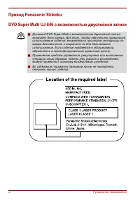
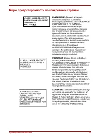

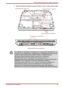

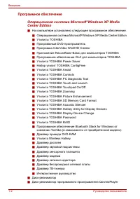
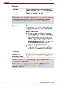
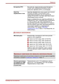
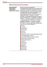
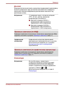
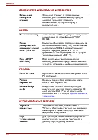
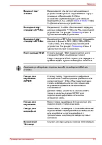
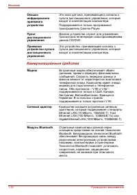
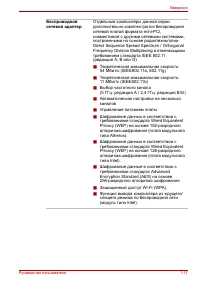
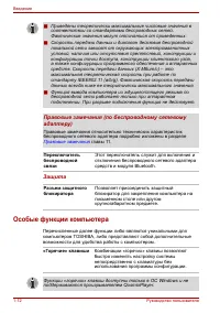
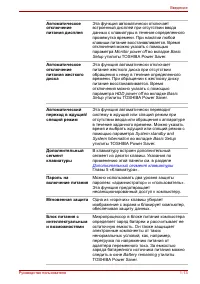
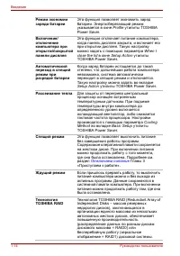
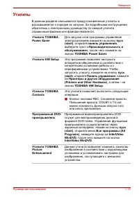


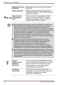
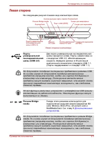
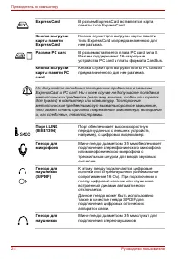
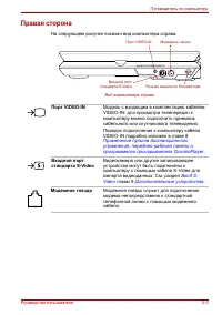
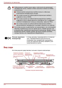
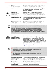
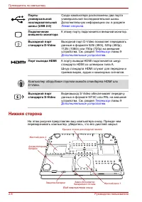
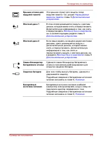
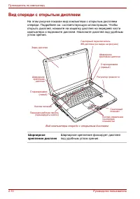
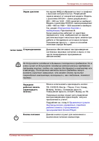
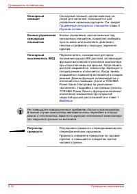
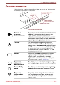
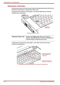
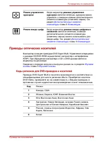
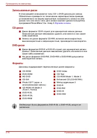
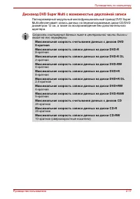
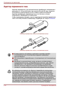

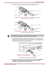
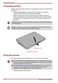
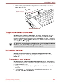
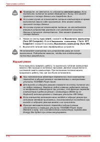

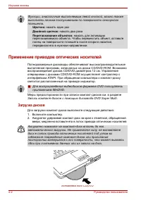
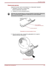
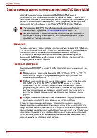

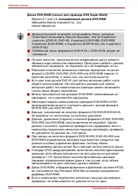

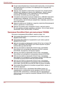
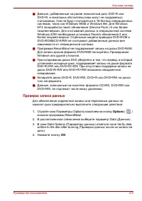

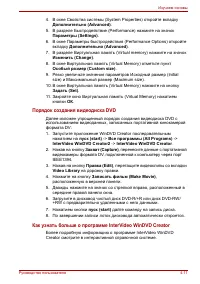

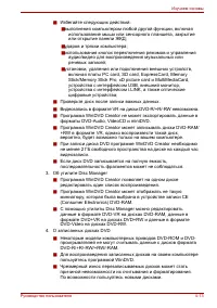
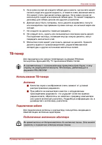
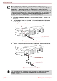
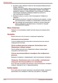
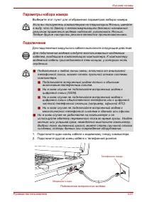
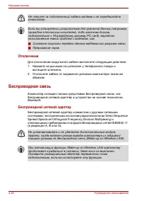
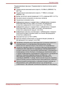
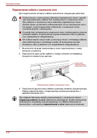

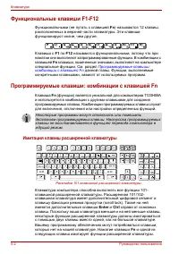
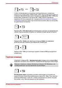
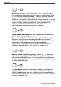
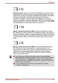
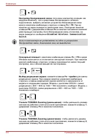

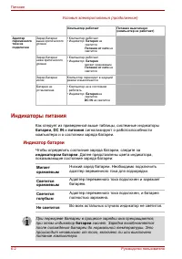
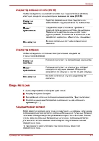
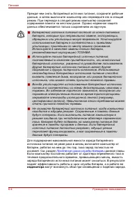
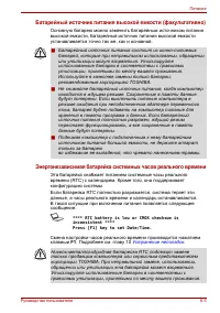
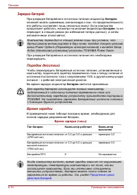
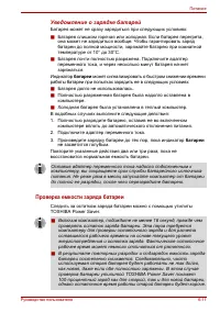
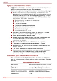
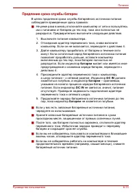
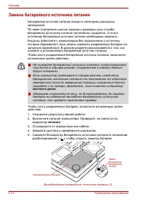
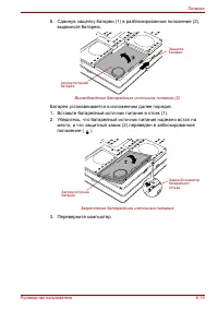
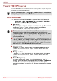
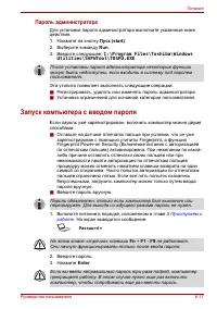
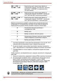
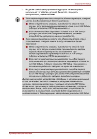
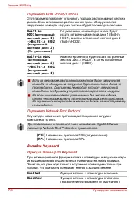
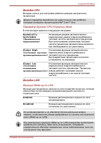
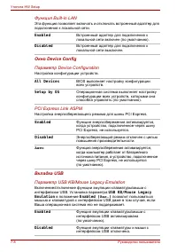
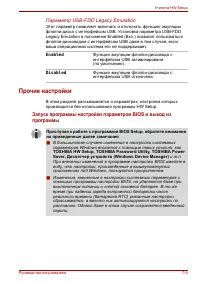
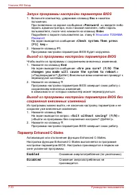
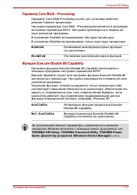
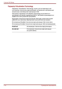
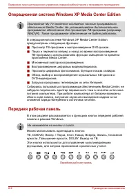
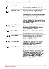
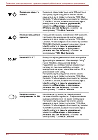
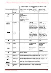

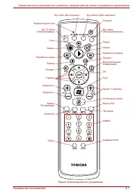
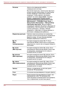
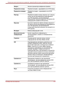
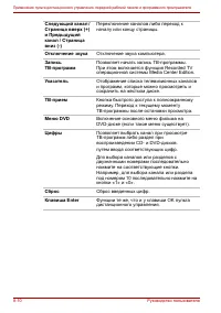
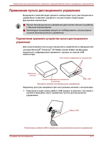
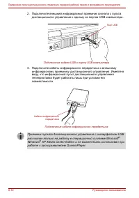
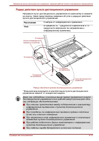
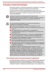
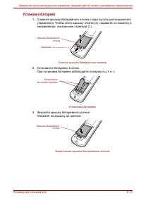
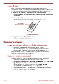
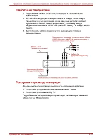
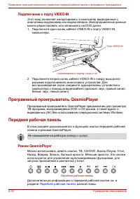
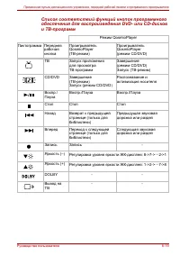
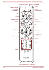
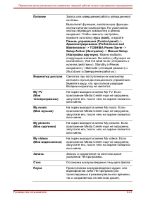
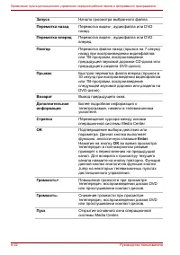
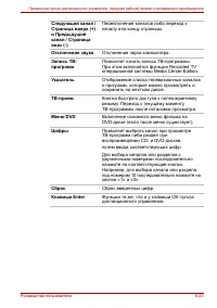
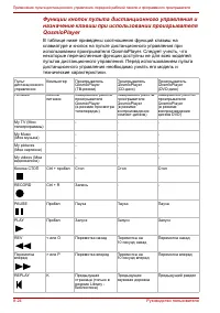
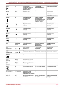
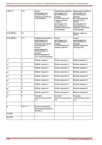
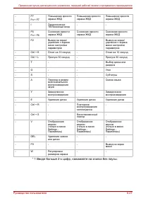
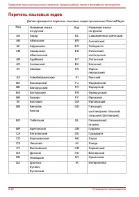
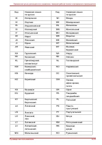
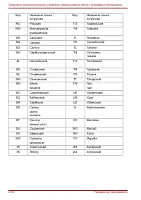
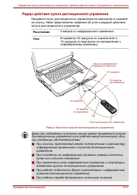
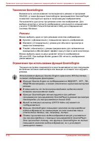
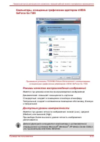

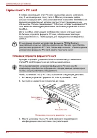
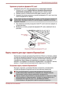
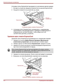
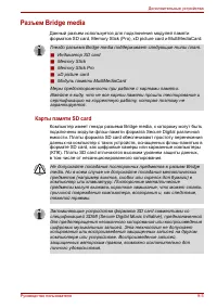
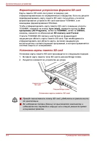
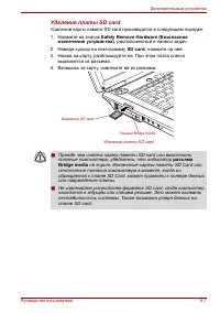
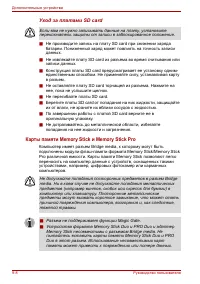
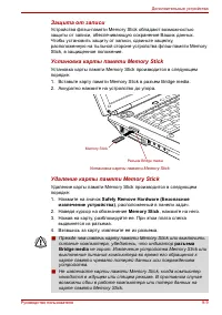
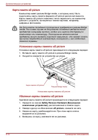
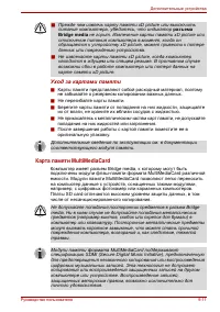
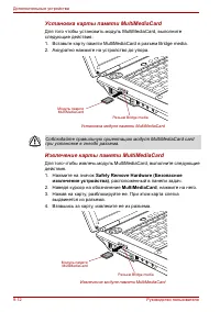
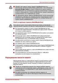
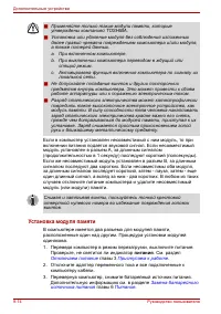
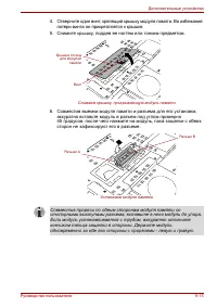
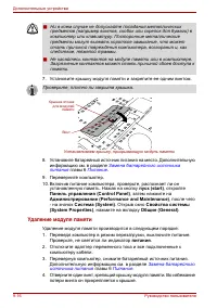
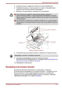
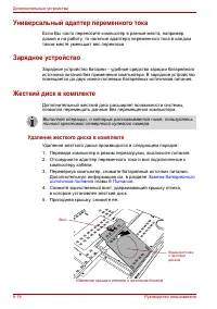
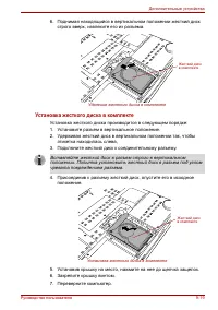
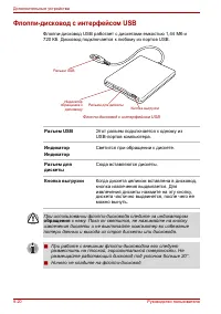
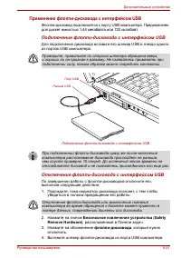
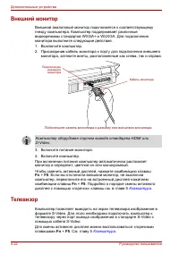
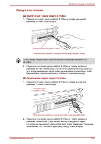
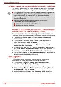
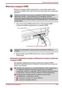
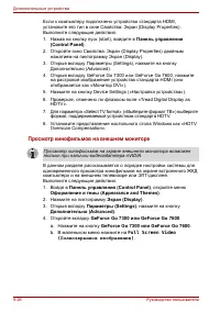
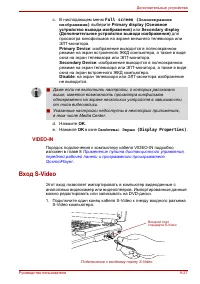
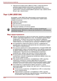
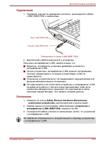
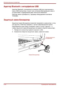
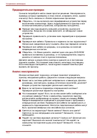
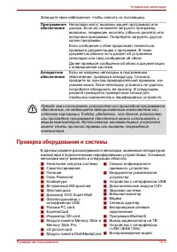

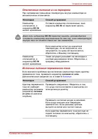

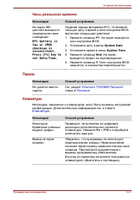
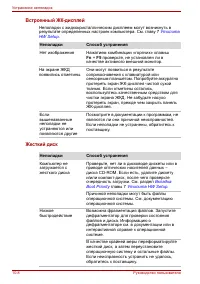
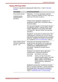
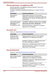
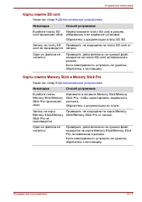
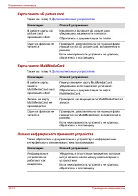
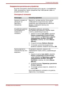
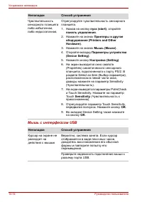
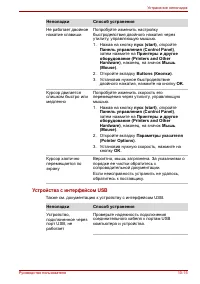
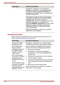
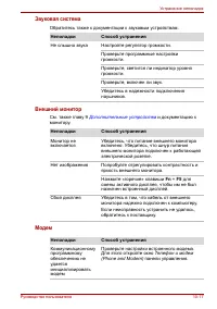
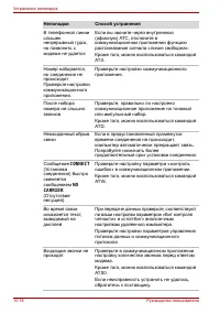
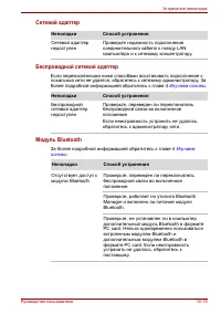
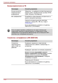
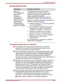
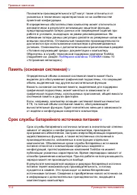
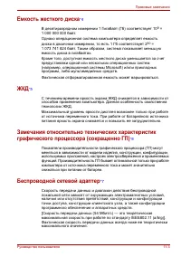

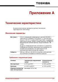
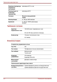
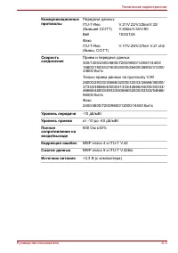

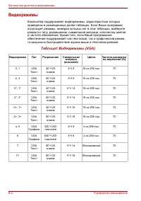
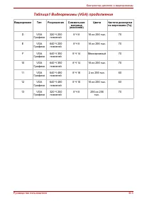
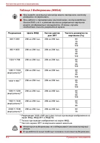
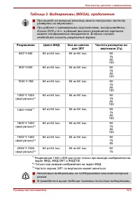
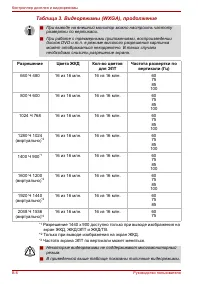
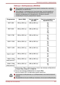
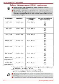
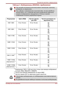
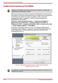
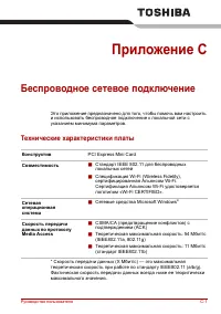
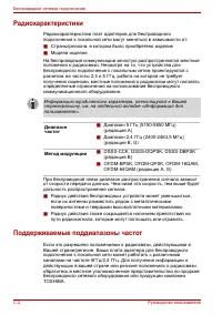
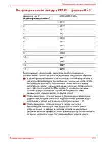
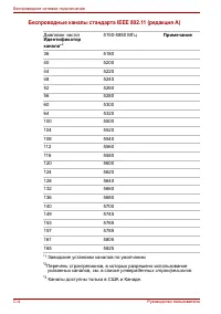
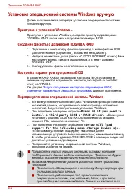
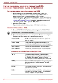
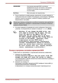


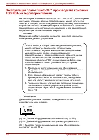

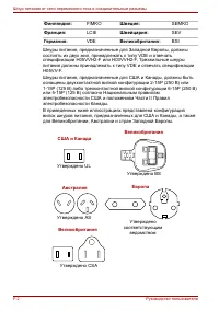


 Toshiba Portege Z830
User Manual
Toshiba Portege Z830
User Manual
 Toshiba Qosmio X300
User Manual
Toshiba Qosmio X300
User Manual
 Toshiba Satellite 5200
User Manual
Toshiba Satellite 5200
User Manual
 Toshiba Satellite A10
User Manual
Toshiba Satellite A10
User Manual
 Toshiba Satellite A100
User Manual
Toshiba Satellite A100
User Manual
 Toshiba Satellite A20
User Manual
Toshiba Satellite A20
User Manual
 Toshiba Satellite A200
User Manual
Toshiba Satellite A200
User Manual
 Toshiba Satellite A210
User Manual
Toshiba Satellite A210
User Manual
 Toshiba Satellite A40
User Manual
Toshiba Satellite A40
User Manual
 Toshiba Satellite A50
User Manual
Toshiba Satellite A50
User Manual
 Toshiba Satellite A60
User Manual
Toshiba Satellite A60
User Manual
 Toshiba Satellite C670 (D)
User Manual
Toshiba Satellite C670 (D)
User Manual
 Toshiba Satellite L100
User Manual
Toshiba Satellite L100
User Manual
 Toshiba Satellite L20
User Manual
Toshiba Satellite L20
User Manual
 Toshiba Satellite L30
User Manual
Toshiba Satellite L30
User Manual
 Toshiba Satellite L40
User Manual
Toshiba Satellite L40
User Manual
 Toshiba Satellite L775 (D)
User Manual
Toshiba Satellite L775 (D)
User Manual
 Toshiba Satellite M100
User Manual
Toshiba Satellite M100
User Manual