Timberk T-GS4-G10 - Manuals
User Manual Timberk T-GS4-G10


Summary
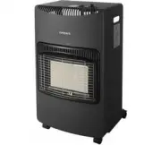
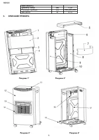
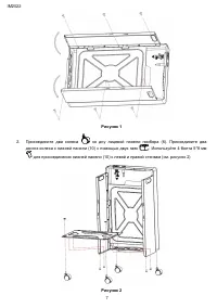
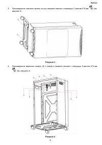
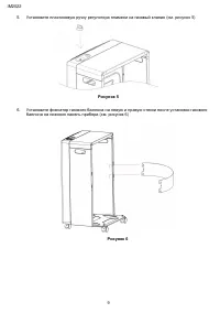
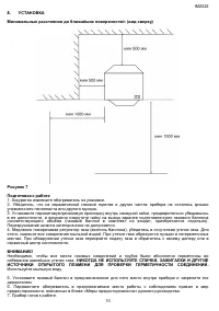
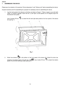
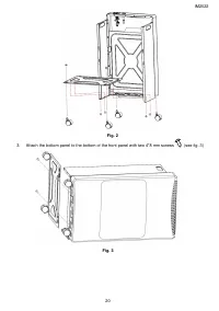
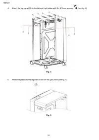
IM2022 7 Рисунок 1 2. Присоедините два колеса ко дну лицевой панели прибора (6). Присоедините два других колеса к нижней панели (10) с помощью двух гаек . Используйте 4 болта 5*8 мм для присоединения нижней панели (10) к левой и правой стенкам (см. рисунок 2) Рисунок 2
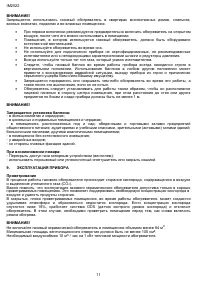
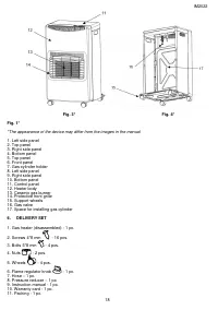
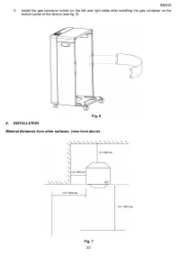
IM2022 10 8. УСТАНОВКА Минимальные расстояния до ближайших поверхностей: (вид сверху) Рисунок 7 Подготовка к работе 1. Аккуратно извлеките обогреватель из упаковки. 2. Убедитесь, что на керамической газовой горелке и других частях прибора не осталось крошки упаковочного пенопласта или другого мусора...
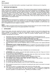
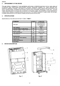
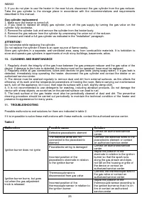
IM2022 15 Dear customer! We thank you for your wise choice and for a purchase of a gas heater. It will serve you for a long time. 1. IMPORTANT INFORMATION Please, read this manual before using the device. This manual contains important information regarding your safety, as well as recommendations co...
Timberk Heaters Manuals
-
 Timberk Mini TGH 4200 SM1
User Manual
Timberk Mini TGH 4200 SM1
User Manual
-
 Timberk T-CH1.2-A11
User Manual
Timberk T-CH1.2-A11
User Manual
-
 Timberk T-CH1.5-A10
User Manual
Timberk T-CH1.5-A10
User Manual
-
 Timberk T-CH2.0-A10
User Manual
Timberk T-CH2.0-A10
User Manual
-
 Timberk TFH I15MDR
User Manual
Timberk TFH I15MDR
User Manual
-
 Timberk T-FH1.2-B10MC-B
User Manual
Timberk T-FH1.2-B10MC-B
User Manual
-
 Timberk T-FH2-B10S-B
User Manual
Timberk T-FH2-B10S-B
User Manual
-
 Timberk TGH 4200 O2
User Manual
Timberk TGH 4200 O2
User Manual
-
 Timberk TGH 4200 O3
User Manual
Timberk TGH 4200 O3
User Manual
-
 Timberk THC WS1 3M
User Manual
Timberk THC WS1 3M
User Manual
-
 Timberk THC WS1 5M
User Manual
Timberk THC WS1 5M
User Manual
-
 Timberk THC WS1 6M
User Manual
Timberk THC WS1 6M
User Manual
-
 Timberk THC WS1 9M
User Manual
Timberk THC WS1 9M
User Manual
-
 Timberk THC WS2 3M AERO
User Manual
Timberk THC WS2 3M AERO
User Manual
-
 Timberk THC WT1 5M
User Manual
Timberk THC WT1 5M
User Manual
-
 Timberk T-HG2-Q10T
User Manual
Timberk T-HG2-Q10T
User Manual
-
 Timberk T-HG2-Q11T
User Manual
Timberk T-HG2-Q11T
User Manual
-
 Timberk T-HG2-Q15M
User Manual
Timberk T-HG2-Q15M
User Manual
-
 Timberk T-HG3-Q12T
User Manual
Timberk T-HG3-Q12T
User Manual
-
 Timberk T-HG3-Q15M
User Manual
Timberk T-HG3-Q15M
User Manual