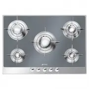
Page 2 - Instructions; General safety instructions; Risk of personal injury
Instructions 4 1 Instructions 1.1 General safety instructions Risk of personal injury • During use the appliance and its accessible parts become very hot. • Never touch the heating elements during use. • Keep children under eight years of age at a safe distance if they are not constantly supervised....
Page 3 - • Never leave objects on the; Identification plate; Power voltage
Instructions 5 EN • Never leave objects on the cooking surface. • Do not use the appliance to heat rooms for any reason. 1.2 Identification plate • The identification plate bears the technical data, serial number and brand name of the appliance. Do not remove the identification plate for any reason....
Page 4 - How to read the user manual; Danger of suffocation
Instructions 6 Our appliances are packed in non-polluting and recyclable materials.• Consign the packing materials to the appropriate selective collection centres. 1.6 This user manual This user manual is an integral part of the appliance and must therefore be kept in its entirety and within the use...
Page 5 - Description; General Description
Description 7 EN 2 Description 2.1 General Description 60 cm 75 cm
Page 6 - Cooking zones
Description 8 100 cm AUX = AuxiliarySR = Semi-rapidRR = Reduced rapid R = RapidUR = Ultra rapid 2.2 Symbols Cooking zones Front left Centre left Rear left Central Rear right Central right Front right Burner knobs Useful for lighting and adjusting the hob burners. Press and turn the knobs anti- clock...
Page 7 - Use; Improper use
Use 9 EN 3 Use 3.1 Instructions 3.2 First use 1. Remove any protective film from the outside or inside of the appliance, including accessories. 2. Remove any labels (apart from the technical data plate) from accessories. 3. Remove and wash all the appliance accessories (see 4 Cleaning and maintenanc...
Page 8 - and wait 60 seconds before trying
Use 10 3.3 Using the hob All the appliance’s control and monitoring devices are located together on the front panel. The burner controlled by each knob is shown next to the knob. The appliance is equipped with an electronic ignition device. Simply press the knob and turn it anti-clockwise to the max...
Page 9 - Correct positioning of the grids
Use 11 EN Correct positioning of the grids The grids over the burners must be positioned in parallel to the control panel, not perpendicular.Each type of burner must be associated with its own grid.Use the igniter and thermocouple indentations as a reference in order to correctly position the grid o...
Page 10 - Cleaning and maintenance; Cleaning the appliance; Ordinary daily cleaning
Cleaning and maintenance 12 4 Cleaning and maintenance 4.1 Instructions 4.2 Cleaning the appliance To keep the surfaces in good condition, they should be cleaned regularly after use. Let them cool first. Ordinary daily cleaning Always use only specific products that do not contain abrasives or chlor...
Page 11 - Igniters and thermocouples
Cleaning and maintenance 13 EN Igniters and thermocouples For correct operation the igniters and thermocouples must always be perfectly clean. Check them frequently and clean them with a damp cloth if necessary. Remove any dry residues with a wooden toothpick or a needle. Flame-spreader crowns and b...
Page 12 - Installation; Clearances above and around domestic appliances; Requirements
Installation 14 5 Installation 5.1 Clearances above and around domestic appliances This appliance must be installed by an authorised person in accordance with this instruction manual, AS/NZS 5601.1 – Gas installations (installation and pipe sizing), local gas fitting regulations, local electrical re...
Page 13 - Additional requirements for; Safety instructions; Risk of fire
Installation 15 EN 3. Additional requirements for Freestanding and Elevated Cooking Appliaces – (Measurements D & E) Where D, the distance from the periphery of the nearest burner to a horizontal combustible surface is less than 200 mm, then E shall be 10 mm or more, or the horizontal surface sh...
Page 14 - Section cut from the countertop; Over built-in oven unit; opens on bottom
Installation 16 5.3 Section cut from the countertop Create an opening with the dimensions shown in the figure in the countertop of the piece of furniture. 5.4 Mounting Over built-in oven unit The clearance between the hob and the kitchen furniture or other installed appliances must be enough to ensu...
Page 15 - Over empty kitchen unit or drawers; required for gas connection; Fixing brackets
Installation 17 EN Over empty kitchen unit or drawers If there are other pieces of furniture (lateral walls, drawers, etc.), dishwashers or fridges under the hob, a double-layer wooden base must be installed at least 20 mm from the bottom of the hob to avoid any accidental contact. It must only be p...
Page 16 - With steel hob
Installation 18 With steel hob To prevent leakage of liquid between the frame of the hob and the work surface, put the insulating seal provided in position before assembly.1. Refer to the dimensions in the figure, bearing in mind that the long front side must brush against the hole. 2. Use light pre...
Page 17 - The regulator must be fitted to the 1⁄2
Installation 19 EN Connection of the appliance to the gas supply must be in accordance with the requirements of AS5601. A ½” BSP connector at the inlet is recommended and the gas supply line to the appliance must be of adequate length to allow sufficient withdrawal of appliance for service or discon...
Page 18 - Room ventilation
Installation 20 Room ventilation The room containing the appliance should have a permanent air supply in accordance with the standards in force. The room where the appliance is installed must have enough air flow needed for the regular combustion of gas and the necessary air change in the room itsel...
Page 19 - Adaptation to different types of gas; Removing the hob top
Installation 21 EN 5.6 Adaptation to different types of gas If other types of gas are to be used, the nozzles must be replaced and the primary air must be adjusted. In order to replace the nozzles and adjust the burners, the hob top must be removed. Removing the hob top 1. Remove the grids from the ...
Page 20 - Replacing nozzles
Installation 22 5. Remove the screws that fasten the hob top to the burner casing (the figure shows the 60 cm model as an example). 6. Lift the hob top and remove it. Replacing nozzles 1. Unscrew screw A and push air regulator B as far as it will go. 2. Use a spanner to remove the nozzles C and inst...
Page 21 - Light the burner and turn it to the minimum
Installation 23 EN Adjusting the minimum setting for natural or town gas 1. Light the burner and turn it to the minimum position. 2. Extract the gas cock knob and turn the adjustment screw next to the tap rod (depending on the model) until the correct minimum flame is achieved. 3. Refit the knob and...
Page 22 - Electrical connection; General information
Installation 24 5.7 Electrical connection General information Check the grid characteristics against the data indicated on the plate.The identification plate bearing the technical data, serial number and brand name is visibly positioned on the appliance.Do not remove this plate for any reason.Perfor...