Smeg PV395LNAU - Manuals
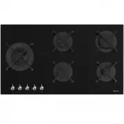
User Manual Smeg PV395LNAU


Summary
Instructions 4 1 Instructions 1.1 General safety instructions Risk of personal injury • During use the appliance becomes hot. Care should be taken to avoid touching heating elements inside the oven. • WARNING - Accessible parts will become hot when in use. To avoid burns young children should be kep...
Instructions 5 EN • DO NOT USE OR STORE FLAMMABLE MATERIALS NEAR THE APPLIANCE. • NEVER USE AEROSOL CANS NEAR THE APPLIANCE WHILE IT IS IN OPERATION. • Switch the appliance off immediately after use. • DO NOT MODIFY THIS APPLIANCE. • Before carrying out any work on the appliance (installation, maint...
Instructions 6 • All cookware must have smooth, flat bottoms. • If any liquid does boil over or spill, remove the excess from the cooktop. • Take care not to spill acidic substances such as lemon juice or vinegar onto the cooktop. • Do not put empty pans or frying pans on switched on cooking zones. ...
Smeg Hobs Manuals
-
 Smeg CIR574X3
User Manual
Smeg CIR574X3
User Manual
-
 Smeg CIR574XS3
User Manual
Smeg CIR574XS3
User Manual
-
 Smeg CIR575X
User Manual
Smeg CIR575X
User Manual
-
Smeg CIR575X
Manual
-
 Smeg CIR597XS
User Manual
Smeg CIR597XS
User Manual
-
 Smeg CIR60X
User Manual
Smeg CIR60X
User Manual
-
Smeg CIR60X
Manual
-
 Smeg CIR60XS3
User Manual
Smeg CIR60XS3
User Manual
-
 Smeg HOBD182DG
User Manual
Smeg HOBD182DG
User Manual
-
 Smeg HOBD682D1
User Manual
Smeg HOBD682D1
User Manual
-
 Smeg P106
User Manual
Smeg P106
User Manual
-
Smeg P106
Manual
-
 Smeg P1641XA
User Manual
Smeg P1641XA
User Manual
-
 Smeg P64
User Manual
Smeg P64
User Manual
-
 Smeg P652
User Manual
Smeg P652
User Manual
-
Smeg P652
Manual
-
 Smeg P663-1
User Manual
Smeg P663-1
User Manual
-
 Smeg P705ES
User Manual
Smeg P705ES
User Manual
-
 Smeg P705VT
User Manual
Smeg P705VT
User Manual
-
Smeg P705VT
Manual