Smeg P755AXA-1 - Manuals
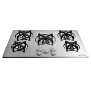
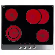
User Manual Smeg P755AXA-1


Summary
ENGLISH 3 - 26 Thank you for choosing our product. We advise you to read this manual carefully. It contains all necessary instructions for maintaining unaltered the appearance and functional qualities of the oven.
Contents 1. INSTRUCTIONS FOR USE ................................................................ 4 2. SAFETY PRECAUTIONS ................................................................... 6 3. ENVIRONMENTAL RESPONSIBILITY ............................................... 8 4. DESCRIPTION OF CONTROLS...
General instructions 1. INSTRUCTIONS FOR USE THIS MANUAL IS AN INTEGRAL PART OF THE APPLIANCE. IT MUST BE KEPT IN ITS ENTIRETY AND IN AN ACCESSIBLE PLACE FOR THE WHOLE WORKING LIFE OF THE HOB. WE ADVISE YOU TO READ THIS MANUAL AND ALL THE INFORMATION IT CONTAINS CAREFULLY BEFORE USING THE HOB. ALSO ...
Smeg Hobs Manuals
-
 Smeg CIR574X3
User Manual
Smeg CIR574X3
User Manual
-
 Smeg CIR574XS3
User Manual
Smeg CIR574XS3
User Manual
-
 Smeg CIR575X
User Manual
Smeg CIR575X
User Manual
-
Smeg CIR575X
Manual
-
 Smeg CIR597XS
User Manual
Smeg CIR597XS
User Manual
-
 Smeg CIR60X
User Manual
Smeg CIR60X
User Manual
-
Smeg CIR60X
Manual
-
 Smeg CIR60XS3
User Manual
Smeg CIR60XS3
User Manual
-
 Smeg HOBD182DG
User Manual
Smeg HOBD182DG
User Manual
-
 Smeg HOBD682D1
User Manual
Smeg HOBD682D1
User Manual
-
 Smeg P106
User Manual
Smeg P106
User Manual
-
Smeg P106
Manual
-
 Smeg P1641XA
User Manual
Smeg P1641XA
User Manual
-
 Smeg P64
User Manual
Smeg P64
User Manual
-
 Smeg P652
User Manual
Smeg P652
User Manual
-
Smeg P652
Manual
-
 Smeg P663-1
User Manual
Smeg P663-1
User Manual
-
 Smeg P705ES
User Manual
Smeg P705ES
User Manual
-
 Smeg P705VT
User Manual
Smeg P705VT
User Manual
-
Smeg P705VT
Manual