Page 2 - Instructions; General safety instructions
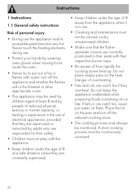
Instructions 50 1 Instructions 1.1 General safety instructions Risk of personal injury • During use the appliance and its accessible parts become very hot. Never touch the heating elements during use. • Protect your hands by wearing oven gloves when moving food inside the oven. • Never try to put ou...
Page 4 - Risk of damaging the appliance
Instructions 52 Risk of damaging the appliance • Do not use abrasive or corrosive detergents (e.g. scouring powders, stain removers and metallic sponges) on glass parts. • Use wooden or plastic utensils.• Racks and trays should be inserted as far as they will go into the side guides. The mechanical ...
Page 5 - Installation
Instructions 53 EN • All pans must have smooth, flat bottoms. • If any liquid does boil over or spill, remove the excess from the hob. • Take care not to spill acid substances such as lemon juice or vinegar on the hob. • Do not put empty pans or frying pans on switched on cooking zones. • Do not use...
Page 6 - For this appliance
Instructions 54 • Installation using a hose must be carried out so that the length of the hose does not exceed 2 metres when fully extended for steel hoses and 1.5 metres for rubber hoses. • The hoses should not come into contact with moving parts and should not be crushed in any way. • If required,...
Page 7 - Appliance purpose
Instructions 55 EN 1.3 Appliance purpose • This appliance is intended for cooking food in the home environment. Every other use is considered inappropriate. • The appliance is not designed to operate with external timers or with remote-control systems. 1.4 Identification plate The identification pla...
Page 8 - • Deliver the appliance to the; How to read the user manual; Plastic packaging
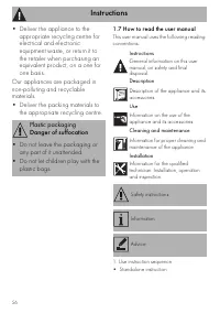
Instructions 56 • Deliver the appliance to the appropriate recycling centre for electrical and electronic equipment waste, or return it to the retailer when purchasing an equivalent product, on a one for one basis. Our appliances are packaged in non-polluting and recyclable materials.• Deliver the p...
Page 9 - Description; General Description
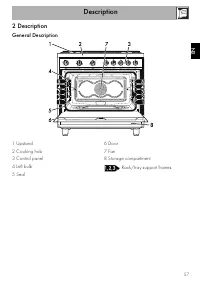
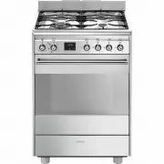
Description 57 EN 2 Description General Description 1 Upstand 2 Cooking hob 3 Control panel 4 Left bulb 5 Seal 6 Door 7 Fan 8 Storage compartment Rack/tray support frames
Page 10 - AUX
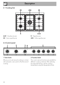
Description 58 2.1 Cooking hob AUX = Auxiliary burner SR = Semi-rapid burner R = Rapid burner UR2 = Ultra-rapid burner 2.2 Control panel 1 Timer knob Allows you to set manual cooking or a timer with automatic oven switch off at the end of cooking. 2 Function knob The oven's various functions are sui...
Page 12 - Available accessories; Deep tray
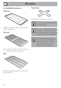
Description 60 2.4 Available accessories Deep tray Useful for collecting fat from foods placed on the rack above. Tray rack To be placed over the top of the oven tray; for cooking foods which may drip. Rack Used for supporting containers with food during cooking. Ring reducer Useful when using small...
Page 13 - Use
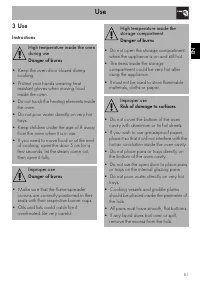
Use 61 EN 3 Use Instructions High temperature inside the oven during use Danger of burns • Keep the oven door closed during cooking. • Protect your hands wearing heat resistant gloves when moving food inside the oven. • Do not touch the heating elements inside the oven. • Do not pour water directly ...
Page 14 - Precautions
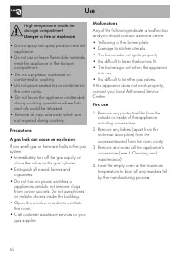
Use 62 Precautions A gas leak can cause an explosion. If you smell gas or there are faults in the gas system:• Immediately turn off the gas supply or close the valve on the gas cylinder. • Extinguish all naked flames and cigarettes. • Do not turn on power switches or appliances and do not remove plu...
Page 15 - Using the accessories; Ring reducers
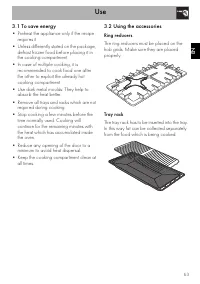
Use 63 EN 3.1 To save energy • Preheat the appliance only if the recipe requires it. • Unless differently stated on the package, defrost frozen food before placing it in the cooking compartment. • In case of multiple cooking, it is recommended to cook food one after the other to exploit the already ...
Page 16 - Racks and trays
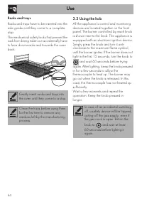
Use 64 Racks and trays Racks and trays have to be inserted into the side guides until they come to a complete stop.The mechanical safety locks that prevent the rack from being taken out accidentally have to face downwards and towards the oven back. 3.3 Using the hob All the appliance’s control and m...
Page 17 - Practical tips for using the hob; Using the storage compartment; Switching on the oven
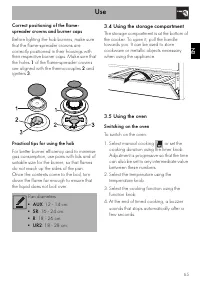
Use 65 EN Correct positioning of the flame-spreader crowns and burner caps Before lighting the hob burners, make sure that the flame-spreader crowns are correctly positioned in their housings with their respective burner caps. Make sure that the holes 1 of the flame-spreader crowns are aligned with ...
Page 18 - Functions list
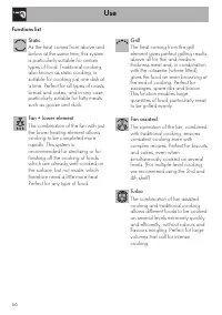
Use 66 Functions list Static As the heat comes from above and below at the same time, this system is particularly suitable for certain types of food. Traditional cooking, also known as static cooking, is suitable for cooking just one dish at a time. Perfect for all types of roasts, bread and cakes, ...
Page 19 - General advice
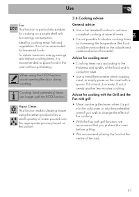
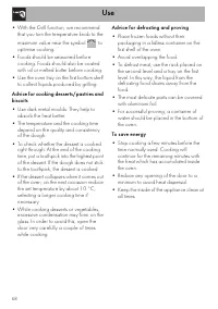
Use 67 EN 3.6 Cooking advice General advice • Use a fan assisted function to achieve consistent cooking at several levels. • It is not possible to shorten cooking times by increasing the temperature (the food could be overcooked on the outside and undercooked on the inside). Advice for cooking meat ...
Page 20 - Advice for defrosting and proving
Use 68 • With the Grill function, we recommend that you turn the temperature knob to the maximum value near the symbol to optimise cooking. • Foods should be seasoned before cooking. Foods should also be coated with oil or melted butter before cooking. • Use the oven tray on the first bottom shelf t...
Page 21 - Cooking information table
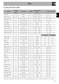
Use 69 EN Cooking information table Food Weight (kg) Function Shelf Temperature (°C) Time (minutes) Lasagne 3 - 4 Static 1 220 - 230 45 - 50 Pasta bake 3 - 4 Static 1 220 - 230 45 - 50 Roasted veal 2 Turbo/Round 2 180 - 190 90 - 100 Pork loin 2 Turbo/Round 2 180 - 190 70 - 80 Sausages 1.5 Fan with g...
Page 22 - Cleaning and maintenance
Cleaning and maintenance 70 4 Cleaning and maintenance Instructions Cleaning the surfaces To keep the surfaces in good condition, they should be cleaned regularly after use. Let them cool first. Ordinary daily cleaning Always use specific products only that do not contain abrasives or chlorine-based...
Page 23 - Cooking hob grids
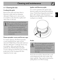
Cleaning and maintenance 71 EN 4.1 Cleaning the hob Cooking hob grids Remove the grids and clean them in lukewarm water and non-abrasive detergent. Make sure to remove any encrustations. Dry them thoroughly and return them to the hob. Flame-spreader crowns and burner caps For easier cleaning, the fl...
Page 24 - Cleaning the door; Removing the door
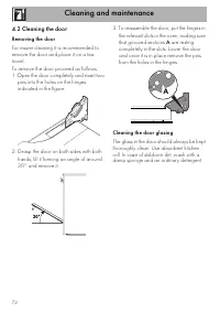
Cleaning and maintenance 72 4.2 Cleaning the door Removing the door For easier cleaning it is recommended to remove the door and place it on a tea towel.To remove the door proceed as follows:1. Open the door completely and insert two pins into the holes on the hinges indicated in the figure. 2. Gras...
Page 25 - Removing the internal glass panes
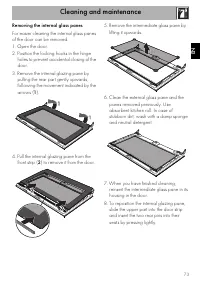
Cleaning and maintenance 73 EN Removing the internal glass panes For easier cleaning the internal glass panes of the door can be removed.1. Open the door.2. Position the locking hooks in the hinge holes to prevent accidental closing of the door. 3. Remove the internal glazing pane by pulling the rea...
Page 26 - Cleaning the oven cavity; Removing racks/trays support frames
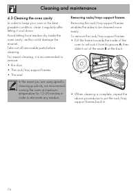
Cleaning and maintenance 74 4.3 Cleaning the oven cavity In order to keep your oven in the best possible condition, clean it regularly after letting it cool down.Avoid letting food residue dry inside the oven cavity, as this could damage the enamel.Take out all removable parts before cleaning.For ea...
Page 27 - Preliminary operations
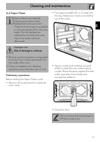
Cleaning and maintenance 75 EN 4.4 Vapor Clean Preliminary operations Before starting the Vapor Clean cycle:• Remove all accessories from inside the oven cavity. • Pour approximately 40 cc of water into the tray. Make sure it does not overflow out of the cavity. • Spray a water and washing up liquid...
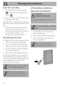
Page 28 - Vapor Clean cycle setting; Extraordinary maintenance; Replacing the internal light bulb
Cleaning and maintenance 76 Vapor Clean cycle setting 1. Turn the function knob to the symbol and the temperature knob to the symbol . 2. Set a cooking time of 18 minutes using the programmer clock. The Vapor Clean cycle starts a few seconds after the last press on the programmer clock keys.3. At th...
Page 29 - Refit the cover. Ensure the moulded part
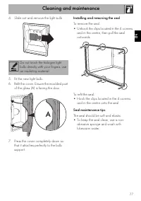
Cleaning and maintenance 77 EN 4. Slide out and remove the light bulb. 5. Fit the new light bulb. 6. Refit the cover. Ensure the moulded part of the glass (A) is facing the door. 7. Press the cover completely down so that it attaches perfectly to the bulb support. Installing and removing the seal To...
Page 30 - Installation; General information
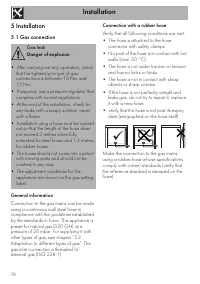
Installation 78 5 Installation 5.1 Gas connection General information Connection to the gas mains can be made using a continuous wall steel hose in compliance with the guidelines established by the standards in force. The appliance is preset for natural gas G20 (2H) at a pressure of 20 mbar. For sup...
Page 31 - Connection with a steel hose
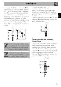
Installation 79 EN Carefully screw the hose connector 3 to the appliance’s gas connector 1 (½” thread ISO 228-1), placing the seal 2 between them. The hose connector 4 can also be screwed to the hose connector 3 , depending on the diameter of the gas hose used. After having tightened the hose connec...
Page 32 - Connection to LPG
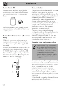
Installation 80 Connection to LPG Use a pressure regulator and make the connection on the gas cylinder following the guidelines set out in the standards in force. The supply pressure must comply with the values indicated in the table in “Gas types and Countries”. Connection with a steel hose with co...
Page 33 - Adaptation to different types of; Replacing nozzles
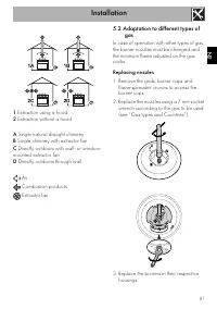
Installation 81 EN 1 Extraction using a hood 2 Extraction without a hood A Single natural draught chimney B Single chimney with extractor fan C Directly outdoors with wall- or window- mounted extractor fan D Directly outdoors through wall Air Combustion products Extractor fan 5.2 Adaptation to diffe...
Page 34 - Adjusting the minimum setting for LPG
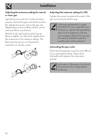
Installation 82 Adjusting the minimum setting for natural or town gas Light the burner and turn it to the minimum position. Extract the gas cock knob and turn the adjustment screw next to the tap rod (depending on the model) until the correct minimum flame is achieved.Refit the knob and verify that ...
Page 35 - Gas types and Countries; SE RU DK PL HU
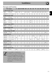
Installation 83 EN Gas types and Countries Gas types IT GB-IE FR-BE DE AT NL ES PT SE RU DK PL HU 1 Natural gas G20 G20 20 mbar • • • • • • • • • • G20/25 20/25 mbar • 2 Natural gas G20 G20 25 mbar • 3 Natural gas G25 G25 25 mbar • G25.3 25 mbar • 4 Natural gas G25.1 G25.1 25 mbar • 5 Natural gas G2...
Page 36 - Burner and nozzle characteristics tables
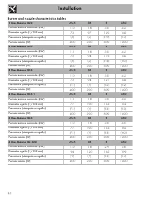
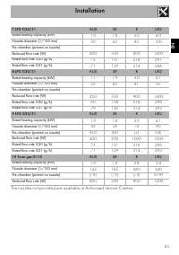
Installation 84 Burner and nozzle characteristics tables 1 Gas Metano G20 AUX SR R UR2 Portata termica nominale (kW) 1.0 1.8 3.0 4.2 Diametro ugello (1/100 mm) 72 97 120 145 Precamera (stampata su ugello) (X) (Z) (H9) (F3) Portata ridotta (W) 400 500 800 1400 2 Gas Metano G20 AUX SR R UR2 Portata te...
Page 38 - Heavy appliance
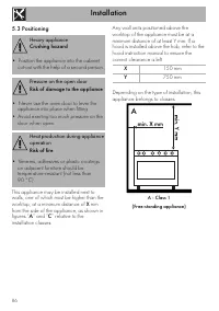
Installation 86 5.3 Positioning This appliance may be installed next to walls, one of which must be higher than the worktop, at a minimum distance of X mm from the side of the appliance, as shown in figures “ A ” and “ C ” relative to the installation classes. Any wall units positioned above the wor...
Page 39 - B - Class 2 subclass 1; Appliance overall dimensions
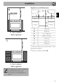
Installation 87 EN B - Class 2 subclass 1 (Built-in appliance) C - Class 2 subclass 1 (Built-in appliance) Appliance overall dimensions 1 Minimum distance from side walls or other flammable material. 2 Minimum cabinet width ( =A ). The appliance must be installed by a qualified technician and accord...
Page 40 - Electrical connection
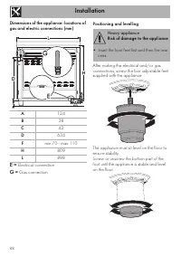
Installation 88 Dimensions of the appliance: locations of gas and electric connections (mm) E = Electrical connection G = Gas connection Positioning and levelling After making the electrical and/or gas connections, screw the four adjustable feet supplied with the appliance. The appliance must sit le...
Page 41 - Fastening to the wall
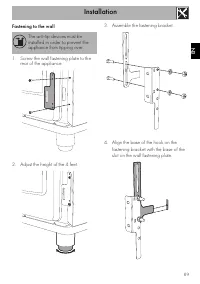
Installation 89 EN Fastening to the wall 1. Screw the wall fastening plate to the rear of the appliance. 2. Adjust the height of the 4 feet. 3. Assemble the fastening bracket. 4. Align the base of the hook on the fastening bracket with the base of the slot on the wall fastening plate. The anti-tip d...
Page 42 - Align the base of the fastening bracket
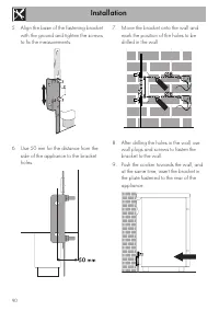
Installation 90 5. Align the base of the fastening bracket with the ground and tighten the screws to fix the measurements. 6. Use 50 mm for the distance from the side of the appliance to the bracket holes. 7. Move the bracket onto the wall and mark the position of the holes to be drilled in the wall...
Page 43 - Assembling the upstand; Electrical connection
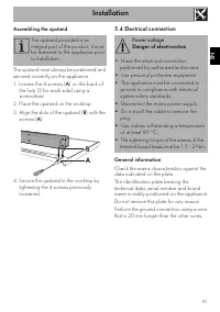
Installation 91 EN Assembling the upstand The upstand must always be positioned and secured correctly on the appliance.1. Loosen the 4 screws ( A ) on the back of the hob (2 for each side) using a screwdriver. 2. Place the upstand on the worktop. 3. Align the slots of the upstand ( B ) with the scre...
Page 44 - Fixed connection
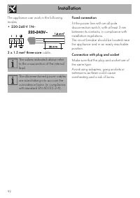
Installation 92 The appliance can work in the following modes:• 220-240 V 1N ~ 3 x 1.5 mm² three-core cable. Fixed connection Fit the power line with an all-pole disconnection switch, with at least 3 mm between its contacts, in compliance with installation regulations.The circuit breaker should be l...
Page 45 - Instructions for the installer
Installation 93 EN 5.5 Instructions for the installer • The plug must be accessible after installation. Do not bend or trap the power cable. • The appliance must be installed according to the installation diagrams. • Do not try to unscrew or force the threaded elbow of the fitting. You may damage th...

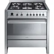
 Smeg A1C-6
User Manual
Smeg A1C-6
User Manual
 Smeg A1C-7
User Manual
Smeg A1C-7
User Manual
 Smeg A2-8
User Manual
Smeg A2-8
User Manual
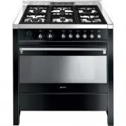
 Smeg A2BL-8
User Manual
Smeg A2BL-8
User Manual
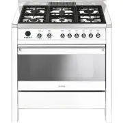
 Smeg A5-8
User Manual
Smeg A5-8
User Manual
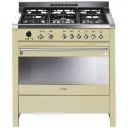
 Smeg C95GMCA9-1
User Manual
Smeg C95GMCA9-1
User Manual
 Smeg CPF30UGGWH
User Manual
Smeg CPF30UGGWH
User Manual
 Smeg CPF36UGGWH
User Manual
Smeg CPF36UGGWH
User Manual
 Smeg CPF36UGMAN
User Manual
Smeg CPF36UGMAN
User Manual
 Smeg CPF48UGMBL
User Manual
Smeg CPF48UGMBL
User Manual
 Smeg CS19-7
User Manual
Smeg CS19-7
User Manual
 Smeg CS19A-7
User Manual
Smeg CS19A-7
User Manual
 Smeg CS19B-6
User Manual
Smeg CS19B-6
User Manual
 Smeg CS19P-6
User Manual
Smeg CS19P-6
User Manual
 Smeg CS19P-9
User Manual
Smeg CS19P-9
User Manual
 Smeg CS19RW-6
User Manual
Smeg CS19RW-6
User Manual
 Smeg CS19RW-7
User Manual
Smeg CS19RW-7
User Manual
 Smeg CX60ISVT9
User Manual
Smeg CX60ISVT9
User Manual
 Smeg FS61XNG8-1
User Manual
Smeg FS61XNG8-1
User Manual