Siemens 175V - Manuals
Siemens 175V – User Manual in PDF format online.
Manuals:
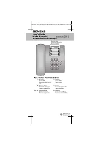
User Manual Siemens 175V


Summary
Siemens SIP · 2008 12 Motor Protection / 7SK80 12 12 /10 Application Fig. 12/7 Function diagram The SIPROTEC Compact 7SK80 unit is anumerical protection relay that can performcontrol and monitoring functions andtherefore provide the user with a cost-effec-tive platform for asset protection, monitor-...
Siemens SIP · 2008 12 Motor Protection / 7SK80 12 12 /11 Application ANSI No. IEC Protection functions 50, 50N I>, I>>, I>>>, I E >, I E >>, I E >>> Instantaneous and definite time-overcurrent protection (phase/neutral) 51, 51N I p , I Ep Inverse time-overcurrent ...
Siemens SIP · 2008 12 Motor Protection / 7SK80 12 12 /12 Protection functions Available inverse-time characteristics C haracteristics acc. to ANSI/IEEE IEC 60255-3 Inverse • • Short inverse • Long inverse • • Moderately inverse • Very inverse • • Extremely inverse • • Time-overcurrent protection(ANS...
Siemens Manuals
-
 Siemens HF35M630/01
User Manual
Siemens HF35M630/01
User Manual
-
Siemens HF35M630/01
Installation Manual
-
 Siemens 1015N-2MFM-1A
Manual
Siemens 1015N-2MFM-1A
Manual
-
 Siemens 108
User Manual
Siemens 108
User Manual
-
 Siemens 11
User Manual
Siemens 11
User Manual
-
 Siemens 1168
User Manual
Siemens 1168
User Manual
-
 Siemens 120 Series
User Manual
Siemens 120 Series
User Manual
-
 Siemens 125-1957
User Manual
Siemens 125-1957
User Manual
-
 Siemens 125-3584T
User Manual
Siemens 125-3584T
User Manual
-
 Siemens 125-5033
User Manual
Siemens 125-5033
User Manual
-
 Siemens 140
User Manual
Siemens 140
User Manual
-
 Siemens 18inc Freezer Tower with Dispenser
User Manual
Siemens 18inc Freezer Tower with Dispenser
User Manual
-
 Siemens 18inc Wine Tower
User Manual
Siemens 18inc Wine Tower
User Manual
-
 Siemens 1G03QB 630G
User Manual
Siemens 1G03QB 630G
User Manual
-
 Siemens 2 D SP
User Manual
Siemens 2 D SP
User Manual
-
 Siemens 2000
User Manual
Siemens 2000
User Manual
-
 Siemens 2010 Tango
User Manual
Siemens 2010 Tango
User Manual
-
 Siemens 2010
User Manual
Siemens 2010
User Manual