Samsung WW10T534DAN - Manuals
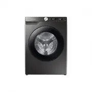
Samsung WW10T534DAN Washing Machine – User Manual, Quick Guide, Repair Manual in PDF format online.
Manuals:
User Manual Samsung WW10T534DAN


Quick Guide Samsung WW10T534DAN


Summary
English 2 Safety information NOTE • Spanner: For removing the shipping bolts and levelling the washing machine.• Bolt caps: For covering the holes after removing the shipping bolts. The provided number of bolt caps (3 to 6) depends on the model. • Hose guide: For hanging the drain hose in the drai...
English 3 Safety information 2. For use in Europe : This appliance can be used by children aged from 8 years and above and persons with reduced physical, sensory or mental capabilities or lack of experience and knowledge if they have been given supervision or instruction concerning use of the appl...
English 4 Safety information ‐ farm houses; ‐ by clients in hotels, motels and other residential type environments; ‐ bed and breakfast type environments; areas for communal use in blocks of flats or in launderettes. Critical installation warnings WARNING The installation of this appliance must be...
Repair Manual Samsung WW10T534DAN


Summary
MODEL CODE WW1*T****** WW7*T****** WW8*T****** WW9*T****** WW10T4040CH WW70T4020CE WW80T4020CE WW80T754ABH WW90T4020CE WW90T734DBT WW10T4040CN WW70T4020CH WW80T4020CX WW80T754ABT WW90T4020EE WW90T734DBX WW10T534DAN WW70T4020CW WW80T4020EE WW80T754DBH WW90T4020EH WW90T734DWH WW10T534DAT WW70T4020CX W...
CONTENTS 1. Safety instructions . . . . . . . . . . . . . . . . . . . . . . . . . . . . . . . . . . . . . . . . . . . . . . . . . . . . . . . . . . . . . . . . . . . . . . . . . 1 1-1. Safety instructions . . . . . . . . . . . . . . . . . . . . . . . . . . . . . . . . . . . . . . . . . . . . . . . ....
Safety Instructions _ 1 1. SAFETY INSTRUCTIONS 1-1. SAFETY INSTRUCTIONS ► Make sure to observe the following instructions to operate the product correctly and safely and prevent possible accidents and hazards while servicing. ► Two types of safety symbols, Warning and Caution, are used in the safety...
Samsung Washing Machines Manuals
-
 Samsung WA10A8376GW
User Manual
Samsung WA10A8376GW
User Manual
-
 Samsung WA10H7200GW
User Manual
Samsung WA10H7200GW
User Manual
-
 Samsung WA10J7700GW
User Manual
Samsung WA10J7700GW
User Manual
-
 Samsung WA10J8700GP
User Manual
Samsung WA10J8700GP
User Manual
-
 Samsung WA10J8700GW
User Manual
Samsung WA10J8700GW
User Manual
-
 Samsung WA11M8700GV
User Manual
Samsung WA11M8700GV
User Manual
-
 Samsung WA12A8376GW
User Manual
Samsung WA12A8376GW
User Manual
-
 Samsung WA13M8700GV
User Manual
Samsung WA13M8700GV
User Manual
-
 Samsung WA13M8700GW
User Manual
Samsung WA13M8700GW
User Manual
-
 Samsung WA14A8377GV
User Manual
Samsung WA14A8377GV
User Manual
-
 Samsung WA14A8377GW
User Manual
Samsung WA14A8377GW
User Manual
-
 Samsung WA40A3005AW
User Manual
Samsung WA40A3005AW
User Manual
-
 Samsung WA40A3005AW/A4
User Manual
Samsung WA40A3005AW/A4
User Manual
-
Samsung WA41A3000AW/A4
User Manual
-
 Samsung WA44A3205AW
User Manual
Samsung WA44A3205AW
User Manual
-
 Samsung WA44A3205AW/A4
User Manual
Samsung WA44A3205AW/A4
User Manual
-
 Samsung WA44A3405AP
User Manual
Samsung WA44A3405AP
User Manual
-
 Samsung WA44A3405AV
User Manual
Samsung WA44A3405AV
User Manual
-
 Samsung WA45T3200AW
User Manual
Samsung WA45T3200AW
User Manual
-
Samsung WA45T3200AW/A4
User Manual