Samsung WD70T4046EW - Manuals
Samsung WD70T4046EW Washing Machine – Repair Manual, Quick Guide in PDF format online.
Manuals:
Repair Manual Samsung WD70T4046EW


Summary
MODEL CODE WD1*T****** WD7*T****** WD8*T****** WD9*T****** WD10T534ABW WD70T4046CH WD80T4046CE WD85T4046CH WD90T4046EH WD10T534DBN WD70T4046EE WD80T4046CW WD85T534DBE WD90T534ABE WD10T534DBT WD70T4046EW WD80T4046CX WD85T554DBW WD90T534ABW WD10T534DBW WD70T4047CE WD80T4046EE WD85T654DBH WD90T534DBN W...
CONTENTS 1. Safety instructions . . . . . . . . . . . . . . . . . . . . . . . . . . . . . . . . . . . . . . . . . . . . . . . . . . . . . . . . . . . . . . . . . . . . . . . . . 1 1-1. Safety instructions . . . . . . . . . . . . . . . . . . . . . . . . . . . . . . . . . . . . . . . . . . . . . . . ....
Safety Instructions _ 1 1. SAFETY INSTRUCTIONS 1-1. SAFETY INSTRUCTIONS ► Make sure to observe the following instructions to operate the product correctly and safely and prevent possible accidents and hazards while servicing. ► Two types of safety symbols, Warning and Caution, are used in the safety...
Quick Guide Samsung WD70T4046EW


Summary
Nützliche Tipps zu Ihrer Trommelwaschmaschine ✔ Die Beschreibungen und Bilder in diesem Dokument können von denen für das von Ihnen tatsächlich gekaufte Gerät abweichen. Weitere Informationen entnehmen Sie bitte dem Benutzerhandbuch. AUFSTELLEN DER WASCHMASCHINE • Wenn Sie Ihre Waschmaschine an eine...
PROBIEREN SIE FOLGENDES... Die Tür öffnet sich nicht Die Tür der Waschmaschine öffnet sich nicht, wenn die Temperatur im Innern zu hoch oder wenn die Trommel noch mit Wasser gefüllt ist. • Wenn die Temperatur der Luft im Innern der Waschmaschine noch höher als 70 °C oder die Wassertemperatur noch üb...
Conseils utiles pour l’utilisation de votre lave-linge à tambour ✔ Le modèle illustré dans ce document peut être différent du vôtre. Pour plus d’informations, consultez votre manuel d’utilisation. INSTALLATION DU LAVE-LINGE • Evitez d’installer votre lave-linge sur un sol glissant ou irrégulier, cel...
Samsung Washing Machines Manuals
-
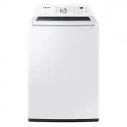
 Samsung WA10J8700GW
User Manual
Samsung WA10J8700GW
User Manual
-
 Samsung WA12A8376GW
User Manual
Samsung WA12A8376GW
User Manual
-
 Samsung WA13M8700GV
User Manual
Samsung WA13M8700GV
User Manual
-
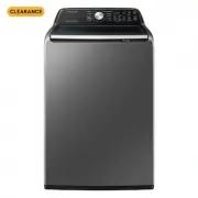
 Samsung WA40A3005AW
User Manual
Samsung WA40A3005AW
User Manual
-
 Samsung WA40A3005AW/A4
User Manual
Samsung WA40A3005AW/A4
User Manual
-
 Samsung WA44A3205AW
User Manual
Samsung WA44A3205AW
User Manual
-
 Samsung WA44A3205AW/A4
User Manual
Samsung WA44A3205AW/A4
User Manual
-
 Samsung WA44A3405AP
User Manual
Samsung WA44A3405AP
User Manual
-
 Samsung WA44A3405AV
User Manual
Samsung WA44A3405AV
User Manual
-
 Samsung WA45T3200AW
User Manual
Samsung WA45T3200AW
User Manual
-
Samsung WA45T3200AW/A4
User Manual
-
 Samsung WA45T3400AP
User Manual
Samsung WA45T3400AP
User Manual
-
 Samsung WA45T3400AV
User Manual
Samsung WA45T3400AV
User Manual
-
 Samsung WA46CG3505AV
User Manual
Samsung WA46CG3505AV
User Manual
-
 Samsung WA46CG3505AVA4
User Manual
Samsung WA46CG3505AVA4
User Manual
-
 Samsung WA46CG3505AW
User Manual
Samsung WA46CG3505AW
User Manual
-
Samsung WA46CG3505AWA4
User Manual
-
 Samsung WA47CG3500AV
User Manual
Samsung WA47CG3500AV
User Manual
-
Samsung WA47CG3500AVA4
User Manual
-
 Samsung WA47CG3500AW
User Manual
Samsung WA47CG3500AW
User Manual