Samsung MIM-D01AN - Manuals
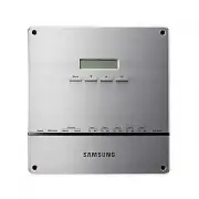
Samsung MIM-D01AN Air Conditioner – User Manual, Installation Manual in PDF format online.
Manuals:
User Manual Samsung MIM-D01AN
Installation Manual Samsung MIM-D01AN
Summary
E- 2 X Do not attempt to install or repair the product by yourself. X The product contains no user-serviceable parts. Always consult authorized service personnel for repairs. X When moving, consult authorized service personnel for disconnection and installation of the product. X Ensure that the wall...
E- 3 X Ne tentez pas d’installer ou de réparer vous-même le produit. X Le produit ne contient aucun composant interne susceptible d’être réparé par l’utilisateur. Consultez toujours le personnel d’entretien agréé pour toute réparation. X En cas de déplacement, consultez le personnel d’entretien agré...
E- 4 Contents X S AFETY P RECAUTIONS .............................. 2 X B EFORE I NSTALLING THE DMS2.5 ....... 5 X A CCESSORIES ............................................. 6 X V IEWING THE P ARTS ................................ 7 X P RODUCT D IMENSIONS ........................... 9 X S YSTEM A RC...
E- 5 Checks before installation 1 DMS2.5 IP X Basically, only Private IP can be set to IP address. To use Public IP, you must set Enable public IP as ‘Enable’ from the menu [System Settings] £ [System environment setting]. - Private IP range : 10.0.0.0 ~ 10.255.255.255, 172.16.0.0 ~ 172.31.255.255, ...
E- 6 Item DMS2.5 Quantity 1 Shape Adapter Power cable M4 x16 Screw 1 1 6 User & Installation manual Cable tie 1 1 Make sure you have each item. Supplied items may vary depending on yourcountry or service provider. Accessories X The DMS2.5 must be installed by a trained installer. X Ensure the ma...
E- 7 DMS2.5 Exterior DMS2.5 Exterior LCD Display Shows current time and IP address. Various messages will be displayed depending on button input. LCD operation button There are 4 buttons(Menu, ▼ (Down), ▲ (Up), Set) and you can access menu and move, check the menu. LED Indicator Check 15 LED status ...
E- 8 Name Description DI Terminal1 Digital Input connection terminal, Channel1~Channel5 DI Terminal2 Digital Input connection terminal, Channel6~Channel10 DO Terminal3 Digital Output connection terminal, Channel1~Channel5 DO Terminal4 Digital Output connection terminal, Channel6~Channel8 Reset Butto...
E- 9 240 255 64.80 (Unit : mm) Display Board 40-pin Cable 20-pin Cable Main Board Sub Board DMS2.5 Interior DMS2.5 Interior Main Parts Note Note X If you need external circuit configuration, consult with the manufacturer. X Refer to page 18 for DI contact input operation. Product Dimensions ki]_TW]W...
E- 10 O Connecting outdoor unit and DMS2.5. - You can control up to 80 outdoor units and 256 indoor units by using DMS2.5. K You can connect up to 16 (outdoor) units per each communication channel of the DMS2.5. K The maximum number of indoor units (including ERV and MCU) that can be connected to ea...
E- 11 Compatible Devices No Devices Model Note 1 Indoor Unit Outdoor Unit DVM S HR, DVM S HP, DVM ECO, DVM S WATER GEO, DVM S cooling only outdoor units and indoor units that can be connected to these outdoor units DVM, CAC indoor/outdoor units and ERV product groups that support NASA communication ...
E- 12 Devices Max. Note Indoor Unit 256 Tracking error occurs if exceededThe maximum number of indoor units (including ERV and MCU) that can be connected to each DMS communication channel is 128. OnOff controller/ Touch Centralized controller 75 Must not exceed 15 units per each RS485 communication ...
E- 13 Assistant hole Installation plate Wiring groove 1 Separate the installation plate on the rear side of DMS2.5. 2 Fix the installation plate on the wall using 4 screws. 3 Hang the DMS2.5 on the groove which is on the top of the installation plate. 4 Fix the installation plate and DMS2.5 using 2 ...
E- 14 Cable tie LAN cable Connect communication cable Adapter Connecting Outdoor Unit 1 Unfasten the 2 screws on the bottom of the DMS2.5 front cover. Hold the bottom 2 sides of the DMS2.5 and push downwards to slide open the cover. 2 Connect the adapter to the power terminal. X Arrange the adapter ...
E- 15 Cable tie LAN cable Connect communication cable Adapter Connecting SIM 1 Unfasten the 2 screws on the bottom of the DMS2.5 front cover. Hold the bottom 2 sides of the DMS2.5 and push downwards to slide open the cover. 2 Connect the adapter to the power terminal. X Arrange the adapter as the ri...
E- 16 O You can set the system settings through contact control pattern. Setting the External Contact Control Pattern Setting the External Contact Control Pattern Using the DI External Contact Control (Optional) 1 Select [System Settings] menu and click [System environment setting]. 2 Click [Edit] f...
E- 17 Pattern Control Pattern1 ▶ No external input (Factory default setting) When you input contact control signal in port 1, there will be no response. Pattern2 ▶ Level input (Emergency stop) 1. If the contact control signal is changed to ON, emergency stop status and all the indoor units are given...
E- 18 O Pattern 2 (May be used for connection with a fire sensor) CH1 CH2 DMS2.5 CH1 CH2 DMS2.5 G CH1 CH2 DMS2.5 O Pattern 3 (External contact signal control) O Pattern 4 (Pulse signal control) Emergency Stop/Resume Operation No Connection Operation/Stop A/C Enable/Disable remote control Operation S...
E- 19 Setting the Computer Environment 1 Device related to network (Purchase separately) X Computer with a LAN Card X HUB or network cable(Cross·Direct cable) 2 Computer web browser specification X Chrome 86 or later version Note Note X A cross cable is used when connecting to PC directly. It is pro...
E- 20 O IP address : 192.168.0.1(~253) Except 100 O Subnet mask : 255.255.255.0 O Default gateway : 192.168.0.1 Setting the Computer Environment (Continued) IP Setting (Recommended) IP Setting (Recommended) Computer Settings for DMS2.5 Connection O All settings of DMS2.5 will be arranged in web page...
E- 21 Setting the DMS2.5 DMS2.5 Connection and Login 1 From the computer desktop, double-click the Chrome icon. 2 When the Chrome window appears, enter IP (https://192.168.0.100) in the address input field and press [ENTER]. X When you access DMS2.5 for the first from the Chrome browser on your comp...
E- 28 Note Note X Factory setting is as follows. - IP address: 192.168.0.100 - Subnet mask address: 255.255.255.0 - Default gateway: 192.168.0.1 - DNS server: 0.0.0.0 X If you enabled the function by checking ‘DHCP‘, you can check changed network information on the external LCD display. X If ‘DHCP’ ...
E- 29 System Time Setting System Time Setting 1 Select [System Settings] menu and click [System environment setting]. 2 Click [Edit] from system time setting. 3 Enter system time(year/month/day/hour/minute/second). X You can enter only numbers. X Year: You can enter from 1980 to 2035. X Month: You c...
E- 32 Setting Enable public IP Setting Enable public IP 1 Select [System Settings] menu and click [System environment setting]. 2 Click [Edit] on Enable public IP section. 3 Select whether to use Public IP or not. X When you select ‘Enable’, you must register the Public IP of PCs or network devices ...
E- 33 192.168.0.10006:12:13(AM) MAIN MENU1.IP Config Are you sure?YES:Set, NO:Menu System setting initialization 1 Press [Menu], [ V ], [ W ] or [Set] on LCD if IP and current time are displayed on LCD screen. X Main menu screen appears. X Initialization is not possible in the screen which time info...
E- 34 X What is tracking? Tracking is an operation that finds devices which are connected to DMS2.5. Through tracking operation, devices which are connected to DMS2.5 can recognize if they are connecting to DMS2.5. To supervise and control system air conditioner using DMS2.5, tracking should be done...
E- 38 Disconnect All Devices Function Function Initialize searched device status in DMS2.5. Monitoring and controlling of all the connected devices to DMS2.5 will be stopped when you use this function. X Connect searched device to the other channel and execute tracking. If the other device is search...
E- 41 PIM Setting 1 Click [ System Settings ] £ [ Tracking ] when DMS2.5 web page menu screen appears. 2 Click [ Setting ] which is next to PIM of device list. X Enter administrator’s password and then click [ OK ]. 3 Click [ Edit ] which is on the bottom of PIM setting page. X [ Edit ] will change ...
E- 42 Channel Setting by Indoor Unit 1 Click [EHP Power Consumption Inspection] £ [Channel setting by indoor unit] when DMS2.5 web page menu screen appears. 2 Click [Edit] when the setting channel by indoor unit screen appears. 3 Check the address and channel information of SIM/PIM which is connecte...
E- 43 6 Check the virtual channel information of indoor/outdoor unit. X To execute power distribution without SIM/PIM, you should set virtual channel. X When bringing indoor unit’s power from outdoor unit, set the ‘Outdoor unit virtual channel’ information only. ( ‘Outdoor unit virtual channel’ is r...
E- 44 1. Public IP : Ordinary IP used to connect internet is called public IP. 1-1. Static IP : Static IP is a number that is assigned to a computer by an Internet service provider (ISP) to be its permanent address on the Internet. 1-2. Dynamic IP : Dynamic IP is a number, which changes every time w...
E- 45 Examples of DMS2.5 Installation with DSL Local Management without External Control : Use Private IP Local Management without External Control : Use Private IP X Direct connection between DMS2.5 and computer or controller DMS2.5 Cross cable Private IP : 192.168.0.100 Private IP : 192.168.0.1 (M...
E- 46 Appendix (Continued) Computer Computer cannot distinguish which DMS2.5 has 192.168.0.100 IP. DMS2.5 ① Initial IP : 192.168.0.100 DMS2.5 ② Initial IP : 192.168.0.100 DMS2.5 ③ Initial IP : 192.168.0.100 DMS2.5 ④ Initial IP : 192.168.0.100 X In factory setting, all IP of DMS2.5 is same. Therefore...
E- 47 BACnet Gateway setting y Connecting outdoor units and BACnet Gateway - You can control up to 80 outdoor units and 256 indoor units using BACnet Gateway. K Each communication channel of BACnet Gateway can be connected with 16 outdoor units. K The maximum number of indoor units (including ERV an...
E- 50 1 Click web browser (chrome) twice on your computer. 2 When web browser window appears, enter IP address (https://192.168.0.100) on the address bar then press [ENTER]. 3 Enter ID and password when BACnet Gateway main web page appears, Then click [LOGIN]. X If you use accounts with general auth...
E- 51 X If you use accounts with authorization level lower than management group or accounts with general authorization level, you cannot access BACnet Gateway settings. X If you cannot access BACnet Gateway, consult the manager. 4 If you login successfully, 'Control and Monitoring' screen will appe...
E- 52 BACnet Gateway setting (Continued) 1 Click [System and Checking Watt-hour meter]. X You can change settings on watt-hour meter only when SIM/PIM interface module is connected. 2 Click [Edit] from the 'Setting and checking Watt-hour meter' screen. X CT proportion is set to ‘1’ as factory defaul...
E- 54 X You can set and check information about BACnet Gateway installation and operation. 1 Click [System Settings]. 2 Click [Edit] from the ‘BACnet network information’ section. 3 When text boxes of IP, Subnet mask, Default gateway, DNS server, BBMD IP, BBMD PORT, Network No., and BACnet PORT are ...
E- 55 1 Click [System Settings]. 2 You can check the basic BACnet gateway information from 'BACnet gateway information' section. 3 Click [Edit] from the ‘BACnet gateway information’ section. 4 If you want to initialize ‘Recipient_list’, Check and click [Save]. 5 When the pop-up window appears, click...
E- 56 1 Click one of the Object ID from 'Object ID' column. Detail information of the selected device will be displayed in device information. 2 Analog data of the selected device will be displayed in Analog data. X Object ID: Displays ID of the corresponding object. X Type: Displays type of the cor...
E- 57 Date: 2017. 08. 31 Vendor Name: Samsung Electronics Co., Ltd. Product Name: DMS BACnet Gateway Product Model Number: MIM-B17BN, MIM-B17BNDZ Application Software Version: 1.20 Firmware Revision: 1.35 BACnet Protocol Revision: 12 Product Description: This product supports BACnet/IP and provide f...
E- 61 Following table shows regulation of device ID and they are created automatically. DNET (Gateway number) Centralized Controller (OnOff Controller) address Interface Module (Outdoor Unit) address Indoor Unit Individual address 400 + 1x16 + 1 = 417 Ex) Indoor Unit DNET (Gateway number): 9 Indoor ...
E- 62 Single indoor unit has following point list. Instance Number Object Object Type Object Name Unit Status value Inactive Active Text-1 Text-2 Text-3 Text-4 Text-5 1 Indoor Temperature AI AC_RoomTemp_xx_xxxxxx °C 2 Set temperature AV AC_Temp_Set_xx_xxxxxx °C 3 Setting lower temperature limit AV A...
E- 74 If any communication error occurs between the air conditioner devices, the property will be set as below. 1. Reliability property will be set as COMMUNICATION_FAILURE.2. Fault / Alarm flag of Status_Flags property will be set as TRUE.3. Present_Value property is readable but the value is not g...
E- 75 LCD Display Shows current time and IP address. Various messages will be displayed depending on button input. LCD operation button There are 4 buttons(Menu, T (Down), S (Up), Set) and you can access menu and move, check the menu. LED Indicator Check 15 LED status such as Power, CPU-Alive, Ether...
E- 76 Name Description DI Terminal1 Digital Input connection terminal, Channel1~Channel5 DI Terminal2 Digital Input connection terminal, Channel6~Channel10 DO Terminal3 Digital Output connection terminal, Channel1~Channel5 DO Terminal4 Digital Output connection terminal, Channel6~Channel8 Lon Termin...
E- 77 240 255 64.80 (Unit : mm) Display Board 40-pin Cable 20-pin Cable Main Board LonWorks Board 10-pin Cable 2-pin Cable Sub Board Note Note If you need external circuit configuration, consult with the manufacturer. Product Dimensions LonWorks Gateway Interior LonWorks Gateway Interior ki]_TW]W`\h...
E- 78 O Connecting outdoor units and LonWorks Gateway - You can control up to 80 outdoor units and 128 indoor units using LonWorks Gateway. K Each communication channel of LonWorks Gateway can be connected with 16 outdoor units. K The maximum number of indoor units (including ERV and MCU) that can b...
E- 81 To activate the Service Pin, press and hold [SET] button for more than three seconds while time is displayed in the LCD Display window of the front side of LonWorks Gateway. When you press Service Pin, Neuron ID will be sent and [SVC] LED of the front panel will be lit up for a second. Press a...
E- 84 1 Click web browser (chrome) twice on your computer. 2 When web browser window appears, enter IP address (http://192.168.0.100) on the address bar then press [ENTER]. 3 Enter ID and password when LonWorks Gateway main web page appears, Then click [LOGIN]. X If you use accounts with general aut...
E- 87 1 Click one of the Addresses from ‘Address’ colum. X Detail information of the selected device will be displayed in device information. 2 You can check the value of each Input item. Note Note X The value of the Input item represents the current status of the device. Therefore, value may be dif...
E- 88 No. NV Name NV Type Remarks 1 nviOnOff SNVT_switch ON/OFF command 2 nviApplicMode SNVT_hvac_mode Setting operating mode 3 nviSetpoint SNVT_temp_p Setting desirable temperature 4 nviFanStatus SNVT_switch Setting wind speed and direction 5 nviERVMode SNVT_count Setting ERV operation mode 6 nviFi...
E- 89 No. NV Name NV Type Remarks 1 nviDigitalOut[6] SNVT_ switch Control Digital output of DMS 2 nviAllOff SNVT_hvac_emerg Control all indoor unit / ERV OFF 3 nvoDigitalOut[6] SNVT_ switch Display Digital output status of DMS 4 nvoDigitalIn[8] SNVT_ switch Display Digital input status of DMS 5 nvoS...
E- 90 SSACIndoor[nn](object id = 1-128) nvoSpaceTemp SNVT_temp_p nviSetPoint SNVT_temp_p nvoCoolTempLock SNVT_switch nviUserLockout SNVT_switch nvoApplicMode SNVT_hvac_mode nvoERVMode SNVT_count nviFanStatus SNVT_switch nvoHeatTempLock SNVT_switch nviOccOpMode SNVT_switch nvoSetPoint SNVT_temp_p nvo...
E- 91 SSACSystem(object id = 129) nvoDigitalOut[6] SNVT_switch nvoDigitalIn[8] SNVT_switch nvoSystemLock SNVT_switch nvoDMSAlarm SNVT_count nviDigitalOut[6] SNVT_switch nvoSystemAlarm SNVT_count Configuration Properties nciSndHrtBt nciMinOutTm nciMinDeltaTemp nciDelayStatrup nviAllOff SNVT_hvac_emer...
E- 92 Description Indoor temperature SNVT Type SNVT_temp_p: Signed Long, 2 bytes Value and operation Range: -10.00 °C ~ 50.00 °C Description Operation Mode status SNVT Type SNVT_hvac_mode: Enumeration(hvac_t) Value and operation 0: HVAC_AUTO1: HVAC_HEAT3: HVAC_COOL6: HVAC_OFF9: HVAC_FAN_ONLY11: HVAC...
E- 97 desription character value ascii. [0] Model information Alphabet or digit Alphabet or digit Alphabet or digit Alphabet or digit Alphabet or digit Alphabet or digit [1] [2] [3] [4] [5] [6] Separator Underbar(_) 095 [7] OnOff controller address Alphabet or digit Alphabet or digit [8] [9] Separat...
E- 100 This document provides information on all configuration properties defined for LonWorks Gateway device. For the sake of simplicity, although the configuration properties are defined to UFPTSSACSystem functional block, they are shared among the members of UFPTSSACIndoor functional blocks. This...
E- 102 Specifications Items Description Exterior Size 240 X 255 X 64.8 mm ( Width X Length X Height ) Weight 1.48 Kg Power Source DC ADAPTOR INPUT Voltage 100-240V 50/60Hz 1.0A OUTPUT Voltage 12V 3A Inter- face RS-485 5 Channels Ethernet 10/100Mbps 1 Port SD CARD Option (Purchase SD card separately)...
E- 103 License Open Source Announcement The software included in this product contains open source software. You may obtain the complete corresponding source code for a period of three years after the last shipment of this product by contacting our support team via http://opensource.samsung.com (Ple...
DB68-06095A-05 Correct Disposal of This Product (Waste Electrical & Electronic Equipment) (Applicable in countries with separate collection systems) This marking on the product, accessories or literature indicates that the product and its electronic accessories (e.g. charger, headset, USB cable)...
Samsung Air Conditioners Manuals
-
Samsung AM022TNVDKH/TK
User Manual
-
Samsung AQ07S8GE
User Manual
-
Samsung AQ07S8GE
Manual
-
Samsung AQ09FAX
User Manual
-
Samsung AQ09JWAX
User Manual
-
Samsung AQ12FAN
User Manual
-
Samsung AQ12JWAN
User Manual
-
Samsung AQ18FENSER
User Manual
-
Samsung AR09TXHYBWKN/AR09TXHYBWKX
User Manual
-
Samsung AVMGH052EA4
User Manual
-
Samsung AVMKH026EA4
User Manual
-
Samsung AW05B0LA/AW0519
User Manual
-
Samsung AW07A0SE/AW07A1SE
User Manual
-
Samsung AW126JB/127JB
User Manual
-
Samsung AW-1407B
User Manual
-
Samsung AWH126JE
User Manual
-
Samsung F-AR09BXGYCWK1
User Manual
-
Samsung F-AR09FSSSCWK1
User Manual
-
Samsung F-AR12BXGYCWK1
User Manual
-
Samsung F-AR12FSSSCWK1
User Manual