Page 2 - GENERAL SAFETY RULES; Save all warnings and instructions for future reference.; WORK AREA SAFETY; Keep work area clean and well lit.; ELECTRICAL SAFETY; Do not expose power tools to rain or wet conditions.; PERSONAL SAFETY
2 − English GENERAL SAFETY RULES WARNING: Read all safety warnings, instructions, illustrations and specifications provided with this power tool. Failure to follow all instructions listed below may result in electric shock, fire and/or serious injury. Save all warnings and instructions for future re...
Page 3 - the workpiece into the blade or cut ”freehand” in any; Cut only one workpiece at a time.; SERVICE
3 − English GENERAL SAFETY RULES MITER SAW SPECIFIC SAFETY RULES Miter saws are intended to cut wood or wood-like products, they cannot be used with abrasive cut-off wheels for cutting ferrous material such as bars, rods, studs, etc. Abrasive dust causes moving parts such as the lower guard to jam...
Page 4 - MITER SAW SPECIFIC SAFETY RULES; ADDITIONAL SAFETY RULES
4 − English MITER SAW SPECIFIC SAFETY RULES Plan your work. Every time you change the bevel or miter angle setting, make sure the adjustable fence is set correctly to support the workpiece and will not interfere with the blade or the guarding system. Without turning the tool ”ON” and with no work...
Page 6 - SYMBOLS
6 − English Some of the following symbols may be used on this tool. Please study them and learn their meaning. Proper interpreta-tion of these symbols will allow you to operate the tool better and safer. SYMBOL NAME DESIGNATION/EXPLANATION Safety Alert Indicates a potential personal injury hazard. R...
Page 7 - ELECTRICAL; DOUBLE INSULATION; ELECTRICAL CONNECTION; EXTENSION CORDS; Cord Length
7 − English ELECTRICAL DOUBLE INSULATION Double insulation is a concept in safety in electric power tools, which eliminates the need for the usual three-wire grounded power cord. All exposed metal parts are isolated from the internal metal motor components with protecting insulation. Double insulate...
Page 8 - GLOSSARY OF TERMS
8 − English GLOSSARY OF TERMS Pilot Hole (drill presses and scroll saws) A small hole drilled in a workpiece that serves as a guide for drilling large holes accurately or for insertion of a scroll saw blade. Push Blocks (jointer planers) Device used to feed the workpiece over the jointer planer cutt...
Page 9 - FEATURES; PRODUCT SPECIFICATIONS
9 − English FEATURES PRODUCT SPECIFICATIONS Arbor Hole ............................................................... 5/8 in.Blade Diameter ..........................................................10 in.No Load Speed ..................................... 4,600/min. (RPM)Input ........................
Page 12 - LOOSE PARTS LIST; TOOLS NEEDED
12 − English LOOSE PARTS LIST Fig. 6 Work Clamp Operator’s Manual (not shown) Dust Bag Table Extensions (2) WORK CLAMP DUST BAG TABLE EXTENSION TABLE EXTENSION The following items are included with the tool: WARNING: The use of attachments or accessories not listed might be hazardous and cou...
Page 13 - UNPACKING; ASSEMBLY
13 − English The saw is factory set for accurate cutting. After assem- bling it, check for accuracy. If shipping has influenced the settings, refer to specific procedures explained in this manual. If any parts are damaged or missing, please call 1-800-525-2579 for assistance. WARNING: If any par...
Page 14 - To use the depth stop:; LOCKING/UNLOCKING THE SAW ARM; To unlock and raise the saw arm:; DEPTH
14 − English Fig. 9 WARNING: This saw can tip over if the saw head is released suddenly and the saw is not secured to a work surface. ALWAYS secure this saw to a stable work surface before any use to avoid serious personal injury. MOUNTING HOLES See Figure 7. WARNING: Before starting any cutting ope...
Page 15 - To install the work clamp:
15 − English To lock the saw arm: Firmly grasp the “D” handle and apply downward pressure while at the same time pushing the lock pin in and toward the saw housing. Release the lock pin allowing it to lock the saw into place. DUST BAG See Figure 10. A dust bag is provided for use on this miter s...
Page 16 - TABLE EXTENSIONS; To install table extensions:
16 − English TABLE EXTENSION BASE SAW VIEWED FROM BOTTOM TABLE EXTENSION SCREW ASSEMBLY TABLE EXTENSIONS See Figures 12 - 14. Table extensions have been provided for both the left and the right side of the saw. To install table extensions: Remove the screw from the bottom of the base. Insert the...
Page 17 - TO INSTALL/REPLACE THE BLADE; Do not
17 − English ASSEMBLY TO INSTALL/REPLACE THE BLADE See Figures 15 - 16. The blade is shipped installed on this miter saw model. In-structions have been included for reference when changing or replacing blades. WARNING: A 10 in. blade is the maximum blade capacity of the saw. Never use a blade that i...
Page 18 - Never operate the saw without all guards securely
18 − English CAUTION: Always install the blade with the blade teeth and the arrow printed on the side of the blade pointing down at the front of the saw. The direction of blade rotation is also stamped with an arrow on the upper blade guard. Tighten blade bolt securely. Replace blade bolt cover ...
Page 19 - SQUARING THE BLADE TO THE FENCE
19 − English Fig. 18 MITER LOCK HANDLE MITER TABLE VIEW OF BLADE SQUARE WITH FENCE SQUARE MITER FENCE BLADE SQUARING THE BLADE TO THE FENCE See Figures 18 - 23. Unplug the saw. Pull the saw arm all the way down and engage the lock pin to hold the saw arm in transport position. Loosen the miter...
Page 21 - SQUARING THE BLADE TO THE MITER TABLE; Positive Stop Adjust-
21 − English Fig. 24 CORRECT VIEW OF BLADE SQUARE WITH MITER TABLE MITER TABLE MITER LOCK HANDLE COMBINATION SQUARE BLADE MITER FENCE SQUARING THE BLADE TO THE MITER TABLE See Figures 24 - 26. Unplug the saw. Pull the saw arm all the way down and engage the lock pin to hold the saw arm in transp...
Page 22 - LED LIGHTING SYSTEM; OPERATION; APPLICATIONS
22 − English WARNING: To avoid serious personal injury, keep hands outside the no hands zone, at least 4 in. (100 mm) from the blade. Never perform any cutting operation freehand (without holding workpiece against the fence). The blade could grab the workpiece if it slips or twists. NOTICE: Do not s...
Page 24 - TO BEVEL CUT
24 − English OPERATION NOTE: You can quickly locate 0°, 15°, 22-1/2°, 31.6°, and 45° left or right by releasing the detent release lever as you rotate the control arm. The control arm will seat itself in one of the positive stop notches, located in the miter table base. Place the workpiece flat on...
Page 25 - TO COMPOUND MITER CUT; COMPOUND MITER CUT
25 − English OPERATION TO COMPOUND MITER CUT See Figures 31 - 32. A compound miter cut is a cut made using a miter angle and a bevel angle at the same time. This type of cut is used to make picture frames, cut molding, make boxes with sloping sides, and for certain roof framing cuts. To make this ty...
Page 26 - TO SUPPORT LONG WORKPIECES; NEVER
26 − English OPERATION Grasp the stock firmly with one hand and secure it against the fence. Use the work clamp, C-clamp, or other suitable clamp to secure the workpiece when possible. Before turning on the saw, perform a dry run of the cutting operation just to make sure that no problems will o...
Page 27 - MAKING AN AUXILIARY FENCE; MUST
27 − English OPERATION Grasp the stock firmly with one hand and secure it against the fence. Use the work clamp, C-clamp, or other suitable clamp to secure the workpiece when possible. Before turning on the saw, perform a dry run of the cut-ting operation to make sure that no problems will occur...
Page 28 - CUTTING COMPOUND MITERS; PITCH
28 − English OPERATION CUTTING COMPOUND MITERS To aid in making the correct settings, the compound angle setting chart below has been provided. Since compound cuts are the most difficult to accurately obtain, trial cuts should be made in scrap material, and much thought and planning made, prior to m...
Page 29 - Bevel; CUTTING CROWN MOLDING
29 − English OPERATION Fig. 37 31.6 ° either right or left, depending on the desired cut for the application. See the chart below for correct angle settings and correct positioning of crown molding on miter table.The settings in the chart below can be used for cutting All Standard (U.S.) crown moldi...
Page 31 - CUTTING WARPED MATERIAL; RIGHT
31 − English OPERATION CUTTING WARPED MATERIAL See Figures 40 - 41. When cutting warped material, always make sure it is posi-tioned on the miter table with the convex side against the fence as shown in figure 40. If the warped material is positioned the wrong way as shown in figure 41, it will pinc...
Page 32 - ADJUSTMENTS; PIVOT ADJUSTMENTS; AUTHORIZED SERVICE CENTER.; TO ADJUST THE BEVEL PIVOT; AUTHORIZED SERVICE; POSITIVE STOP ADJUSTMENTS
32 − English ADJUSTMENTS WARNING: Before performing any adjustment, make sure the tool is unplugged from the power supply. Failure to heed this warning could result in serious personal injury. The compound miter saw has been adjusted at the factory for making accurate cuts. However, some of the comp...
Page 33 - MAINTENANCE; GENERAL MAINTENANCE; Proceed as follows when replacement is required:
33 − English MAINTENANCE WARNING: When servicing, use only identical replacement parts. Use of any other part can create a hazard or cause product damage. WARNING: Always wear eye protection with side shields marked to comply with ANSI Z87.1 during product operation. If operation is dusty, also wear...
Page 34 - CLEANING THE LED LENS; LED
34 − English CLEANING THE LED LENS See Figure 45. Over time the LED light may become cloudy or dull. If this occurs, the LED lens may require cleaning. To clean the lens: Unplug the saw. Raise the saw arm. LED LENS COTTON SWAB Fig. 45 Remove the blade as described in the Assembly section. Ro...
Page 35 - SÉCURITÉ DU LIEU DE TRAVAIL; SÉCURITÉ ÉLECTRIQUE; RÈGLES DE SÉCURITÉ GÉNÉRALES; SÉCURITÉ PERSONNELLE
2 − Français AVERTISSEMENT : Lire les avertissements de sécurité, les instructions et les précisions et consulter les illustrations fournis avec cet outil électrique. Le fait de ne pas se conformer à l’ensemble des consignes présentées ci-dessous risque d’entraîner des décharges électriques, un ince...
Page 36 - DÉPANNAGE; RÈGLES DE SÉCURITÉ DU SCIE À ONLGETS
3 − Français RÈGLES DE SÉCURITÉ GÉNÉRALES Ranger les outils motorisés hors de la portée des enfants et ne laisser personne n’étant pas familiarisé avec l’outil ou ces instructions utiliser l’outil. Dans les mains de personnes n’ayant pas reçu des instructions adéquates, les outils sont dangereux. ...
Page 37 - RÈGLES DE SÉCURITÉ SUPLÉMENTAIRES
4 − Français RÈGLES DE SÉCURITÉ DU SCIE À ONLGETS détachés ou les autres objets qui sont en contact avec la lame en rotation peuvent être projetés à haute vitesse. Couper une seule pièce à travailler à la fois. Les pièces à travailler empilées ne peuvent pas être suffisamment fixées au moyen d’une...
Page 39 - SYMBOLES
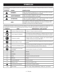
6 − Français Certains des symboles ci-dessous peuvent être utilisés sur l’outil. Veiller à les étudier et à apprendre leur signification. Une interprétation correcte de ces symboles permettra d’utiliser l’outil plus efficacement et de réduire les risques. SYMBOLE NOM DÉSIGNATION / EXPLICATION Symbol...
Page 40 - CARACTÉRISTIQUES ÉLECTRIQUES; DOUBLE ISOLATION; CONNEXIONS ÉLECTRIQUES; CORDONS PROLONGATEURS
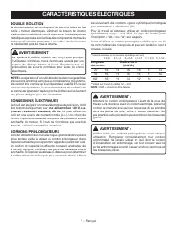
7 − Français CARACTÉRISTIQUES ÉLECTRIQUES DOUBLE ISOLATION La double isolation est un dispositif de sécurité utilisé sur les outils à moteur électriques, éliminant le besoin de cordon d’alimentation habituel à trois fils avec terre. Toutes les pièces métalliques exposées sont isolées des composants ...
Page 41 - GLOSSAIRE
8 − Français GLOSSAIRE Trou pilote (perceuses à colonne et scie à découper) Petit trou pratiqué dans une pièce servant de guide pour assurer la précision d’un trou de plus grand diamètre ou pour l’insertion d’une lame de scie à découper. Blocs poussoirs (pour dégauchisseuses/raboteuses) Dispositifs ...
Page 42 - CARACTÉRISTIQUES; FICHE TECHNIQUE
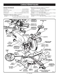
9 − Français CARACTÉRISTIQUES FICHE TECHNIQUE Trou d’axe ........................................................ 16 mm (5/8 po)Diamètre de la lame ........................................ 254 mm (10 po)Vitesse à vide ................................................4 600 / min (RPM)Alimentation........
Page 43 - BOUTON DE VERROUILLAGE DE BISEAU; MANETTE D’ENJAMBEMENT
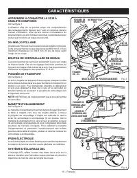
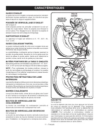
10 − Français CARACTÉRISTIQUES APPRENDRE À CONNAÎTRE LA SCIE À ONGLETS COMPOSÉS Voir la figure 1. L’utilisation sûre de ce produit exige une compréhension des renseignements figurant sur l’outil et contenus dans le manuel d’utilisation, ainsi qu’une bonne connaissance du projet entrepris. Avant d’ut...
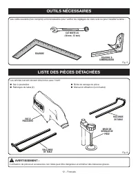
Page 45 - LISTE DES PIÈCES DÉTACHÉES; OUTILS NÉCESSAIRES
12 − Français LISTE DES PIÈCES DÉTACHÉES Fig. 6 Bride de serrage de pièce Manuel d’utilisation (non illustré) Sac à pouissière Rallonges de table (2) Les articles suivant doivent être inclus avec l’outil: AVERTISSEMENT : L’utilisation de pièces et accessoires non listés peut être dangereux e...
Page 46 - DÉBALLAGE; ASSEMBLAGE
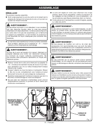
13 − Français DÉBALLAGE This product requires assembly. Sortir soigneusement la scie du carton en la tenant par la poignée de transport et la base de la scie, et la poser sur un plan de travail horizontal. AVERTISSEMENT : Ne pas utiliser le produit si, en le déballant, vous constatez que des éléme...
Page 48 - SAC À POUSSIÈRE
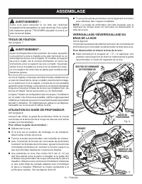
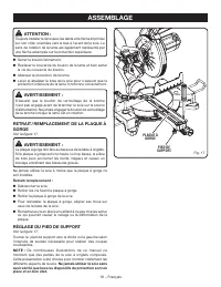
15 − Français Relâcher le guide et relever lentement le bras de la scie. Pour reverrouiller le bras de la scie : Tenir fermement la poignée en D et appuyer vers le bas en poussant simultanément la goupille de verrouillage à l’intérieur et vers le logement de la scie. Relâcher la goupille de ve...
Page 49 - RALLONGES DE TABLE
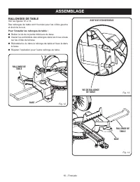
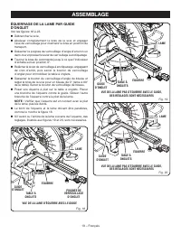
16 − Français RALLONGE DE TABLE Fig. 14 BASE ASSEMBLAGE RALLONGES DE TABLE Voir les figures 12 à 14. Des rallonges de table sont fournies pour les côtés gauche et droit de la scie. Pour l’installer les rallonges de table : Retirer le vis de la partie inférieure du base. Insérer les extrémités de...
Page 50 - INSTALLATION / REMPLACEMENT DE LA LAME
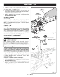
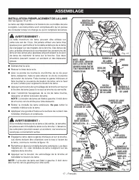
17 − Français ASSEMBLAGE INSTALLATION / REMPLACEMENT DE LA LAME Voir les figures 15 et 16. La lame est déjà installée à la livraison de ce modèle de scie à onglets. Les instructions sont comprises afin qu’on puisse les consulter lorsqu’on change ou qu’on remplace les lames. AVERTISSEMENT : La taille...
Page 51 - RÉGLAGE DU PIED DE SUPPORT; PLAQUE À
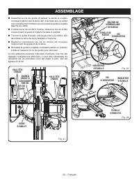
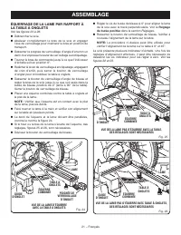
18 − Français ASSEMBLAGE ATTENTION : Toujours installer la lame avec les dents et la flèche imprimée sur son côté, orientées vers le bas à l’avant de la scie. Le sens de rotation de la lame est également représenté par une flèche estampée sur la protection supérieure. Serrer le boulon fermement. ...
Page 55 - UTILISATION
22 − Français AVERTISSEMENT : Pour éviter des blessures graves, toujours garder les mains hors de la zone dangereuse, c’est-à-dire à au moins 100 mm (4 po) de la lame. Ne jamais effectuer de coupes à main levée (c.-à-d. sans maintenir la pièce contre le guide). La lame pourrait se coincer dans la pi...
Page 57 - COUPE EN BISEAU; BRIDE DE
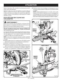
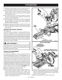
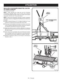
24 − Français UTILISATION Placer la pièce à couper à plat sur la table à onglet, l’un de ses bords solidement appuyé contre le guide. Si la planche est voilée, placer le côté convexe contre le guide. Si le bord concave d’une pièce est placé contre le guide, la pièce peut se refermer sur la lame en...
Page 58 - COUPE D’ONGLET COMPOSÉ
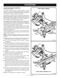
25 − Français UTILISATION COUPE D’ONGLET COMPOSÉ Voir les figures 31 et 32. Une coupe d’onglet composé consiste à utiliser un angle d’onglet et un angle de biseau simultanément. Ce type de coupe est utilisé pour la réalisation de cadres, de boîtes à pans inclinés et certains travaux de charpente. Po...
Page 59 - SUPPORT DE PIÈCES LONGUES
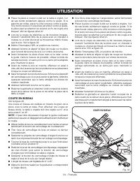
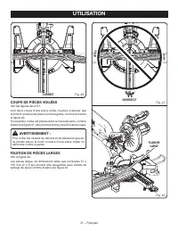
26 − Français UTILISATION Abaisser la lame et aligner la ligne de coupe sur la pièce avec le bord de la lame de scie ou l’ombre de la lame. Saisir fermement la pièce d’une main et la caler contre le guide. Dans la mesure du possible, utiliser la bride de serrage de pièce, un serre-joint ou ou au...
Page 60 - COMMENT FABRIQUER UNE GUIDE AUXILIAIRE
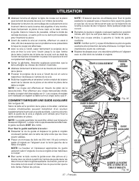
27 − Français COUPE À COULISSEMENT POUSSER VERS L’ARRIÈRE UTILISATION Abaisser la lame et aligner la ligne de coupe sur la pièce avec le bord de la lame de scie ou l’ombre de la lame. Desserrer le bouton de verrouillage de coulissement en le tournant dans le sens inverse des aiguilles d’une mont...
Page 61 - COUPE D’ONGLETS COMPOSÉS; ANGLE
28 − Français UTILISATION COUPE D’ONGLETS COMPOSÉS Le tableau des réglages d’angles ci-dessous est conçu pour faciliter les réglages. Les coupes composées étant les plus difficiles à réaliser, des essais doivent être effectués sur des chutes et la coupe définitive ne doit être effectuée qu’après mûr...
Page 62 - COUPE DE MOULURE COURONNÉE
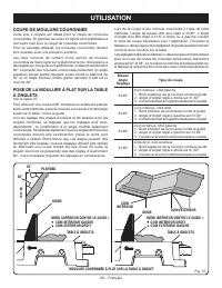
29 − Français UTILISATION Lors de la coupe d’une moulure couronnée à l’aide de cette méthode, l’angle de biseau doit être réglé à 33,85°. L’angle d’onglet doit être réglé à 31,6° à droite ou à gauche, suivant le sens de coupe nécessaire pour l’application. Consulter le tableau ci-dessous pour les ré...
Page 64 - COUPE DE PIÈCES VOILÉES; PLANCHE
31 − Français UTILISATION COUPE DE PIÈCES VOILÉES Voir les figures 40 et 41. Lors de la coupe d’une pièce voilée, toujours s’assurer que son bord convexe est placé contre le guide, comme le montre la figure 40. Si une pièce voilée est placée dans le mauvais sens, comme illustré à la figure 41, elle ...
Page 65 - RÉGLAGES; RÉGLAGE DU PIVOT DE BISEAU; RÉGLAGES DE BUTÉE POSITIVE
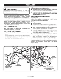
32 − Français AVERTISSEMENT : Avant d’effectuer tout réglage, s’assurer que l’outil est débranché. Le non respect de cet avertissement pourrait entraîner des blessures graves. La scie à onglets composés a été réglée en usine pour effectuer des coupes très précises. Toutefois, certains composants peu...
Page 66 - ENTRETIEN
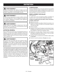
33 − Français AVERTISSEMENT : Utiliser exclusivement des pièces d’origine pour les réparations. L’usage de toute autre pièce pourrait créer une situation dangereuse ou endommager le produit. AVERTISSEMENT : Toujours porter une protection oculaire certifiée conforme à la norme ANSI Z87.1 lors de l’ut...
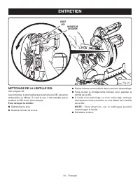
Page 67 - NETTOYAGE DE LA LENTILLE DEL; LENTE
34 − Français NETTOYAGE DE LA LENTILLE DEL Voir la figure 45. Avec le temps, il est possible que la lumière à la DEL devienne embrouillée ou diffuse. Si c’est le cas, il est possible que la lentille à la DEL doive être nettoyée. Pour nettoyer la lentille : Débrancher la scie. Soulever le bras de...
Page 68 - REGLAS DE SEGURIDAD GENERALES; ÁREA DE TRABAJO; SEGURIDAD ELÉCTRICA
2 − Español REGLAS DE SEGURIDAD GENERALES ADVERTENCIA: Lea todas las advertencias, instrucciones, ilustraciones y e s p e c i f i c a c i o n e s p ro p o rc i o n a d a s c o n e s t a herramienta eléctrica. No seguir las instrucciones indicadas a continuación puede provocar descargas eléctricas, i...
Page 69 - SERVICIO
3 − Español REGLAS DE SEGURIDAD GENERALES REGLAS DE SEGURIDAD SIERRA INGLETEADORA el trabajo, si además se maneja a la velocidad para la que está diseñada. No utilice la herramienta si el interruptor no enciende o no apaga. Cualquier herramienta eléctrica que no pueda controlarse con el interrupto...
Page 70 - REGLAS DE SEGURIDAD SIERRA INGLETEADORA; ADVERTENCIAS DE SEGURIDAD ADICIONALES
4 − Español REGLAS DE SEGURIDAD SIERRA INGLETEADORA No use la hoja hasta que la mesa esté libre de cualquier otra herramienta, desechos de madera, etc. Solo debe estar la pieza de trabajo. En caso de haber desechos pequeños, piezas de manera sueltas o cualquier otro objeto que haga contacto con la...
Page 72 - SÍMBOLOS; SÍMBOLO
6 − Español Es posible que se empleen en esta herramienta algunos de los siguientes símbolos. Le suplicamos estudiarlos y aprender su significado. Una correcta interpretación de estos símbolos le permitirá utilizar mejor y de manera más segura la herramienta. SÍMBOLO NOMBRE DENOMINACIÓN/EXPLICACIÓN ...
Page 73 - DOBLE AISLAMIENTO; CONEXIÓN ELÉCTRICA; CORDONES DE EXTENSIÓN; Longitud; ASPECTOS ELÉCTRICOS
7 − Español DOBLE AISLAMIENTO El doble aislamiento es una característica de seguridad de las herramientas eléctricas, la cual elimina la necesidad de usar el típico cordón eléctrico de tres conductores con conexión a tierra. Todas las partes metálicas expuestas están aisladas de los componentes metá...
Page 74 - GLOSARIO DE TÉRMINOS
8 − Español GLOSARIO DE TÉRMINOS Este es un corte en el cual la hoja no corta la pieza de trabajo en dos pedazos. Agujero guía (taladradoras de columna y sierras caladoras) Es un agujero pequeño taladrado en una pieza de trabajo, el cual sirve como guía para taladrar con precisión agujeros más grand...
Page 75 - CARACTERÍSTICAS; ESPECIFICACIONES DEL PRODUCTO
9 − Español CARACTERÍSTICAS ESPECIFICACIONES DEL PRODUCTO Orificio del eje .....................................................16 mm (5/8 pulg.)Diámetro de la hoja ........................................... 254 mm (10 pulg.)Velocidad en vacío .............................................. 4 600/mi...
Page 76 - PERILLA DE FIJACIÓN DE BISEL; CONTROL MANUAL DE RETENCIÓN
10 − Español CARACTERÍSTICAS FAMILIARÍCESE CON LA SIERRA INGLETEADORA COMPUESTA Vea la figura 1. El uso seguro que este producto requiere la comprensión de la información impresa en la herramienta y en el manual del operador así como ciertos conocimientos sobre el proyecto a realizar. Antes de usar ...
Page 77 - ESCALA DE INGLETES
11 − Español CARACTERÍSTICAS MANIJA DE FIJACIÓN DE INGLETE Vea la figura 3. La manija de fijación de inglete asegura firmemente la sierra en los ángulos de inglete deseados. Ajuste el mango para fijar la sierra en su lugar. Para liberar la sierra, afloje el mango y apriete la palanca de detención de...
Page 78 - LISTA DE PIEZAS SUELTAS; HERRAMIENTAS NECESARIAS
12 − Español LISTA DE PIEZAS SUELTAS Fig. 6 Prensa de trabajo Manual del operador (no se muestra) Saco captapolvo Extensiones de la mesa (2) Vienen incluidos los siguientes artículos con la herramienta: ADVERTENCIA: El empleo de aditamentos o accesorios no enumerados arriba podría ser peligr...
Page 79 - ARMADO; DESEMPAQUETADO
13 − Español ARMADO DESEMPAQUETADO Este producto requiere armarse. Levante cuidadosamente de la caja la sierra sujetándola del mango de acarreo y de la base, y colóquela sobre una superficie de trabajo a nivel. ADVERTENCIA: No utilice este producto si alguna pieza incluida en la Lista de piezas su...
Page 81 - SACO CAPTAPOLVO
15 − Español ARMADO Suelte la pasador de seguridad y levante lentamente el brazo de la sierra. Para volver a trabar el brazo de la sierra: Agarre firmemente el mango “D” y aplique presión hacia abajo mientras, al mismo tiempo, empuja el pasador de seguro hacia el alojamiento de la sierra. Libe...
Page 82 - EXTENSIONES DE LA MESA
16 − Español EXTENSIONES DE LA MESA Vea las figuras 12 a 14. Se proporcionan extensiones de la mesa para los lados izquierdo y derecho de la sierra. Para asegurar las extensiones de la mesa: Remueva el tornillo de la parte de abajo de la base. Inserte los extremos de la extensión dentro de los o...
Page 83 - PARA INSTALAR O REEMPLAZAR LA HOJA
17 − Español PARA INSTALAR O REEMPLAZAR LA HOJA Vea las figuras 15 y 16. La hoja viene instalada en este modelo de sierra ingleteadora. Para su referencia, se incluyen instrucciones para cambiar o reemplazar las hojas. ADVERTENCIA: La sierra tiene capacidad para hojas hasta de un diámetro de 10 pulg...
Page 84 - PLACA DE LA
18 − Español PRECAUCIÓN: Siempre instale la hoja con los dientes de la misma y la flecha impresa en el costado de la hoja apuntando hacia abajo en la parte frontal de la sierra. El sentido de giro de la hoja también está impreso en forma de flecha en la protección superior de la hoja. Apriete firm...
Page 85 - ESCUADRADO DE LA HOJA CON LA MESA
19 − Español Fig. 18 MANIJA DE FIJACIÓN DE INGLETE MESA DE INGLETES VISTA A DE LA HOJA A ESCUADRA CON LA GUÍA ESCUADRA GUÍA DE INGLETES HOJA ARMADO ESCUADRADO DE LA HOJA CON LA MESA DE INGLETES Vea las figuras 18 a 23. Desconecte la sierra. Tire del brazo de la sierra completamente hacia abajo y...
Page 88 - SISTEMA DE ILUMINACIÓN LED; FUNCIONAMIENTO
22 − Español ADVERTENCIA: No permita que su familarización con las herramientas lo vuelva descuidado. Tenga presente que un descuido de un instante es suficiente para causar una lesión grave. ADVERTENCIA: Siempre póngase protección ocular con la marca de cumplimiento de la norma ANSI Z87.1. Si no cu...
Page 89 - PARA REALIZAR CORTES NO DESLIZANTES
23 − Español PRENSA DE TRABAJO FUNCIONAMIENTO Baje el brazo de la sierra para que la hoja se encuentre aproximadamente a 6,35 mm (1/4 pulg.) de la pieza de trabajo. La sombra de la hoja se proyectará en la pieza de trabajo, indicando dónde hará contacto el diente de la hoja cuando se realice el cort...
Page 90 - PARA CORTAR A BISEL; CORTE EN BISEL; PRENSA DE
24 − Español Gire el brazo de control hasta no alinear el indicador con el ángulo deseado de la escala de ingletes. Suelte la palanca de detención de afloje, y luego ajuste la perilla de fijación de inglete para fijar la mesa de ingletes. NOTA: Puede ubicar rápidamente 0°, 15°, 22-1/2°, 31,6°, y...
Page 92 - PARA APOYAR LAS PIEZAS DE TRABAJO
26 − Español guía. Si se el canto cóncavo de la tabla se viniera sobre la hoja al final del corte, la atoraría. Vea las figuras 40 y 41. Al cortar tablas o molduras largas, apoye el extremo opuesto del material sobre un soporte de rodillo o con una superficie de trabajo a nivel con la mesa de la s...
Page 93 - FORMA DE HACER UNA GUÍA AUXILIAR
27 − Español en la parte trasera de la sierra, parando al alcanzar plenamente la posición posterior después de cada cada corte. Cuando la sierra este en marcha (encendida) NUNCA tire de la hoja de la sierra hacia usted ni hacia la parte delantera de la sierra. Suba el brazo de la sierra hasta su a...
Page 95 - CÓMO EFECTUAR CORTES A INGLETE COMBINADOS; INCLINACIÓN
29 − Español CÓMO EFECTUAR CORTES A INGLETE COMBINADOS Como ayuda para realizar los ajustes correctos, se suministra la siguiente tabla de ángulos combinados. Puesto que los cortes combinados son los más difíciles de obtener, deben efectuarse cortes de prueba en material de desecho, así como una gra...
Page 96 - CÓMO CORTAR MOLDURAS DE CORONA
30 − Español Al cortar molduras de corona con este método, el ángulo de bisel debe fijarse a 33,85°. El ángulo de inglete debe fijarse a 31,6°, a la derecha o izquierda, según el corte deseado para cada aplicación en particular. En la tabla mostrada a continuación encontrará los ajustes correctos de...
Page 98 - FORMA CORRECTA
32 − Español CÓMO CORTAR MATERIAL DISTORSIONADO Vea las figuras 40 y 41. Al cortar material distorsionado, siempre asegúrese de que esté colocado en la mesa de ingletes con el lado convexo contra la guía, como se muestra en la figura 40. Si se coloca de una forma equivocada el material distorsionado...
Page 99 - AJUSTES; AJUSTES DE LOS PIVOTES; AJUSTE DEL PIVOTE DE BISEL; AJUSTE DE LOS TOPES
33 − Español AJUSTES ADVERTENCIA: Antes de efectuar cualquier ajuste, asegúrese de que la herramienta esté desconectada del suministro de corriente. La inobservancia de esta advertencia podría causar lesiones corporales serias. La sierra ingleteadora combinada ha sido ajustada en la fábrica para pro...
Page 100 - MANTENIMIENTO; REEMPLAZO DE LAS ESCOBILLAS
34 − Español ADVERTENCIA: Al dar servicio a la unidad, utilice sólo piezas de repuesto idénticas. El empleo de piezas diferentes puede presentar un peligro o causar daños al producto. ADVERTENCIA: Siempre póngase protección ocular con la marca de cumplimiento de la norma ANSI Z87.1. Si la operación ...
Page 101 - LIMPIEZA DE LA LENTE LED
35 − Español MANTENIMIENTO LIMPIEZA DE LA LENTE LED Vea la figura 45. Con el tiempo, es posible que la luz LED se vea opacada o tenue. Si ocurre esto, es posible que la lente LED deba limpiarse. Para limpiar la lente: Desconecte la sierra. Eleve el brazo de la sierra. Vuelve a colocar la hoja....
Page 104 - OPERATOR’S MANUAL; MANUEL D’UTILISATION / MANUAL DEL OPERADOR; SLIDING COMPOUND MITER SAW WITH LED; SCIE À ONGLETS COMBINÉS COULISSANTE AVEC DEL /
99500065212-7-18 (REV:03) OPERATOR’S MANUAL MANUEL D’UTILISATION / MANUAL DEL OPERADOR SLIDING COMPOUND MITER SAW WITH LED SCIE À ONGLETS COMBINÉS COULISSANTE AVEC DEL / SIERRA INGLETEADORA COMPUESTA DESLIZANTE CON LED TSS103/TSS103T ONE WORLD TECHNOLOGIES, INC. P.O. Box 1288, Anderson, SC 29622 • P...


 Ryobi P553
User Manual
Ryobi P553
User Manual
 Ryobi P553-PSK005
User Manual
Ryobi P553-PSK005
User Manual
 Ryobi P553-PSK006
User Manual
Ryobi P553-PSK006
User Manual
 Ryobi PBLMS01B
User Manual
Ryobi PBLMS01B
User Manual
 Ryobi PBLMS01K
User Manual
Ryobi PBLMS01K
User Manual
 Ryobi PBLMS01K-A18MS01G
User Manual
Ryobi PBLMS01K-A18MS01G
User Manual
 Ryobi PBLMS01K-PBP004
User Manual
Ryobi PBLMS01K-PBP004
User Manual
 Ryobi PBT01B
User Manual
Ryobi PBT01B
User Manual
 Ryobi PBT01B-A067101
User Manual
Ryobi PBT01B-A067101
User Manual
 Ryobi PBT01B-A18MS01G
User Manual
Ryobi PBT01B-A18MS01G
User Manual
 Ryobi PBT01B-PBP004
User Manual
Ryobi PBT01B-PBP004
User Manual
 Ryobi PBT01B-PCL204HPK
User Manual
Ryobi PBT01B-PCL204HPK
User Manual
 Ryobi PBT01B-PSK005
User Manual
Ryobi PBT01B-PSK005
User Manual
 Ryobi TS1144
User Manual
Ryobi TS1144
User Manual
 Ryobi TS1144-A18MS01G
User Manual
Ryobi TS1144-A18MS01G
User Manual
 Ryobi TS1346
User Manual
Ryobi TS1346
User Manual
 Ryobi TSS103
User Manual
Ryobi TSS103
User Manual
 Ryobi TSS103-A181001
User Manual
Ryobi TSS103-A181001
User Manual
 Ryobi TSS103-A181002
User Manual
Ryobi TSS103-A181002
User Manual
 Ryobi TSS103-A18MS01G
User Manual
Ryobi TSS103-A18MS01G
User Manual