Page 2 - READ ALL INSTRUCTIONS; GENERAL SAFETY RULES
2 − English WARNING: Read all safety warnings and all instructions. Failure to follow the warnings and instructions may result in electric shock, fire and/or serious injury. READ ALL INSTRUCTIONS KNOW YOUR POWER TOOL. Read the operator’s manual carefully. Learn the applications and limitations as ...
Page 4 - SPECIFIC SAFETY RULES
4 − English SPECIFIC SAFETY RULES NEVER reach to pick up a workpiece, a piece of scrap, or anything else that is in or near the cutting path of the blade. NEVER move the workpiece or make adjustment to any cutting angle while the saw is running and the blade is rotating. Any slip can result in c...
Page 5 - SYMBOLS; SYMBOL
5 − English SYMBOLS Some of the following symbols may be used on this tool. Please study them and learn their meaning. Proper interpretation of these symbols will allow you to operate the tool better and safer. Safety Alert Indicates a potential personal injury hazard. Read Operator’s Manual To redu...
Page 6 - ELECTRICAL; DOUBLE INSULATION; ELECTRICAL CONNECTION; power supply that is 120 V, AC only (normal; EXTENSION CORDS; Cord Length; CALIFORNIA PROPOSITION 65
6 − English ELECTRICAL DOUBLE INSULATION Double insulation is a concept in safety in electric power tools, which eliminates the need for the usual three-wire grounded power cord. All exposed metal parts are isolated from the internal metal motor components with protecting insulation. Double insulate...
Page 7 - GLOSSARY OF TERMS
7 − English GLOSSARY OF TERMS Push Blocks (for jointer planers) Device used to feed the workpiece over the jointer planer cutterhead during any operation. This aid helps keep the operator’s hands well away from the cutterhead. Push Blocks (for table saws) Device used to hold the workpiece during cut...
Page 8 - FEATURES; PRODUCT SPECIFICATIONS; DEPTH
8 − English FEATURES PRODUCT SPECIFICATIONS Arbor Hole ............................................................... 5/8 in.Blade Diameter ..........................................................10 in.No Load Speed ................................... 4,800 r/min. (RPM)Input ........................
Page 11 - LOOSE PARTS LIST; TOOLS NEEDED
11 − English LOOSE PARTS LIST Fig. 6 Work Clamp Operator’s Manual Dust Bag Table Extensions (2) WORK CLAMP DUST BAG TABLE EXTENSION TABLE EXTENSION The following items are included with the tool: WARNING: The use of attachments or accessories not listed might be hazardous and could cause ser...
Page 12 - ASSEMBLY; UNPACKING
12 − English ASSEMBLY UNPACKING This product requires assembly. Carefully lift saw from the carton by the carrying handle and the saw base, and place it on a level work surface. WARNING: Do not use this product if any parts on the Loose Parts List are already assembled to your product when you unp...
Page 13 - MOUNTING HOLES; To use the depth stop:; LOCKING / UNLOCKING THE SAW ARM; LOCK
13 − English Fig. 9 ASSEMBLY MOUNTING HOLES See Figure 7. WARNING: Before starting any cutting operation, clamp or bolt your miter saw to a workbench or an approved miter saw stand. If a miter saw stand is used, read operator’s manual and follow the instructions for the miter saw stand. Never operat...
Page 14 - DUST BAG; To install the work clamp:
14 − English ASSEMBLY DUST BAG See Figure 10. A dust bag is provided for use on this miter saw. It fits over the exhaust port on the back of the saw. NOTE: The exhaust port also accepts 1-1/4 in. vacuum hose. BLADE WRENCH See Figure 11. A blade wrench is included with this saw. One end of the wrench...
Page 15 - TABLE EXTENSIONS; To install table extensions:
15 − English ASSEMBLY TABLE EXTENSIONS See Figures 12 - 14. Table extensions have been provided for both the left and the right side of the saw. To install table extensions: Remove the screw from the end of the table extension. Insert the ends of extension into the holes in the sides of the base...
Page 16 - TO INSTALL / REPLACE THE BLADE; Do not
16 − English ASSEMBLY TO INSTALL / REPLACE THE BLADE See Figures 15 - 16. WARNING: A 10 in. blade is the maximum blade capacity of the saw. Never use a blade that is too thick to allow outer blade washer to engage with the flats on the spindle. Larger blades will come in contact with the blade guard...
Page 17 - ALIGNING THE LASER GUIDE LINE; RED
17 − English ASSEMBLY Tighten blade bolt securely. Replace the lower blade guard and blade bolt cover. Securely tighten the blade bolt cover screw. Raise and lower the saw head and ensure that the lower blade guard operates properly. WARNING: Make sure the spindle lock button is not engaged ...
Page 18 - REMOVING / REPLACING THE THROAT PLATE
18 − English ASSEMBLY REMOVING / REPLACING THE THROAT PLATE See Figure 18. WARNING: The throat plate must be below the miter table. If the throat plate is too high or too low, the workpiece can catch on the uneven edges resulting in binding which could result in serious personal injury. Never operat...
Page 19 - BEVEL
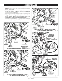
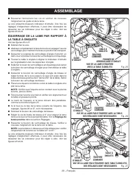
19 − English ASSEMBLY If the front or back edge of the saw blade angles away from the square as shown in figures 21 - 22, adjustments are needed. Using the blade wrench provided, loosen the socket head screws that secure the miter fence to the miter table. Rotate the miter fence left or right ...
Page 20 - SQUARING THE BLADE TO THE MITER TABLE; Positive Stop
20 − English ASSEMBLY Your saw has several scale indicators. After squaring adjustments have been made, it may be necessary to loosen the indicator screws and reset them to zero. See Figures 23 - 24. SQUARING THE BLADE TO THE MITER TABLE See Figures 25 - 27. Unplug the saw. Pull the saw arm all ...
Page 21 - OPERATION; APPLICATIONS; CUTTING WITH YOUR COMPOUND MITER SAW
21 − English OPERATION WARNING: Do not allow familiarity with tools to make you careless. Remember that a careless fraction of a second is sufficient to inflict serious injury. WARNING: Always wear eye protection with side shields marked to comply with ANSI Z87.1. Failure to do so could result in ob...
Page 22 - MITER CUT; CROSS CUT
22 − English TO MAKE NON-SLIDING CUTS WARNING: Securely tighten the slide lock knob when making any non-sliding cuts. Failure to tighten the knob could result in the saw head moving during the cutting operation. TO MITER CUT / CROSS CUT See Figures 28 - 29. A cross cut is made by cutting across the ...
Page 23 - TO BEVEL CUT
23 − English OPERATION Grasp the saw handle firmly. Squeeze the switch trigger. Allow several seconds for the blade to reach maximum speed. Slowly lower the blade into and through the workpiece. Release the switch trigger and allow the saw blade to stop rotating before raising the blade out of...
Page 24 - TO COMPOUND MITER CUT; COMPOUND MITER CUT
24 − English OPERATION TO COMPOUND MITER CUT See Figures 31 - 32. A compound miter cut is a cut made using a miter angle and a bevel angle at the same time. This type of cut is used to make picture frames, cut molding, make boxes with sloping sides, and for certain roof framing cuts. To make this ty...
Page 25 - TO SUPPORT LONG WORKPIECES; NEVER
25 − English OPERATION Grasp the stock firmly with one hand and secure it against the fence. Use the optional work clamp or a C-clamp to secure the workpiece when possible. Before turning on the saw, perform a dry run of the cutting operation just to make sure that no problems will occur when th...
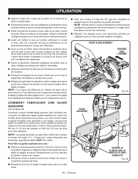
Page 26 - MAKING AN AUXILIARY FENCE; MUST
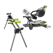
26 − English OPERATION When cutting long pieces of lumber or molding, support the opposite end of the stock with a roller stand or with a work surface level with the saw table. See Figure 33. Align the cutting line on the workpiece with the edge of saw blade or laser line. L o o s e n t h e s ...
Page 27 - PITCH; CUTTING COMPOUND MITERS
27 − English OPERATION 4 PITCH OF SIDE NUMBER OF SIDES 0° 6 M- 45.00°B- 0.00° 5° 10° 15° 20° 25° 30° 35° 40° 45° 50° 55° 60° 65° 70° 75° 80° 85° 90° 5 7 8 9 10 M- 36.00°B- 0.00° M- 30.00°B- 0.00° M- 25.71°B- 0.00° M- 22.50°B- 0.00° M- 20.00°B- 0.00° M- 18.00°B- 0.00° Each B (Bevel) and M (Miter) Set...
Page 28 - CUTTING CROWN MOLDING; Bevel
28 − English OPERATION Fig. 37 When cutting crown molding by this method, the bevel angle should be set at 33.85 ° . The miter angle should be set at 31.6 ° either right or left, depending on the desired cut for the application. See the chart below for correct angle settings and correct positioning ...
Page 30 - CUTTING WARPED MATERIAL; RIGHT
30 − English OPERATION CUTTING WARPED MATERIAL See Figures 40 - 41. When cutting warped material, always make sure it is positioned on the miter table with the convex side against the fence as shown in figure 40. If the warped material is positioned the wrong way as shown in figure 41, it will pinch...
Page 31 - ADJUSTMENTS; PIVOT ADJUSTMENTS; AUTHORIZED SERVICE CENTER.; TO ADJUST THE BEVEL PIVOT; AUTHORIZED SERVICE; POSITIVE STOP ADJUSTMENTS
31 − English POSITIVE STOP ADJUSTMENT SCREW FOR 45 ° ANGLES ADJUSTMENTS WARNING: Before performing any adjustment, make sure the tool is unplugged from the power supply. Failure to heed this warning could result in serious personal injury. The compound miter saw has been adjusted at the factory for ...
Page 32 - TO ADJUST THE LASER GUIDE; AUTHORIZED SERVICE CENTER
32 − English ADJUSTMENTS DANGER: Laser radiation. Avoid direct eye contact with light source. WARNING: Use of controls or adjustments or performance of procedures other than those specified herein can result in hazardous radiation exposure. TO ADJUST THE LASER GUIDE See Figure 44. Set miter and be...
Page 33 - MAINTENANCE; GENERAL MAINTENANCE; Proceed as follows when replacement is required:; This product has a Three-year Limited Warranty.
33 − English MAINTENANCE WARNING: When servicing, use only identical replacement parts. Use of any other part can create a hazard or cause product damage. WARNING: Always wear eye protection with side shields marked to comply with ANSI Z87.1 during product operation. If operation is dusty, also wear...
Page 34 - LIRE TOUTES LES INSTRUCTIONS; RÈGLES DE SÉCURITÉ GÉNÉRALES
2 − Français AVERTISSEMENT : Lire attentivement toutes les instructions. Le non respect de toutes les instructions ci-dessous peut entraîner un choc électrique, un incendie et / ou des blessures graves. LIRE TOUTES LES INSTRUCTIONS VEILLER À BIEN CONNAÎTRE L’OUTIL. Lire attentivement le manuel d’u...
Page 35 - RÈGLES DE SÉCURITÉ PARTICULIÈRES
3 − Français RÈGLES DE SÉCURITÉ GÉNÉRALES NE PAS MALTRAITER LE CORDON D’ALIMENTATION. Ne jamais utiliser le cordon d’alimentation pour transporter l’outil et ne jamais débrancher ce dernier en tirant sur le cordon. Garder le cordon à l’écart de la chaleur, de l’huile et des objets tranchants. N’...
Page 37 - SYMBOLES
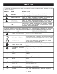
5 − Français SYMBOLES Certains des symboles ci-dessous peuvent être utilisés sur l’outil. Veiller à les étudier et à apprendre leur signification. Une interprétation correcte de ces symboles permettra d’utiliser l’outil plus efficacement et de réduire les risques. Symbole d’alerte de sécurité Indiqu...
Page 38 - CARACTÉRISTIQUES ÉLECTRIQUES; DOUBLE ISOLATION; une alimentation 120 V,; CORDONS PROLONGATEURS; Longueur; PROPOSITION 65 DE L’ÉTAT DE CALIFORNIE
6 − Français CARACTÉRISTIQUES ÉLECTRIQUES DOUBLE ISOLATION La double isolation est un dispositif de sécurité utilisé sur les outils à moteur électriques, éliminant le besoin de cordon d’alimentation habituel à trois fils avec terre. Toutes les pièces métalliques exposées sont isolées des composants ...
Page 39 - GLOSSAIRE
7 − Français GLOSSAIRE Blocs poussoirs (pour dégauchisseuses/raboteuses) Dispositif utilisés pour pousser le matériau contre la tête de coupe lors de toute opération. Ce dispositif aide à tenir la main de l’opérateur bien à l’écart de la lame. Blocs poussoirs (pour scies à table) Dispositifs utilisé...
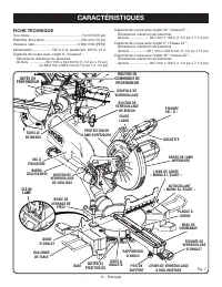
Page 40 - CARACTÉRISTIQUES; FICHE TECHNIQUE; BOUTON DE; CLÉ DE; BUTÉE DE
8 − Français CARACTÉRISTIQUES FICHE TECHNIQUE Trou d’axe .......................................................16 mm (5/8 po)Diamètre de la lame....................................... 254 mm (10 po)Vitesse à vide ............................................ 4 800 r/min (RPM)Alimentation...............
Page 43 - LISTE DES PIÈCES DÉTACHÉES; OUTILS NÉCESSAIRES
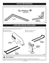
11 − Français LISTE DES PIÈCES DÉTACHÉES Fig. 6 Bride de serrage de pièce Manuel d’utilisation Sac à pouissière Rallonges de table (2) Les articles suivant doivent être inclus avec l’outil: AVERTISSEMENT : L’utilisation de pièces et accessoires non listés peut être dangereux et entraîner des...
Page 44 - ASSEMBLAGE; DÉBALLAGE
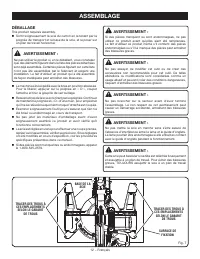
12 − Français ASSEMBLAGE DÉBALLAGE This product requires assembly. Sortir soigneusement la scie du carton en la tenant par la poignée de transport et la base de la scie, et la poser sur un plan de travail horizontal. AVERTISSEMENT : Ne pas utiliser le produit si, en le déballant, vous constatez qu...
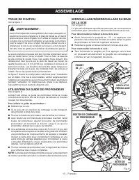
Page 45 - TROUS DE FIXATION; VERROUILLAGE/DÉVERROUILLAGE DU BRAS; POIGNÉE; BOUTON DE COMMANDE
13 − Français ASSEMBLAGE TROUS DE FIXATION Voir la figure 7. AVERTISSEMENT : Avant d’entreprendre toute opération de coupe, assujettir ou boulonner la scie à onglets sur le plan de travail ou un stand approuvé pour scie à onglets. Si on utilise un support de scie à onglet, lire le manuel d’utilisati...
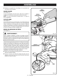
Page 46 - GUIDE SCIURE
14 − Français ASSEMBLAGE Relâcher la goupille de verrouillage et lui permettre de verrouiller la scie en place. GUIDE SCIURE Voir la figure 10. Un sac à poussières est fourni avec cette scie à onglets. Il s’adapte sur l’orifice de sortie situé à l’arrière de la scie. NOTE : Le orifice d’évacuation...
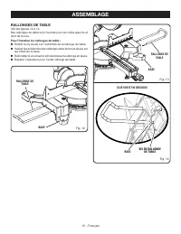
Page 47 - RALLONGES DE TABLE; VIS DE RALLONGE
15 − Français ASSEMBLAGE RALLONGES DE TABLE Voir les figures 12 à 14. Des rallonges de table sont fournies pour les côtés gauche et droit de la scie. Pour l’installer les rallonges de table : Retirer la vis située sur l’extrémité de la rallonge de table. Insérer les extrémités des rallonges dans...
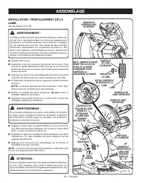
Page 48 - INSTALLATION / REMPLACEMENT DE LA
16 − Français ASSEMBLAGE INSTALLATION / REMPLACEMENT DE LA LAME Voir les figures 15 et 16. AVERTISSEMENT : La taille maximum de lame pouvant être utilisée sur cette scie est de 10 po. Ne jamais utiliser une lame trop épaisse pour permettre à la rondelle extérieure de la lame de s’engager sur les mép...
Page 49 - ALIGNEMENT DU TRAIT LASER
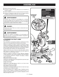
17 − Français ASSEMBLAGE Serrer le boulon fermement. Remettre la garde de lame inférieure et le couvercle du boulon en place. Serrer solidement le vis du couvercle de boulon de la lame. Soulever et abaisser la tête de la scie et s’assurer que le protège-lame inférieur fonctionne correctement...
Page 50 - RÉGLAGE DU PIED DE SUPPORT
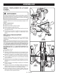
18 − Français ASSEMBLAGE RETRAIT / REMPLACEMENT DE LA PLAQUE À GORGE Voir la figure 18. AVERTISSEMENT : La plaque à gorge doit être au dessous de la table à onglets. Si la plaque à gorge est trop haute ou trop basse, la pièce de bois peut accrocher les bords inégaux et causer un blocage entraînant d...
Page 53 - UTILISATION
21 − Français UTILISATION AVERTISSEMENT : Ne pas laisser la familiarité avec l’outil faire oublier la prudence. Ne pas oublier qu’une fraction de seconde d’inattention peut entraîner des blessures graves. AVERTISSEMENT : Toujours porter une protection oculaire certifiée conforme à la norme ANSI Z87....
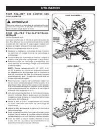
Page 54 - P O U R C O U P E S D ’ O N G L E T S / T R A N S -
22 − Français BRIDE DE SERRAGE DE PIÈCE P O U R R É A L I S E R D E S C O U P E S N O N COULISSANTES AVERTISSEMENT : Bien serrer le bouton de verrouillage du coulissement lors de coupes non coulissantes. Si le bouton est mal serré, la tête de la scie peut bouger durant la coupe. P O U R C O U P E S ...
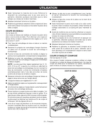
Page 55 - COUPE EN BISEAU; COUPE D’ONGLET COMPOSÉ; BRIDE DE
23 − Français UTILISATION Saisir fermement le manche de la scie. Enfoncer le dispositif de verrouillage avec le po puis serrer la gâchette. Attendre quelques secondes que la lame atteigne sa vitesse de rotation maximale. Abaisser lentement la lame sur la pièce. Relâcher la gâchette et attendre...
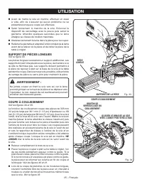
Page 57 - SUPPORT DE PIÈCES LONGUES; NE
25 − Français UTILISATION Avant de mettre la scie en marche, effectuer un essai à vide, afin de s’assurer qu’aucun problème ne se présentera lorsque la coupe est effectuée. Saisir fermement le manche de la scie. Enfoncer le dispositif de verrouillage avec le pouce puis serrer la gâchette. Attend...
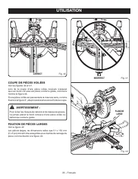
Page 58 - DOIT
26 − Français UTILISATION Aligner la ligne de coupe de la pièce sur le bord de la lame ou ligne laser. Desserrer le bouton de verrouillage de coulissement en le tournant dans le sens inverse des aiguilles d’une montre. Saisir fermement la pièce d’une main et la caler contre le guide. Dans la m...
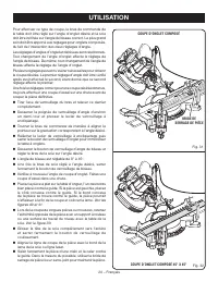
Page 59 - ANGLE; COUPE D’ONGLETS COMPOSÉS
27 − Français UTILISATION 4 ANGLE DE CÔTÉ NOMBRE DE CÔTÉS 0° 6 5° 10° 15° 20° 25° 30° 35° 40° 45° 50° 55° 60° 65° 70° 75° 80° 85° 90° 5 7 8 9 10 Chaque angle B (biseau) et M (onglet) est indiquée au 0,005 ème de degré le plus proche. RÉGLAGES D’ANGLES COMPOSÉS POUR LES CONSTRUCTIONS COURANTES COUPE ...
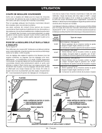
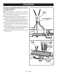
Page 60 - COUPE DE MOULURE COURONNÉE
28 − Français UTILISATION Lors de la coupe d’une moulure couronnée à l’aide de cette méthode, l’angle de biseau doit être réglé à 33,85°. L’angle d’onglet doit être réglé à 31,6° à droite ou à gauche, suivant le sens de coupe nécessaire pour l’application. Consulter le tableau ci-dessous pour les ré...
Page 62 - COUPE DE PIÈCES VOILÉES; PLANCHE
30 − Français UTILISATION COUPE DE PIÈCES VOILÉES Voir les figures 40 et 41. Lors de la coupe d’une pièce voilée, toujours s’assurer que son bord convexe est placé contre le guide, comme le montre la figure 40. Si une pièce voilée est placée dans le mauvais sens, comme illustré à la figure 41, elle ...
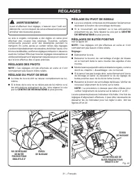
Page 63 - RÉGLAGES; RÉGLAGES DES PIVOTS; CENTRE DE RÉPARATIONS; RÉGLAGE DU PIVOT DE BISEAU; CENTRE; RÉGLAGES DE BUTÉE POSITIVE
31 − Français VIS DE RÉGLAGE DE BUTÉE POSITIVE POUR ONGLETS À 45° RÉGLAGES AVERTISSEMENT : Avant d’effectuer tout réglage, s’assurer que l’outil est débranché. Le non respect de cet avertissement pourrait entraîner des blessures graves. La scie à onglets composés a été réglée en usine pour effectuer...
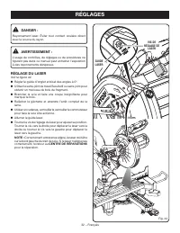
Page 64 - RÉGLAGE DU LASER
32 − Français RÉGLAGES DANGER : Rayonnement laser. Éviter tout contact oculaire direct avec la source du rayon. AVERTISSEMENT : L’usage de contrôles, de réglages ou de procédures ne figurant pas dans ce manuel peut entraîner l’exposition à des rayonnements dangereux. RÉGLAGE DU LASER Voir la figure ...
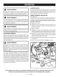
Page 65 - ENTRETIEN; ENTRETIEN GÉNÉRAL
33 − Français ENTRETIEN AVERTISSEMENT : Utiliser exclusivement des pièces d’origine pour les réparations. L’usage de toute autre pièce pourrait créer une situation dangereuse ou endommager le produit. AVERTISSEMENT : Toujours porter une protection oculaire certifiée conforme à la norme ANSI Z87.1 lo...
Page 66 - REGLAS DE SEGURIDAD GENERALES; Lea y comprenda todas las instrucciones.; LEA TODAS LAS INSTRUCCIONES
2 − Español REGLAS DE SEGURIDAD GENERALES ADVERTENCIA: Lea y comprenda todas las instrucciones. El incumplimiento de las instrucciones señaladas abajo puede causar descargas eléctricas, incendios y lesiones serias. LEA TODAS LAS INSTRUCCIONES FAMILIARÍCESE CON SU HERRAMIENTA ELÉCTRICA. Lea cuidado...
Page 68 - REGLAS DE SEGURIDAD ESPECÍFICAS
4 − Español REGLAS DE SEGURIDAD ESPECÍFICAS desperdicio de una pieza de trabajo en cualquier operación. Si se utilizan juntos una prensa para pieza de trabajo y un tope de longitud, ambos deben estar instalados en el mismo lado de la mesa de la sierra para evitar que la sierra coja el extremo suelto...
Page 69 - SÍMBOLOS; SÍMBOLO
5 − Español SÍMBOLOS Es posible que se empleen en esta herramienta algunos de los siguientes símbolos. Le suplicamos estudiarlos y aprender su significado. Una correcta interpretación de estos símbolos le permitirá utilizar mejor y de manera más segura la herramienta. Alerta de seguridad Indica un p...
Page 70 - ASPECTOS ELÉCTRICOS; DOBLE AISLAMIENTO; un suministro; CORDONES DE EXTENSIÓN; Longitud
6 − Español ASPECTOS ELÉCTRICOS DOBLE AISLAMIENTO El doble aislamiento es una característica de seguridad de las herramientas eléctricas, la cual elimina la necesidad de usar el típico cordón eléctrico de tres conductores con conexión a tierra. Todas las partes metálicas expuestas están aisladas de ...
Page 71 - GLOSARIO DE TÉRMINOS
7 − Español GLOSARIO DE TÉRMINOS Bloques empujadores (para cepillos de juntas) Son dispositivos empleados para avanzar la pieza de trabajo por el cepillo de juntas durante cualquier operación. Este medio ayuda al operador a mantener las manos alejadas de la cabeza de corte.Bloques empujadores (para ...
Page 72 - CARACTERÍSTICAS; ESPECIFICACIONES DEL PRODUCTO; PERILLA DE; LLAVE; TOPE DE
8 − Español CARACTERÍSTICAS ESPECIFICACIONES DEL PRODUCTO Orificio del eje ..................................................16 mm (5/8 pulg.)Diámetro de la hoja ........................................254 mm (10 pulg.)Velocidad en vacío .........................................4 800 r/min (RPM)Corr...
Page 73 - MOTOR DE 15 AMPERES
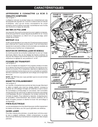
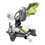
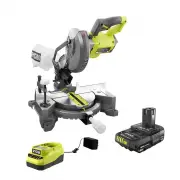
9 − Español CARACTERÍSTICAS F A M I L I A R Í C E S E C O N L A S I E R R A INGLETEADORA COMPUESTA Vea la figura 1. El uso seguro que este producto requiere la comprensión de la información impresa en la herramienta y en el manual del operador así como ciertos conocimientos sobre el proyecto a reali...
Page 74 - GUÍA LÁSER; PROTECCIÓN INFERIOR RETRÁCTIL DE LA
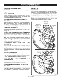
10 − Español CARACTERÍSTICAS GUÍA LÁSER Para cortes más precisos, se incluye una guía láser con la sierra ingleteadora. Cuando se usa correctamente la guía láser, sirve para efectuar cortes de precisión con mayor facilidad. INTERRUPTOR EL LÁSER Vea la figura 2. Utilice el interruptor el láser para e...
Page 75 - LISTA DE PIEZAS SUELTAS; HERRAMIENTAS NECESARIAS
11 − Español LISTA DE PIEZAS SUELTAS Fig. 6 Prensa de trabajo Manual del operador Saco captapolvo Extensiones de la mesa (2) Vienen incluidos los siguientes artículos con la herramienta: ADVERTENCIA: El empleo de aditamentos o accesorios no enumerados arriba podría ser peligros y causar lesi...
Page 76 - ARMADO; DESEMPAQUETADO
12 − Español ARMADO DESEMPAQUETADO Este producto requiere armarse. Levante cuidadosamente de la caja la sierra sujetándola del mango de acarreo y de la base, y colóquela sobre una superficie de trabajo a nivel. ADVERTENCIA: No utilice este producto si alguna pieza incluida en la lista de piezas su...
Page 77 - AGUJEROS DE MONTAJE; PROCEDIMIENTO DE TRABA Y DESTRABA EL; MANGO
13 − Español ARMADO AGUJEROS DE MONTAJE Vea la figura 7. ADVERTENCIA: Antes de iniciar cualquier operación de corte, sujete con prensa(s) o atornille la sierra ingleteadora al banco de trabajo o pedestal para sierra ingleteadora aprobado. Si se utiliza un pedestal para sierra ingleteadora, lea el ma...
Page 78 - SACO CAPTAPOLVO; LLAVE DE LA HOJA
14 − Español ARMADO SACO CAPTAPOLVO Vea la figura 10. Se suministra un saco captapolvo para utilizarse con la sierra ingleteadora. Se acopla en la abertura de salida del aserrín, en la parte posterior de la sierra. NOTA: El orificio de escape acepta también 1-1/4 en. saco captapolvo. LLAVE DE LA HOJ...
Page 79 - EXTENSIONES DE LA MESA
15 − Español ARMADO EXTENSIONES DE LA MESA Vea las figuras 12 a 14. Se proporcionan extensiones de la mesa para los lados izquierdo y derecho de la sierra. Para asegurar las extensiones de la mesa: Retire el tornillo del extremo de la extensión de la mesa. Inserte los extremos de la extensión de...
Page 80 - PARA INSTALAR O REEMPLAZAR LA HOJA
16 − Español ARMADO PARA INSTALAR O REEMPLAZAR LA HOJA Vea las figuras 15 y 16. ADVERTENCIA: La sierra tiene capacidad para hojas hasta de un diámetro de 10 pulg. Nunca utilice una hoja tan gruesa que la arandela exterior de la hoja no se enganche en las partes planas del husillo. Las hojas más gran...
Page 81 - ALINEACIÓN DE LA LÍNEA DE LA GUÍA LÁSER; LÍNEA ROJA; INTERRUPTOR
17 − Español ARMADO Apriete firmemente el perno de la hoja. Vuelva a colocar la protección inferior y la tapa del perno de la hoja. Aprieta firmemente el tornillo de la cubierta de la hoja. Levante y baje el cabezal de la sierra y asegúrese de que el protector de la hoja inferior funcione co...
Page 82 - PARA AJUSTAR PIED DE SUPPORT
18 − Español ARMADO EXTRACCIÓN / REEMPLAZO DE LA PLACA DE GARGANTA Vea la figura 18. ADVERTENCIA: La placa de la garganta debe estar a debajo de la mesa de ingletes. Si la placa de la garganta está demasiado alta o demasiado baja, la pieza de trabajo puede engancharse en los bordes desiguales y resu...
Page 85 - FUNCIONAMIENTO
21 − Español FUNCIONAMIENTO ADVERTENCIA: No permita que su familarización con las herramientas lo vuelva descuidado. Tenga presente que un descuido de un instante es suficiente para causar una lesión grave. ADVERTENCIA: Siempre póngase protección ocular con la marca de cumplimiento de la norma ANSI ...
Page 87 - PARA CORTAR A BISEL; CORTE EN BISEL; PARA EFECTUAR UN CORTE A INGLETE; PRENSA DE
23 − Español FUNCIONAMIENTO PARA CORTAR A BISEL Vea la figura 30. Un corte en bisel se efectúa cortando a través de la fibra de la pieza de trabajo con la hoja en ángulo con dicha pieza. Un corte en bisel recto se efectúa con la mesa de ingletes en la posición de cero grados y la hoja a un ángulo en...
Page 88 - CORTE EN BISEL COMBINADO
24 − Español FUNCIONAMIENTO Para efectuar este tipo de corte, el brazo de control de la mesa de ingletes debe girarse al ángulo correcto y el brazo de la sierra debe inclinarse al ángulo de bisel correcto. Siempre debe tenerse cuidado al preparar la unidad para cortes a inglete combinados debido a l...
Page 89 - PARA APOYAR LAS PIEZAS DE TRABAJO
25 − Español FUNCIONAMIENTO Baje lentamente la hoja de la sierra hacia la pieza de trabajo y corte ésta. Suelte el gatillo del interruptor y permita que se cese de girar la hoja de la sierra antes de levantarla de la pieza de trabajo. Espere hasta que el freno eléctrico detenga la hoja antes de ...
Page 90 - FORMA DE HACER UNA GUÍA AUXILIAR
26 − Español FUNCIONAMIENTO Afloje la perilla de fijación de la corredera girándola en sentido antihorario. Sujete firmemente la pieza con una mano y asegúrela contra la guía. Use la prensa de trabajo o una prensa de mano para asegurar la pieza de trabajo siempre que sea posible. Antes de ence...
Page 91 - AJUSTES DE ÁNGULOS COMBINADOS PARA ESTRUCTURAS COMUNES; CÓMO EFECTUAR CORTES A INGLETE COMBINADOS; INCLINACIÓN
27 − Español FUNCIONAMIENTO Cada cantidad, B (bisel) y M (inglete), se da con una tolerancia de 0,005°. AJUSTES DE ÁNGULOS COMBINADOS PARA ESTRUCTURAS COMUNES CÓMO EFECTUAR CORTES A INGLETE COMBINADOS Como ayuda para realizar los ajustes correctos, se suministra la siguiente tabla de ángulos combina...
Page 92 - CÓMO CORTAR MOLDURAS DE CORONA; Bisel
28 − Español FUNCIONAMIENTO bisel debe fijarse a 33,85°. El ángulo de inglete debe fijarse a 31,6°, a la derecha o izquierda, según el corte deseado para cada aplicación en particular. En la tabla mostrada a continu - ación encontrará los ajustes correctos de los ángulos y la colo - cación correcta ...
Page 94 - CÓMO CORTAR MATERIAL DISTORSIONADO; FORMA CORRECTA
30 − Español FUNCIONAMIENTO CÓMO CORTAR MATERIAL DISTORSIONADO Vea las figuras 40 y 41. Al cortar material distorsionado, siempre asegúrese de que esté colocado en la mesa de ingletes con el lado convexo contra la guía, como se muestra en la figura 40. Si se coloca de una forma equivocada el materia...
Page 95 - AJUSTES; AJUSTES DE LOS PIVOTES; AJUSTE DEL PIVOTE DE BISEL; AJUSTE DE LOS TOPES
31 − Español AJUSTES ADVERTENCIA: Antes de efectuar cualquier ajuste, asegúrese de que la herramienta esté desconectada del suministro de corriente. La inobservancia de esta advertencia podría causar lesiones corporales serias. La sierra ingleteadora combinada ha sido ajustada en la fábrica para pro...
Page 96 - PARA AJUSTAR LA GUÍA LASER
32 − Español AJUSTES PELIGRO: Radiación láser. Evite todo contacto directo de los ojos con la fuente de luz. ADVERTENCIA: Todo control, ajuste o procedimiento diferente de los especificados aquí, puede causar una exposición peligrosa a la radiación. PARA AJUSTAR LA GUÍA LASER Vea la figura 44. Fij...
Page 97 - MANTENIMIENTO; MANTENIMIENTO GENERAL
33 − Español MANTENIMIENTO ADVERTENCIA: Al dar servicio a la unidad, utilice sólo piezas de repuesto idénticas. El empleo de piezas diferentes puede presentar un peligro o causar daños al producto. ADVERTENCIA: Siempre póngase protección ocular con la marca de cumplimiento de la norma ANSI Z87.1. Si...
Page 100 - OPERATOR’S MANUAL/SLIDING COMPOUND MITER SAW
9910000424-21-15 (REV:04) OPERATOR’S MANUAL/SLIDING COMPOUND MITER SAW MANUEL D’UTILISATION/SCIE À ONGLETS COMBINÉS COULISSANTEMANUAL DEL OPERADOR/SIERRA INGLETEADORA COMPUESTA DESLIZANTE TSS102L ONE WORLD TECHNOLOGIES, INC. 1428 Pearman Dairy Road, Anderson, SC 29625 • Phone 1-800-525-2579 États-Un...


 Ryobi P553
User Manual
Ryobi P553
User Manual
 Ryobi P553-PSK005
User Manual
Ryobi P553-PSK005
User Manual
 Ryobi P553-PSK006
User Manual
Ryobi P553-PSK006
User Manual
 Ryobi PBLMS01B
User Manual
Ryobi PBLMS01B
User Manual
 Ryobi PBLMS01K
User Manual
Ryobi PBLMS01K
User Manual
 Ryobi PBLMS01K-A18MS01G
User Manual
Ryobi PBLMS01K-A18MS01G
User Manual
 Ryobi PBLMS01K-PBP004
User Manual
Ryobi PBLMS01K-PBP004
User Manual
 Ryobi PBT01B
User Manual
Ryobi PBT01B
User Manual
 Ryobi PBT01B-A067101
User Manual
Ryobi PBT01B-A067101
User Manual
 Ryobi PBT01B-A18MS01G
User Manual
Ryobi PBT01B-A18MS01G
User Manual
 Ryobi PBT01B-PBP004
User Manual
Ryobi PBT01B-PBP004
User Manual
 Ryobi PBT01B-PCL204HPK
User Manual
Ryobi PBT01B-PCL204HPK
User Manual
 Ryobi PBT01B-PSK005
User Manual
Ryobi PBT01B-PSK005
User Manual
 Ryobi TS1144
User Manual
Ryobi TS1144
User Manual
 Ryobi TS1144-A18MS01G
User Manual
Ryobi TS1144-A18MS01G
User Manual
 Ryobi TS1346
User Manual
Ryobi TS1346
User Manual
 Ryobi TSS103
User Manual
Ryobi TSS103
User Manual
 Ryobi TSS103-A181001
User Manual
Ryobi TSS103-A181001
User Manual
 Ryobi TSS103-A181002
User Manual
Ryobi TSS103-A181002
User Manual
 Ryobi TSS103-RMS10G
User Manual
Ryobi TSS103-RMS10G
User Manual