Page 2 - GENERAL SAFETY RULES; READ ALL INSTRUCTIONS
2 GENERAL SAFETY RULES WARNING: Read and understand all instructions. Failure to follow all instructions listed below, may result in electric shock, fire and/or serious personal injury. READ ALL INSTRUCTIONS KNOW YOUR POWER TOOL. Read the operator’s manual carefully. Learn the applications and lim...
Page 4 - SPECIFIC SAFETY RULES
4 SPECIFIC SAFETY RULES NEVER reach behind, under, or within three inches of the blade and its cutting path with hands and fingers for any reason. NEVER reach to pick up a workpiece, a piece of scrap, or anything else that is in or near the cutting path of the blade. NEVER move the workpiece o...
Page 5 - SYMBOLS
5 The following signal words and meanings are intended to explain the levels of risk associated with this product. SYMBOL SIGNAL MEANING DANGER: Indicates an imminently hazardous situation, which, if not avoided, will result in death or serious injury. WARNING: Indicates a potentially hazardous situ...
Page 6 - ELECTRICAL; DOUBLE INSULATION; ELECTRICAL CONNECTION; EXTENSION CORDS
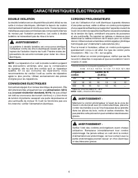
6 ELECTRICAL DOUBLE INSULATION Double insulation is a concept in safety in electric power tools, which eliminates the need for the usual three-wire grounded power cord. All exposed metal parts are isolated from the internal metal motor components with protecting insulation. Double insulated tools do...
Page 7 - GLOSSARY OF TERMS
7 GLOSSARY OF TERMS Push Blocks (for jointer planers) Device used to feed the workpiece over the jointer planer cutterhead during any operation. This aid helps keep the operator’s hands well away from the cutterhead. Push Blocks (for table saws) Device used to hold the workpiece during cutting opera...
Page 8 - FEATURES; PRODUCT SPECIFICATIONS
8 FEATURES Fig. 1 PRODUCT SPECIFICATIONS Arbor ......................................................................... 5/8 in.Blade Diameter ......................................................7-1/4 in.No Load Speed .................................... 5,800 r/min. (RPM)Input ......................
Page 10 - SELF-RETRACTING LOWER BLADE GUARD; TOOLS NEEDED
10 FEATURES SELF-RETRACTING LOWER BLADE GUARD The lower blade guard is made of shock-resistant, see-through plastic that provides protection from each side of the blade. It retracts over the upper blade guard as the saw is lowered into the workpiece. SPINDLE LOCK BUTTON The spindle lock button locks...
Page 11 - LOOSE PARTS LIST
11 LOOSE PARTS LIST Fig. 7 WARNING: The use of attachments or accessories not listed might be hazardous and could cause serious personal injury. The following items are included with your compound miter saw: WORK CLAMP DUST BAG BLADE WRENCH AAA BATTERIES REAR BRACKET/ CARRYING HANDLE MITER SAW Mit...
Page 12 - UNPACKING; ASSEMBLY; MOUNTING HOLES
12 UNPACKING This product requires assembly. Carefully lift miter saw from the carton by the “D” handle and the saw base, and place it on a level work surface. WARNING: Do not use this product if any parts on the Loose Parts List are already assembled to your product when you unpack it. Parts on t...
Page 13 - DUST BAG
13 31.6 22.5 22.5 31.6 ASSEMBLY INSTALLING THE REAR BRACKET/CARRYING HANDLE See Figure 9. CAUTION: A rear bracket is included with this miter saw to prevent tipping if the saw arm is released suddenly. Do not use this saw before installing the rear bracket/carrying handle and securely mounting the s...
Page 14 - INSTALLING BATTERIES FOR LASER; ALIGNING THE LASER GUIDE LINE
14 ASSEMBLY INSTALLING BATTERIES FOR LASER See Figure 12. Remove screw from battery compartment cover using the Phillips end of the supplied blade wrench. Remove cover and set aside. Install two AAA batteries according to polarity indicators inside the battery compartment. Replace the battery ...
Page 15 - TO INSTALL/REPLACE THE BLADE
15 ASSEMBLY TO INSTALL/REPLACE THE BLADE See Figures 14 - 15. WARNING: A 7-1/4 in. blade is the maximum blade capacity of the saw. Never use a blade that is too thick to allow outer blade washer to engage with the flats on the spindle. Larger blades will come in contact with the blade guards, while ...
Page 16 - SQUARING THE BLADE TO THE FENCE
16 WARNING: Make sure the spindle lock button is not engaged before reconnecting saw into power source. Never engage spindle lock button when blade is rotating. NOTE: Many of the illustrations in this manual show only portions of the compound miter saw. This is intentional so that we can clearly sho...
Page 18 - SQUARING THE BLADE TO THE MITER TABLE
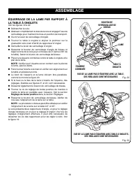
18 ASSEMBLY SQUARING THE BLADE TO THE MITER TABLE See Figures 19 - 23. Unplug the saw. Pull the saw arm all the way down and engage the lock pin to hold the saw arm in transport position. Unlock the miter lock lever. Rotate the miter table until the pointer aligns with zero detent on the mit...
Page 19 - OPERATION; APPLICATIONS; TO CROSS CUT
19 OPERATION WARNING: Do not allow familiarity with tools to make you careless. Remember that a careless fraction of a second is sufficient to inflict serious injury. WARNING: Always wear eye protection with side shields marked to comply with ANSI Z87.1. Failure to do so could result in objects bein...
Page 20 - TO BEVEL CUT
20 OPERATION Before turning on the saw, perform a dry run of the cutting operation just to make sure that no problems will occur when the cut is made. Grasp the saw handle firmly. Depress the switch lock with thumb then squeeze the switch trigger. Allow several seconds for the blade to reach max...
Page 21 - TO COMPOUND MITER CUT
21 OPERATION Grasp the saw handle firmly. Depress the switch lock with thumb then squeeze the switch trigger. Allow several seconds for the blade to reach maximum speed. Slowly lower the blade into and through the workpiece. Release the switch trigger and allow the saw blade to stop rotating b...
Page 22 - TO SUPPORT LONG WORKPIECES
22 0 OPERATION Place the workpiece flat on the miter table with one edge securely against the fence. If the board is warped, place the convex side against the fence. If the concave edge of a board is placed against the fence, the board could collapse on the blade at the end of the cut, jamming the...
Page 23 - CUTTING COMPOUND MITERS
23 OPERATION 4 PITCH OF SIDE NUMBER OF SIDES 0° 6 M- 45.00°B- 0.00° 5° 10° 15° 20° 25° 30° 35° 40° 45° 50° 55° 60° 65° 70° 75° 80° 85° 90° 5 7 8 9 10 M- 36.00°B- 0.00° M- 30.00°B- 0.00° M- 25.71°B- 0.00° M- 22.50°B- 0.00° M- 20.00°B- 0.00° M- 18.00°B- 0.00° Each B (Bevel) and M (Miter) Setting is Gi...
Page 24 - CUTTING CROWN MOLDING
24 OPERATION When setting the bevel and miter angles for compound miters, remember that the settings are interdependent; changing one angle changes the other angle as well.Keep in mind that the angles for crown molding are very precise and difficult to set. Since it is very easy for these angles to ...
Page 25 - CUTTING WARPED MATERIAL
25 OPERATION WARNING: To avoid a kickback and to avoid serious personal injury, never position the concave edge of bowed or warped material against the fence. Bevel Angle Type of Cut Setting Left side, inside corner 1. Top edge of molding against fence2. Miter table set right 31.62°3. Save left end ...
Page 26 - ADJUSTMENTS; PIVOT ADJUSTMENTS
26 ADJUSTMENTS WARNING: Before performing any adjustment, make sure the tool is unplugged from the power supply. Failure to heed this warning could result in serious personal injury. The compound miter saw has been adjusted at the factory for making very accurate cuts. However, some of the component...
Page 27 - TO ADJUST THE LASER GUIDE
27 ADJUSTMENTS DANGER: Laser radiation. Avoid direct eye contact with light source. WARNING: Use of controls or adjustments or performance of pro-cedures other than those specified herein can result in hazardous radiation exposure. TO ADJUST THE LASER GUIDE See Figure 34. Use the work clamp or a C...
Page 28 - MAINTENANCE; GENERAL MAINTENANCE; This product has a Three-year Limited Warranty.
28 MAINTENANCE WARNING: When servicing, use only identical replacement parts. Use of any other parts can create a hazard or cause product damage. WARNING: Always wear eye protection with side shields marked to comply with ANSI Z87.1. Failure to do so could result in objects being thrown into your ey...
Page 29 - RÈGLES DE SÉCURITÉ GÉNÉRALES; LIRE TOUTES LES INSTRUCTIONS
2 RÈGLES DE SÉCURITÉ GÉNÉRALES AVERTISSEMENT : Lire et veiller à bien comprendre toutes les instructions. Le non respect de toutes les instructions ci-dessous peut entraîner un choc électrique, un incendie et / ou des blessures graves. LIRE TOUTES LES INSTRUCTIONS VEILLER À BIEN CONNAÎTRE L’OUTIL....
Page 31 - RÈGLES DE SÉCURITÉ PARTICULIÈRES
4 RÈGLES DE SÉCURITÉ PARTICULIÈRES S’ASSURER QUE LA LAME NE TOUCHE PAS LA PIÈCE. Ne jamais mettre la scie en marche si la lame touche la pièce à couper. Toujours laisser le moteur atteindre sa pleine vitesse de rotation avant de commencer la coupe. S’ASSURER QUE LA TABLE À ONGLETS ET LE BRAS DE ...
Page 32 - SYMBOLES
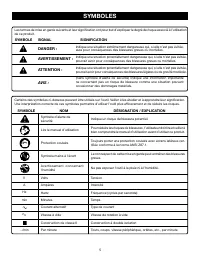
5 SYMBOLES Certains des symboles ci-dessous peuvent être utilisés sur l’outil. Veiller à les étudier et à apprendre leur signification. Une interprétation correcte de ces symboles permettra d’utiliser l’outil plus efficacement et de réduire les risques. SYMBOLE NOM DÉSIGNATION / EXPLICATION Symbole ...
Page 33 - CORDONS PROLONGATEURS; CARACTÉRISTIQUES ÉLECTRIQUES; DOUBLE ISOLATION; CONNEXIONS ÉLECTRIQUES
6 CORDONS PROLONGATEURS Lors de l’utilisation d’un outil électrique à grande distance d’une prise secteur, veiller à utiliser un cordon prolongateur d’une capacité suffisante pour supporter l’appel de courant de l’outil. Un cordon de capacité insuffisante causerait une baisse de la tension de ligne,...
Page 34 - GLOSSAIRE
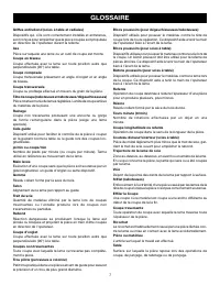
7 GLOSSAIRE Blocs poussoirs (pour dégauchisseuses/raboteuses) Dispositif utilisés pour pousser le matériau contre la tête de coupe lors de toute opération. Ce dispositif aide à tenir la main de l’opérateur bien à l’écart de la lame. Blocs poussoirs (pour scies à table) Dispositifs utilisés pour pous...
Page 35 - CARACTÉRISTIQUES; FICHE TECHNIQUE
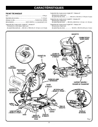
8 CARACTÉRISTIQUES Fig. 1 FICHE TECHNIQUE Axe ..................................................................................... 5/8 poDiamètre de la lame.........................................................7-1/4 poVitesse à vide .................................................. 5 800 r/min ...
Page 37 - BOUTON DE VERROUILLAGE DE BROCHE; OUTILS NÉCESSAIRES
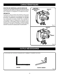
10 CARACTÉRISTIQUES BOUTON DE VERROUILLAGE DE BROCHE Le bouton de verrouillage de broche verrouille la broche en empéchant la lame de tourner. Maintenir le bouton enfoncé pour l’installation, le changement ou la dépose de la lame. GÂCHETTE La scie ne se met en marche que lorsque le verrou de la comm...
Page 38 - LISTE DES PIÈCES DÉTACHÉES
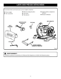
11 LISTE DES PIÈCES DÉTACHÉES AVERTISSEMENT : L’utilisation de pièces et accessoires non listés peut être dangereux et entraîner des blessures graves. SCIE À ONGLETS SAC À POUSSIÈRE CLÉ À LAME PILES AAA SUPPORT ARRIÈRE / POIGNÉE DE TRANSPORT Fig. 6 BASE DE LA SCIE À ONGLETS Les articles suivant sont...
Page 39 - ASSEMBLAGE; TROUS DE FIXATION
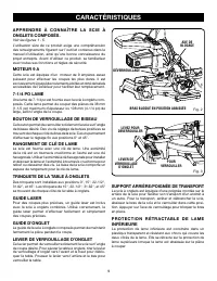
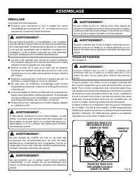
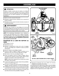
12 ASSEMBLAGE AVERTISSEMENT : Ne pas mettre la scie en marche sans s’être assuré de l’absence d’interférence entre la lame et le guide d’onglets. La lame pourrait être endommagée si elle entrait en contact avec le guide d’onglets pendant le fonctionnement. AVERTISSEMENT : Toujours s’assurer que la s...
Page 40 - SAC À POUSSIÈRE
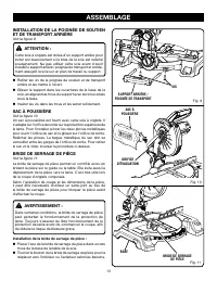
13 INSTALLATION DE LA POIGNÉE DE SOUTIEN ET DE TRANSPORT ARRIÈRE Voir la figure 9. ATTENTION : Cette scie à onglets est dotée d’un support arrière pour éviter son basculement si le bras de la scie est relâché soudainement. Ne pas utiliser cette scie avant d’avoir installé le support arrière / poign...
Page 41 - INSTALLATION DES PILES DANS LE LASER; ALIGNEMENT DU TRAIT LASER
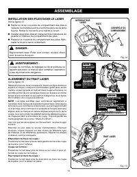
14 INSTALLATION DES PILES DANS LE LASER Voir la figure 12. Retirer la vis du couvercle du compartiment des piles à l’aide de l’extrémité à pointe cruciforme de la clé de lame fournie. Retirer le couvercle et le mettre à l’écart. Installer deux piles AAA en respectant les indicateurs de polarité ...
Page 42 - INSTALLATION / REMPLACEMENT DE LA LAME
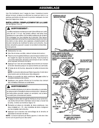
15 31.6 22.5 22.5 31.6 Une fois familiarisé avec l’usage du laser, l’opérateur pourra effacer le tracé, le laisser ou effectuer la coupe sur celui-ci. La pratique permettra de découvrir la position adéquate du trait laser par rapport au tracé. INSTALLATION / REMPLACEMENT DE LA LAME Voir les figures ...
Page 46 - UTILISATION; COUPE TRANSVERSALE
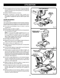
19 UTILISATION AVERTISSEMENT : Ne pas laisser la familiarité avec l’outil faire oublier la prudence. Ne pas oublier qu’une fraction de seconde d’inattention peut entraîner des blessures graves. AVERTISSEMENT : Toujours porter une protection oculaire avec écrans latéraux certifiée conforme à la norme...
Page 47 - COUPE EN BISEAU
20 UTILISATION Saisir la poignée de la scie fermement. Enfoncer le dispositif de verrouillage avec le po puis serrer la gâchette.Attendre quelques secondes que la lame parvienne à sa vitesse de rotation maximum. Abaisser lentement la lame sur la pièce. Relâcher la gâchette et attendre l’arrêt ...
Page 49 - SUPPORT DE PIÈCES LONGUES
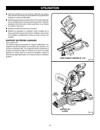
22 0 UTILISATION Avant de mettre la scie en marche, effectuer un essai à vide, afin de s’assurer qu’aucun problème ne se présentera lorsque la coupe est effectuée. Saisir la poignée de la scie fermement. Enfoncer le dispositif de verrouillage avec le po puis serrer la gâchette. Attendre quelques...
Page 50 - COUPE D’ONGLETS COMPOSÉS
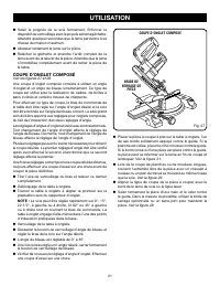
23 UTILISATION 4 ANGLE DE CÔTÉ NOMBRE DE CÔTÉS 0° 6 5° 10° 15° 20° 25° 30° 35° 40° 45° 50° 55° 60° 65° 70° 75° 80° 85° 90° 5 7 8 9 10 Chaque angle B (biseau) et O (onglet) est indiquée au 0,005ème de degré le plus proche. RÉGLAGES D’ANGLES COMPOSÉS POUR LES CONSTRUCTIONS COURANTES COUPE D’ONGLETS CO...
Page 51 - COUPE DE MOULURE COURONNÉE
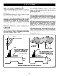
24 UTILISATION Lors du réglage des angles de biseau et d’onglet pour une coupe composée, ne pas oublier que les réglages des deux angles sont relationnels, la modification de l’un entraîne la modification de l’autre.Se rappeler également que les angles de moulure couronnée doivent être extrêmement p...
Page 52 - COUPE DE PIÈCES VOILÉES
25 UTILISATION Réglage de l’angle de Type de coupe biseau Coin intérieur, côté gauche 1. Bord supérieur de la moulure contre le guide2. Angle d’onglet réglé à droite sur 31,62° 3. Conserver la section gauche de la pièce coupée. Coin intérieur, côté droit 1. Bord inférieur de la moulure contre le gui...
Page 53 - RÉGLAGES; RÉGLAGES DES PIVOTS
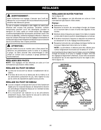
26 RÉGLAGES AVERTISSEMENT : Avant d’effectuer tout réglage, s’assurer que l’outil est débranché. Le non respect de cet avertissement pourrait entraîner des blessures graves. La scie à onglets composés a été réglée en usine pour effectuer des coupes très précises. Toutefois, certains composants peuve...
Page 54 - RÉGLAGE DU LASER
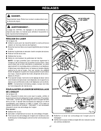
27 RÉGLAGES DANGER : Rayonnement laser. Éviter tout contact oculaire direct avec la source du rayon. AVERTISSEMENT : L’usage de contrôles, de réglages ou de procédures ne figurant pas dans ce manuel peut entraîner l’exposition à des rayonnements dangereux. RÉGLAGE DU LASER Voir la figure 34. Uti...
Page 55 - ENTRETIEN; ENTRETIEN GÉNÉRAL; Ce produit possède une garantie limitée de trois ans.
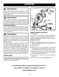
28 ENTRETIEN AVERTISSEMENT : Utiliser exclusivement des pièces identiques à celles d’origine pour les réparations. L’usage de toute autre pièce pourrait créer une situation dangereuse ou endommager l’outil. AVERTISSEMENT : Toujours porter une protection oculaire avec écrans latéraux certifiée confor...
Page 56 - REGLAS DE SEGURIDAD GENERALES; LEA TODAS LAS INSTRUCCIONES
2 REGLAS DE SEGURIDAD GENERALES ADVERTENCIA: L e a y c o m p r e n d a t o d a s l a s i n s t r u c c i o n e s . E l incumplimiento de las instrucciones señaladas abajo puede causar descargas eléctricas, incendios y lesiones serias. LEA TODAS LAS INSTRUCCIONES FAMILIARÍCESE CON SU HERRAMIENTA EL...
Page 58 - REGLAS DE SEGURIDAD ESPECÍFICAS
4 REGLAS DE SEGURIDAD ESPECÍFICAS ASEGÚRESE DE QUE LA HOJA TRASPASE LA PIEZA DE TRABAJO. Nunca arranque la sierra con la hoja tocando la pieza de trabajo. Permita que el motor se detenga comple-tamente antes de iniciar el corte. ASEGÚRESE DE QUE LA MESA DE INGLETES Y EL BRAZO DE LA SIERRA (FUNCI...
Page 59 - SÍMBOLOS; SÍMBOLO
5 SÍMBOLOS Las siguientes palabras de señalización y sus significados tienen el objeto de explicar los niveles de riesgo relacionados con este producto. SÍMBOLO SEÑAL SIGNIFICADO PELIGRO: Indicates an imminently hazardous situation, which, if not avoided, will result in death or serious injury. ADVE...
Page 60 - ASPECTOS ELÉCTRICOS; DOBLE AISLAMIENTO; CONEXIÓN ELÉCTRICA; CORDONES DE EXTENSIÓN
6 ASPECTOS ELÉCTRICOS DOBLE AISLAMIENTO El doble aislamiento es una característica de seguridad de las herramientas eléctricas, la cual elimina la necesidad de usar el típico cordón eléctrico de tres conductores con conexión a tierra. Todas las partes metálicas expuestas están aisladas de los compon...
Page 61 - GLOSARIO DE TÉRMINOS
7 GLOSARIO DE TÉRMINOS Bloques empujadores (para cepillos de juntas) Son dispositivos empleados para avanzar la pieza de trabajo por el cepillo de juntas durante cualquier operación. Este medio ayuda al operador a mantener las manos alejadas de la cabeza de corte. Bloques empujadores (para sierras d...
Page 62 - CARACTERÍSTICAS; ESPECIFICACIONES DEL PRODUCTO
8 CARACTERÍSTICAS ESPECIFICACIONES DEL PRODUCTO Árbol ............................................................................... 5/8 pulg. Diámetro de la hoja .....................................................7-1/4 pulg.Velocidad en vacío .......................................... 5 800 r/mi...
Page 63 - ERRA INGLETEADORA COMBINADA; PERILLA DE FIJACIÓN DE BISEL
9 CARACTERÍSTICAS FAMILÍCESE CON LA SI- ERRA INGLETEADORA COMBINADA Vea las figuras 1 a 5. El uso seguro que este producto requiere la comprensión de la información impresa en la herramienta y en el manual del operador así como ciertos conocimientos sobre el proyecto a realizar. Antes de usar este p...
Page 64 - PROTECCIÓN INFERIOR AUTORRETRAÍBLE; HERRAMIENTAS NECESARIAS
10 CARACTERÍSTICAS PROTECCIÓN INFERIOR AUTORRETRAÍBLE DE LA HOJA La protección inferior de la hoja está hecha de plastico transparente resistente a impactos que proporciona pro-tección a cada lado de la hoja. Se retrae por encima de la protección superior a medida que se baja la hoja hacia la pieza ...
Page 65 - LISTA DE PIEZAS SUELTAS
11 LISTA DE PIEZAS SUELTAS ADVERTENCIA: El empleo de aditamentos o accesorios no enumerados arriba podría ser peligros y causar lesiones serias. SACO CAPTAPOLVO LLAVE DE HOJA BATERÍAS AAA SOPORTE TRASERO/ MANGO DE ACARREO Fig. 7 Vienen incluidos los siguientes artículos con la sierra ingleteadora co...
Page 66 - AGUJEROS DE MONTAJE; ARMADO; DESEMPAQUETADO
12 ADVERTENCIA: No encienda la sierra ingleteadora combinada sin revisar para ver si hay interferencia entre la hoja y la guía de ingletes. Puede dañarse la hoja si toca la guía de ingletes durante el funcionamiento de la sierra. ADVERTENCIA: Siempre asegúrese de que la sierra ingleteadora combinada...
Page 67 - SACO CAPTAPOLVO
13 ARMADO INSTALACIÓN DEL SOPORTE TRASERO Y DEL MANGO DE ACARREO Vea la figura 9. ADVERTENCIA: Con esta sierra ingleteadora se incluye un soporte trasero para evitar un volcamiento si se suelta súbitamente el brazo de la sierra. No use esta sierra sin haber instalado el soporte trasero/mango de acar...
Page 68 - ALINEACIÓN DE LA LÍNEA DE LA GUÍA LÁSER
14 ARMADO Lock trigger prior to adjusting laser. AVOID EXPOSURE: Laser radiation emitted from this aperture. Fixer gâchette avant laser est réglagé. EVITER L’EXPOSITION : Rayonnement laser émise de cet orifice. Asegure gatillo antes de ajuste de laser. EVITE LA EXPOSIOCIÔN: Radiactiôn laser se emite...
Page 69 - PARA INSTALAR O REEMPLAZAR LA HOJA
15 PARA INSTALAR O REEMPLAZAR LA HOJA Vea las figuras 14 y 15. ADVERTENCIA: La sierra tiene capacidad para hojas hasta de un diámetro de 7-1/4 pulg. Nunca utilice una hoja tan gruesa que la arandela exterior de la hoja no se enganche en las partes planas del husillo. Las hojas más grandes tocan las ...
Page 70 - ESCUADRADO DE LA HOJA CON LA GUÍA
16 ARMADO Apriete firmemente el perno de la hoja. Vuelva a colocar la protección inferior y la tapa del perno de la hoja. Vuelva a colocar el tornillo de la cubierta del perno de la segueta y apriételo firmemente. ADVERTENCIA: S’assurer que le bouton de verrouillage de la broche n’est pas enga...
Page 73 - FUNCIONAMIENTO; APLICACIONES
19 FUNCIONAMIENTO ADVERTENCIA: No permita que su familarización con las herramientas lo vuelva descuidado. Tenga presente que un descuido de un instante es suficiente para causar una lesión grave. ADVERTENCIA: Siempre póngase protección ocular con la marca de cumplimiento de la norma ANSI Z87.1. Si ...
Page 74 - PARA CORTAR A BISEL
20 FUNCIONAMIENTO Sujete firmemente el mango de la sierra. Oprima el seguro del interruptor con el pulgar y luego oprima el gatillo. Permita transcurrir varios segundos para que la hoja alcance su velocidad máxima. Baje lentamente la hoja de la sierra hacia la pieza de trabajo y corte ésta. Su...
Page 75 - PARA EFECTUAR UN CORTE A INGLETE
21 FUNCIONAMIENTO Una vez puesto el brazo de la sierra en el ángulo deseado, apriete firmemente la perilla de fijación de bisel. Vuelva a revisar el ajuste del ángulo de inglete. Efectúe un corte de prueba en material de desecho. Coloque la pieza de trabajo horizontal en la mesa de ingletes, c...
Page 76 - PARA APOYAR LAS PIEZAS DE TRABAJO
22 0 FUNCIONAMIENTO CORTE A INGLETE COMBINADO DE 45° X 45° PIEZA DE TRABAJO LARGA SOPORTES DE LA PIEZA DE TRABAJO Fig. 29 Fig. 28 Sujete firmemente el mango de la sierra. Oprima el seguro del interruptor con el pulgar y luego oprima el gatillo. Permita transcurrir varios segundos para que la hoja ...
Page 77 - CÓMO EFECTUAR CORTES A INGLETE COMBINADOS
23 FUNCIONAMIENTO Cada cantidad, B (bisel) y M (inglete), se da con una tolerancia de 0,005°. AJUSTES DE ÁNGULOS COMBINADOS PARA ESTRUCTURAS COMUNES CÓMO EFECTUAR CORTES A INGLETE COMBINADOS Como ayuda para realizar los ajustes correctos, se suministra la siguiente tabla de ángulos combinados. Puest...
Page 78 - CÓMO CORTAR MOLDURAS DE CORONA
24 FUNCIONAMIENTO Al fijar los ángulos de bisel e inglete de los cortes a inglete combinados, recuerde que los ajustes son interdependientes; si se cambia un ángulo se cambia el otro también.Tenga presente que los ángulos de las molduras de corona son muy precisos y difíciles de ajustar. Puesto que ...
Page 79 - CÓMO CORTAR MATERIAL DISTORSIONADO
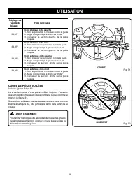
25 FUNCIONAMIENTO ADVERTENCIA: Para evitar un contragolpe y posibles lesiones graves, nunca coloque el canto cóncavo de un material arqueado o distorsionado contra la guía. Ajuste del ángulo de bisel Tipo de corte Lado izquierdo, esquina interior 1. Canto superior moldura contra guía2. Mesa ingletes...
Page 80 - AJUSTES; AJUSTES DE LOS PIVOTES
26 AJUSTES ADVERTENCIA: Antes de efectuar cualquier ajuste, asegúrese de que la herramienta esté desconectada del suministro de corri-ente. La inobservancia de esta advertencia podría causar lesiones corporales serias. La sierra ingleteadora combinada ha sido ajustada en la fábri-ca para producir co...
Page 81 - PARA AJUSTAR LA GUÍA LASER
27 AJUSTES PELIGRO: Radiación láser. Evite todo contacto directo de los ojos con la fuente de luz. ADVERTENCIA: Todo control, ajuste o procedimiento diferente de los es-pecificados aquí, puede causar una exposición peligrosa a la radiación. PARA AJUSTAR LA GUÍA LASER Vea la figura 34. Use la pre...
Page 82 - MANTENIMIENTO; MANTENIMIENTO GENERAL; Este producto cuenta con una garantía limitada de tres años.
28 MANTENIMIENTO ADVERTENCIA: Al dar servicio a la unidad, sólo utilice piezas de repuesto idénticas. El empleo de piezas diferentes puede causar un peligro o dañar el producto. ADVERTENCIA: Cuando utilice este producto, siempre póngase protección ocular con protección lateral con la marca de cumpli...
Page 83 - CALIFORNIA PROPOSITION 65; Wash hands after handling.; PROPOSITION 65 DE L’ÉTAT DE CALIFORNIE; Bien se laver les mains après toute manipulation.
CALIFORNIA - PROPUESTA DE LEY NÚM. 65 ADVERTENCIA: Este producto y algunos polvos generados al efectuarse operaciones de lijado, aserrado, esmerilado, taladrado y otras actividades de la construcción, contienen sustancias químicas reconocidas por el estado de California como causantes de cáncer, def...
Page 84 - OPERATOR’S MANUAL; MANUEL D’UTILISATION / MANUAL DEL OPERADOR
9900009553-27-14 (REV:01) ONE WORLD TECHNOLOGIES, INC. 1428 Pearman Dairy Road, Anderson, SC 29625 • Phone 1-800-525-2579 États-Unis, Téléphone 1-800-525-2579 • USA, Teléfono 1-800-525-2579 www.ryobitools.com A subsidiary of Techtronic Industries Co., LTD OTC: TTNDY RYOBI is a registered trademark o...


 Ryobi P553
User Manual
Ryobi P553
User Manual
 Ryobi P553-PSK005
User Manual
Ryobi P553-PSK005
User Manual
 Ryobi P553-PSK006
User Manual
Ryobi P553-PSK006
User Manual
 Ryobi PBLMS01B
User Manual
Ryobi PBLMS01B
User Manual
 Ryobi PBLMS01K
User Manual
Ryobi PBLMS01K
User Manual
 Ryobi PBLMS01K-A18MS01G
User Manual
Ryobi PBLMS01K-A18MS01G
User Manual
 Ryobi PBLMS01K-PBP004
User Manual
Ryobi PBLMS01K-PBP004
User Manual
 Ryobi PBT01B
User Manual
Ryobi PBT01B
User Manual
 Ryobi PBT01B-A067101
User Manual
Ryobi PBT01B-A067101
User Manual
 Ryobi PBT01B-A18MS01G
User Manual
Ryobi PBT01B-A18MS01G
User Manual
 Ryobi PBT01B-PBP004
User Manual
Ryobi PBT01B-PBP004
User Manual
 Ryobi PBT01B-PCL204HPK
User Manual
Ryobi PBT01B-PCL204HPK
User Manual
 Ryobi PBT01B-PSK005
User Manual
Ryobi PBT01B-PSK005
User Manual
 Ryobi TS1144
User Manual
Ryobi TS1144
User Manual
 Ryobi TS1346
User Manual
Ryobi TS1346
User Manual
 Ryobi TSS103
User Manual
Ryobi TSS103
User Manual
 Ryobi TSS103-A181001
User Manual
Ryobi TSS103-A181001
User Manual
 Ryobi TSS103-A181002
User Manual
Ryobi TSS103-A181002
User Manual
 Ryobi TSS103-A18MS01G
User Manual
Ryobi TSS103-A18MS01G
User Manual
 Ryobi TSS103-RMS10G
User Manual
Ryobi TSS103-RMS10G
User Manual